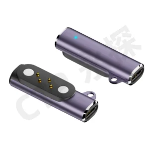
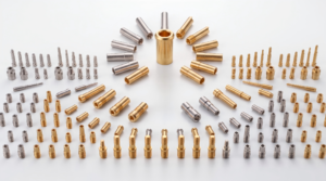
Magnetic pogo pin connectors can support modular AR/VR headset
architectures by providing removable electrical interfaces for charging,
external batteries, sensors and project-specific accessories. Magnets can
assist capture and retention while spring-loaded contacts provide the
conductive paths. However, magnetic attachment alone does not establish
high-speed data capability, hot-swap operation, EMI immunity or
environmental sealing. Successful integration requires a defined Pin Map,
controlled working stroke, mechanical alignment, breakaway behavior,
power sequencing and complete electrical validation.
Why AR/VR Headsets Create a Different Connector Problem
Head-mounted electronics combine several design constraints that are less
important in many conventional devices.
The interface may need to remain compact while the product is repeatedly
moved, worn close to the skin and connected to removable accessories.Possible removable modules include:
- external battery packs;
- charging cables;
- sensor accessories;
- tracking modules;
- audio accessories;
- service or diagnostic interfaces;
- project-specific expansion modules.
For these applications, connector selection affects more than electrical
continuity. It also influences user comfort, cable loading, accessory
replacement, mechanical package size and serviceability.
Magnetic Pogo Pin Interfaces Separate Capture from Electrical Contact
A magnetic pogo pin connector combines two different functions.

Magnets provide mechanical capture and retention.

Pogo pins and mating targets provide electrical conduction.

Keeping these functions separate is important because stronger magnets do
not automatically improve electrical performance, and lower contact
resistance does not determine magnetic retention.| Interface Function | Primary Design Element |
|---|---|
| Initial Capture | Magnet arrangement |
| Orientation | Housing geometry or mechanical coding |
| Final Position | Mechanical datums and mating surfaces |
| Electrical Contact | Pogo pins and mating targets |
| Working Compression | Mechanical stop and tolerance stack |
| Retention / Release | Magnetic structure and product geometry |
Headset Ergonomics Should Influence the Connector Architecture
AR/VR devices are worn on the user's head, so the location and behavior of
cables and accessory modules can influence the mechanical experience of the
complete product.
Connector design may need to consider:
- connector mass;
- cable weight;
- cable pull direction;
- location relative to the headset center of mass;
- user head movement;
- accessory removal direction;
- retention force;
- desired breakaway behavior.
A connector that is electrically suitable can still create an undesirable
user experience if the cable or accessory produces excessive mechanical
load on the headset.
Breakaway Behavior Can Be Useful for Head-Mounted Devices
A magnetic interface can be designed to release when a cable is pulled in
a defined direction.

This may reduce how much cable force is transferred into the headset, but
the result depends on the complete mechanical design.
Breakaway behavior can be affected by:
- magnet position;
- seated retention;
- connector shape;
- cable angle;
- axial versus peel loading;
- headset mass;
- surface friction.
A magnetic connector should therefore not simply be described as
“breakaway” without defining the intended separation direction.
Capture Force, Retention and Separation Are Different Requirements
One generic magnetic-force value cannot describe the complete behavior of
an AR/VR accessory interface.| Magnetic Behavior | Engineering Meaning |
|---|---|
| Capture | Attraction during connector approach |
| Seated Retention | Force holding the fully connected accessory in place |
| Axial Separation | Force required for straight pull-off |
| Peel Separation | Behavior when separation begins from one edge |
| Off-Axis Load | Behavior during twisting or lateral disturbance |
Stronger Magnets Are Not Automatically Better
Increasing magnetic retention may help prevent unintended separation, but
excessive magnetic force can also create trade-offs.
These can include:
- higher user removal force;
- larger housing loads;
- more lateral sliding during final capture;
- reduced breakaway behavior;
- greater attraction of ferromagnetic debris.
Magnetic performance should therefore be selected around the actual
accessory mass and user interaction.
Working Stroke Must Be Controlled After Final Seating
In a pogo pin interface, the spring-loaded contact should remain inside its
approved working-compression range after the accessory reaches its final
seated position.
A simplified relationship is:
S = Hfree - Hseatedwhere:
- S is actual pogo pin compression;
- Hfree is the installed free contact height;
- Hseated is the final mating height.
The complete tolerance stack can include:
- pogo pin free-height variation;
- target height and flatness;
- headset housing tolerance;
- accessory housing tolerance;
- PCB position;
- mechanical-stop position.
| Stroke Condition | Possible Effect |
|---|---|
| Insufficient Compression | Intermittent or unstable electrical contact |
| Approved Working Stroke | Intended contact-force and electrical state |
| Excessive Compression | Spring bottoming, target wear or unnecessary structural load |
| Unequal Compression | Different electrical conditions across the contact array |
Magnetic Force Should Not Define Working Stroke
The magnets can pull the two halves together, but the final mating position
should normally be established by the mechanical structure.

Otherwise, variations in magnetic force, assembly geometry or foreign
debris may change pogo pin compression.

Mechanical stops and defined datum surfaces provide a more controllable way
to establish the final electrical contact condition.
Build the Pin Map Around the Accessory Function
An AR/VR magnetic connector should not be selected only by pin count.Possible contact functions include:
- power;
- power return;
- accessory detection;
- accessory identification;
- enable control;
- project-specific control signals;
- project-specific data signals;
- service or diagnostic contacts.
The number and location of contacts should follow the Pin Map and electrical
requirements of the actual accessory.
Example AR/VR Accessory Interfaces
| Accessory | Possible Electrical Functions | Primary Engineering Focus |
|---|---|---|
| External Battery | Power, return, detection and identification | Current path, retention and removal sequence |
| Charging Cable | Power, return and project-specific detection | Breakaway behavior and thermal performance |
| Sensor Module | Power, identification and project-specific signals | Pin Map and complete signal path |
| Tracking Accessory | Power and project-specific communication | Mechanical positioning and channel validation |
| Service Fixture | Power, programming or diagnostic functions | Repeatability and controlled access |
These examples illustrate possible architectures rather than universal
contact assignments.
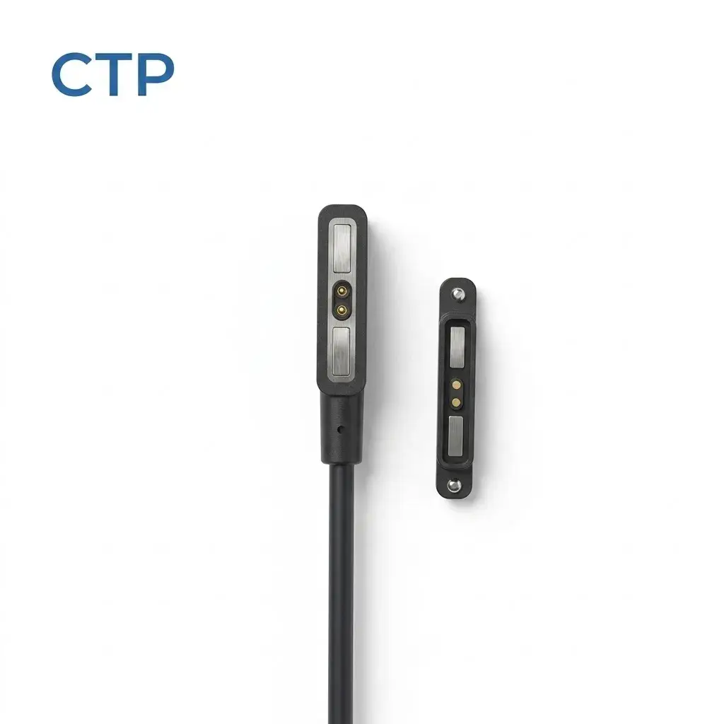
A Two-Pin Magnetic Connector Is Primarily a Power Interface
A two-contact magnetic cable can provide two conductive paths, commonly
suitable for a project-specific power and return architecture.

Two visible contacts alone do not establish a high-speed data connection.

If an AR/VR accessory requires data in addition to power, the connector
architecture must provide the required independent electrical paths and the
complete signal channel must be validated.
Pin Count Does Not Prove 10Gbps Capability
High-speed digital performance cannot be determined from pogo pin count
alone.
Signal integrity can depend on:
- contact layout;
- signal and return allocation;
- differential geometry where applicable;
- contact spacing;
- PCB transitions;
- cable construction;
- crosstalk;
- insertion loss;
- return loss;
- complete-channel length;
- the electrical requirements of the intended protocol.
A specific data rate should therefore be stated only after the complete
connector and channel architecture has been designed and validated for that
requirement.
Magnetic Pogo Pins Do Not Eliminate Rendering Latency
User-perceived AR/VR latency depends on the complete sensing, processing,
rendering, display and software pipeline.

The connector is only one electrical transition inside that system.

A properly designed connector should preserve the required electrical
channel characteristics, but it should not be marketed as independently
eliminating motion-to-photon or rendering latency.
Power and Data Should Be Treated as Separate Engineering Problems
A connector may need to carry both electrical power and signal channels,
but their design priorities are different.| Electrical Function | Primary Engineering Concerns |
|---|---|
| Power | Current, voltage drop, contact resistance and temperature rise |
| Detection / ID | Logic state during mating and removal |
| Low-Speed Control | Reference path and electrical compatibility |
| High-Speed Data | Complete-channel signal integrity and return-path architecture |
High-Current Capability Requires Complete-Path Testing
Charging capability is not defined by the pogo pin alone.A simplified power path may include:
    Power Source
    →
    Cable / PCB
    →
    Connector Termination
    →
    Pogo Pin
    →
    Contact Interface
    →
    Mating Target
    →
    Headset PCB
    →
    Charging / Power Electronics
The complete path resistance can be represented as:
    Rpath =
    Rsource +
    Rtermination +
    Rpogo +
    Rinterface +
    Rtarget +
    Rdevice
The voltage drop is:
Vdrop = I × RpathThe resistive loss is:
Ploss = I² × Rpath

Current capability should therefore be confirmed through complete-path
voltage-drop and temperature-rise testing.
External Battery Modules Are Not Automatically Hot-Swappable
A removable magnetic battery interface does not automatically mean that the
battery can be disconnected while the headset continues operating.
True hot-swap behavior may require:
- multiple power sources;
- hold-up energy;
- power-path switching;
- battery detection;
- controlled sequencing;
- firmware state management;
- fault protection.
The magnetic connector only provides the physical electrical interface.Partial Mating Should Be Treated as a Real Electrical State
The magnets can begin attracting before every pogo pin is fully seated.| Mating Condition | Possible Effect | Design Review |
|---|---|---|
| One Contact Engages First | Unexpected electrical sequence | Pin Map and power logic |
| Connector Is Tilted | Unequal pogo pin compression | Mechanical alignment |
| Accessory Detected Before Full Seating | System may respond too early | Validation logic |
| Debris Prevents Full Seating | Unstable electrical contact | Contamination strategy |
| Accessory Separates Under Load | Electrical transient or arcing | Power-disable sequence |
Sweat Exposure Is Different from Waterproof Certification
AR/VR headsets can operate close to the user's face and head, so connector
areas may be exposed to perspiration depending on product geometry and use.

Sweat exposure can affect:- exposed contact surfaces;
- mating targets;
- metal housings;
- adhesives;
- sealing structures;
- connector-to-enclosure joints.
The project should therefore define the expected exposure and appropriate
material and environmental validation.

A connector should not automatically be described as IP68 or
sweat-proof without a defined and tested assembly.
A Flush Interface Does Not Automatically Make the Headset Waterproof
Replacing a deep receptacle with a flush contact surface may simplify some
enclosure structures, but the complete ingress-protection boundary still
needs to be engineered.
The sealing system may include:
- pogo pin feedthroughs;
- connector housing;
- insert molding or potting where applicable;
- gaskets;
- housing joints;
- PCB termination;
- other openings in the headset enclosure.
Mated and Unmated States Need Separate Environmental Review
| Interface State | Engineering Question |
|---|---|
| Fully Mated | Are contacts and feedthroughs protected as intended? |
| Partially Mated | Can moisture reach adjacent or energized contacts? |
| Unmated | Are exposed contacts protected from normal user exposure? |
| After Sweat / Moisture Exposure | Is cleaning or drying required before reconnection? |
Magnets Can Attract Metallic Debris
Permanent magnets near the electrical interface can attract ferromagnetic
particles.
Foreign particles may:
- prevent complete seating;
- change pogo pin compression;
- scratch mating targets;
- bridge adjacent contact regions;
- increase local electrical resistance.
Contact spacing, housing geometry, cleaning access and electrical
protection should therefore be evaluated in the complete product.
A Metal Housing Is Not Automatically an EMI Shield
A conductive housing can contribute to a shielding architecture, but
effective EMI control requires more than surrounding the connector with
metal.
Performance can depend on:
- housing continuity;
- shield termination;
- chassis connection;
- apertures and gaps;
- signal return paths;
- PCB layout;
- cable shielding;
- frequency range.
EMI and signal-integrity performance should therefore be validated using
the complete headset and accessory electrical architecture.
Connector Placement Should Consider RF and Sensor Architecture
AR/VR headsets can integrate antennas, inertial sensors, cameras and other
electronics inside a compact enclosure.

The connector location, magnet structure and current paths should therefore
be reviewed together with the product's RF, sensing and PCB architecture.

This does not mean that magnets or pogo pins automatically interfere with
these systems. It means the interaction should be evaluated as part of the
complete product design rather than assumed to be harmless or harmful.
Lifecycle Testing Should Reproduce Headset Use
A generic mating-cycle number is not sufficient to establish AR/VR
connector service life.
A useful test record should define:
- connector revision;
- working stroke;
- mating target;
- approach angle;
- mating and removal speed;
- electrical load;
- cable pull conditions;
- sweat or moisture exposure where applicable;
- contamination conditions;
- acceptance criteria.
A cycle count measured under a clean and unloaded laboratory condition
should not automatically be applied to a head-mounted device used under
dynamic movement.
Example AR/VR Magnetic Connector Selection Parameters
| Parameter | Engineering Definition |
|---|---|
| Accessory Type | Battery, charging cable, sensor, dock or service module |
| Pin Count | Number of independent electrical paths required |
| Pin Map | Power, return, detection, control and signal allocation |
| Working Stroke | Minimum, nominal and maximum pogo pin compression |
| Contact Force | Specify at the intended working stroke |
| Mating Target | Define dimensions, finish, flatness and support |
| Capture Behavior | Magnetic attraction during approach |
| Seated Retention | Holding force in the fully seated state |
| Breakaway Behavior | Separation force in intended pull directions |
| Continuous Current | Confirm through complete-path electrical and thermal testing |
| Signal Requirement | Define the actual protocol and complete-channel requirements |
| Environment | Sweat, moisture, skin oil, dust and cleaning exposure |
| Lifecycle | Define using realistic mating and electrical conditions |
Recommended Validation Matrix
| Validation Area | Recommended Evaluation |
|---|---|
| Working Stroke | Verify minimum, nominal and maximum compression |
| Magnetic Capture | Evaluate representative approach positions |
| Retention | Measure seated and project-specific off-axis loads |
| Breakaway | Evaluate intended cable and accessory pull directions |
| Partial Mating | Test tilted, offset and incompletely seated conditions |
| Power Path | Measure complete-path voltage drop and temperature rise |
| Signal Path | Validate the complete channel for the intended interface |
| Sweat / Moisture | Evaluate representative exposure and recovery conditions |
| Metallic Debris | Evaluate attraction, seating and contact-bridging risk |
| Repeated Mating | Monitor resistance, wear, working stroke and magnetic behavior |
| Removal Under Load | Verify power-disable behavior before physical separation |
Information Required for Engineering Review
| Project Input | Information to Provide |
|---|---|
| Headset / Accessory Type | AR headset, VR headset, battery, cable, sensor or other module |
| Pin Map | Function of every electrical contact |
| Electrical Conditions | Voltage, continuous current and peak current |
| Signal Requirement | Protocol, data rate and complete-channel requirements where applicable |
| Available Space | Maximum connector length, width and height |
| Working Stroke | Minimum, nominal and maximum pogo pin compression |
| Mating Direction | Approach and final seating direction |
| Breakaway Requirement | Desired cable or accessory separation behavior |
| Retention Requirement | Accessory mass and expected dynamic loading |
| Environment | Sweat, moisture, dust, skin oil and cleaning exposure |
| Lifecycle Target | Required mating cycles and acceptance criteria |
| Project Files | 2D drawing, 3D model, PCB layout or headset assembly |
Frequently Asked Questions
Why use magnetic pogo pin connectors in AR/VR headsets?
They can provide removable spring-loaded electrical interfaces for
charging cables, batteries, sensors and other project-specific accessories
while magnets assist user-friendly mating.
Can magnetic pogo pins eliminate AR/VR latency?
No. Rendering and motion-to-photon latency depend on the complete sensing,
processing, communication and display pipeline. The connector only forms
one part of the electrical channel.
Can magnetic pogo pin connectors support 10Gbps data?
Potentially, but a specific data rate cannot be inferred from pin count or
connector appearance. The complete contact layout, signal-return structure,
PCB transition, cable and channel must be designed and validated for the
required interface.
Can a 2-pin magnetic connector transmit high-speed AR/VR data?
Two contacts provide only two independent conductive paths and are more
naturally suited to a project-specific power or simple electrical
interface. High-speed data requires an architecture designed around the
electrical requirements of the actual protocol.
Can magnetic connectors hot-swap an AR/VR battery?
Not automatically. Hot-swapping requires a power architecture designed to
maintain operation and manage battery detection, switching, sequencing and
fault states.
Can magnetic connectors protect a headset if the cable is pulled?
A magnetic interface can be designed for controlled breakaway, but the
result depends on magnetic retention, cable direction, housing geometry and
headset mass.
Are magnetic pogo pin connectors sweat-proof?
Sweat resistance depends on the actual materials, contact geometry,
connector feedthrough, housing and complete headset validation. It should
not be assumed from the magnetic or pogo pin structure alone.
Does a flush magnetic connector make an AR/VR headset waterproof?
No. Environmental protection depends on the complete enclosure and sealing
boundary, including connector mounting and other openings in the headset.
Does a metal connector housing eliminate EMI?
No. A conductive housing may contribute to shielding, but EMC performance
depends on the complete grounding, shielding, PCB and cable architecture.
What information is needed for a custom AR/VR magnetic connector?
Provide the accessory function, Pin Map, voltage, current, signal
requirements, available space, working stroke, retention and breakaway
requirements, environmental conditions and headset drawings.
Request an AR/VR Magnetic Interface Engineering Review
Explore

    custom magnetic connector solutions

for compact removable device and accessory interfaces.

Review

    magnetic cable connector solutions

for charging and project-specific cable assemblies.

Submit the Pin Map, electrical requirements, signal requirements,
working stroke, available installation space and product drawings through
the

    Get Quote & Samples page
.


    CTP can review the contact layout, pogo pin working stroke, mating
    targets, magnetic capture, seated retention, breakaway behavior and PCB,
    FPC or wire termination for custom AR/VR headset interfaces. Final data
    rate, charging capability, hot-swap behavior, environmental protection
    and lifecycle performance depend on the complete customer system and
    project-specific validation.
CTP ENGINEERING PATHS
Choose the right path for your project
Move from application requirements to a connector pair, a data-capable cable assembly, or a charging cable configuration. Final specifications are confirmed against an approved drawing and project validation plan.
Magnetic Connectors
Connector geometry, pin layout, mechanical integration and OEM/ODM review.
Engineering overview → 02Magnetic Data Cables
Power and signal allocation, cable exit, interface selection and assembly review.
Cable engineering → 03Magnetic Charging Cables
Browse the complete cable catalog and shortlist a starting structure for customization.
View cable catalog →