A magnetic pogo pin interface can provide power, data, attachment detection and project-specific control functions between a tablet and a detachable keyboard. The magnets assist attachment or positioning, while the spring-loaded contacts create the electrical paths. The interface does not independently supports zero latency, USB compatibility, battery-free operation, waterproofing or a specific mating life. These properties depend on the complete keyboard, tablet, mechanical structure, electrical architecture and validation plan.
Detachable tablet keyboards combine several functions inside one accessory. Depending on the product, the keyboard may include a key matrix, trackpad, backlighting, status indicators, shortcut keys, additional ports, a supporting hinge or stand and sometimes its own battery.A spring-loaded contact interface can connect these functions to the tablet without requiring the user to insert a conventional plug. Magnetic attraction may help bring the two products together, but the complete design still requires mechanical supports, controlled pogo pin compression, electrical protection and accessory-detection logic.
The first engineering decision should therefore not be the magnet grade or the number of pogo pins. It should be the required keyboard architecture and the functions that must cross the interface.What Does the Tablet Keyboard Interface Actually Do?
The connector may perform one or more of the following functions:- Supply power from the tablet to the keyboard
- Return electrical current to the tablet
- Transfer keyboard and trackpad data
- Detect that the accessory is attached
- Identify the keyboard model or layout
- Control keyboard backlighting
- Support accessory firmware or diagnostics
- Provide pass-through charging through a separately designed power path
- Communicate folded, opened or typing-position states
These functions should not be attributed to the pogo pins alone. The pogo pins provide conductive paths. The host controller, keyboard electronics, firmware and operating system determine how the accessory is powered, detected and used.| System Function | Primary Element | Connector Contribution |
|---|---|---|
| Mechanical attachment | Magnets, hinge, cradle, stand and housing | Provides the electrical interface after the required position is reached |
| Contact pressure | Spring-loaded pogo pins | Maintains contact against the mating targets within the approved working stroke |
| Keyboard input | Key matrix, controller and firmware | Carries the project-defined electrical communication channel |
| Trackpad input | Touch controller and firmware | Carries the project-defined power and data paths |
| Accessory detection | Host and keyboard detection circuits | Provides contacts that may support presence or identification signals |
| Power management | Tablet and keyboard power circuits | Provides part of the conductive power path |
| Protocol compatibility | Transceivers, firmware and operating system | Must preserve the electrical channel required by the selected protocol |
A magnetic attachment can feel complete before the pogo pins have reached the required compression. Mechanical attachment, electrical seating and accessory recognition should be treated as separate states.
Magnetic Attachment and Electrical Connection Are Different Systems
A tablet keyboard may contain several independent magnetic structures:- Magnets that attach the tablet to the keyboard
- Magnets that hold a folded cover closed
- Magnets that establish a typing angle
- Magnets that activate a cover or position sensor
- Magnets located around the electrical connector
Not every magnet in a keyboard assembly is part of the connector. The complete magnetic layout should identify which magnets perform structural retention, user-interface positioning or sensing functions.

The electrical interface may use pogo pins on one side and flat targets on the other. The final position should be controlled by housing surfaces, locating features and mechanical stops rather than by magnetic attraction alone.
Common Tablet Keyboard Architectures
| Architecture | Description | Primary Engineering Focus |
|---|---|---|
| Folio keyboard | A thin keyboard and protective cover attach to the tablet | Fold states, typing angle, cover thickness and flexible interconnect structure |
| Keyboard with kickstand | The tablet is supported by a separate rear stand while the keyboard attaches at the lower edge | Tablet angle, keyboard movement, lower-edge contact alignment and lap use |
| Cantilever keyboard | The tablet is magnetically held above the keyboard deck through a supporting structure | Tablet mass, center of gravity, hinge torque, magnetic retention and connector load isolation |
| Rigid laptop-style dock | The tablet inserts into a mechanical hinge or base | Insertion path, hinge loads, structural lock and repeated docking |
| Bluetooth keyboard case | The keyboard communicates wirelessly and may contain its own battery | Pairing, battery charging, radio coexistence and cross-device compatibility |
| Hybrid keyboard | The accessory supports a physical interface and an additional wireless or USB mode | Mode switching, power sources, compatibility and error recovery |
| Industrial tablet keyboard | A rugged keyboard or dock connects to a field tablet | Gloves, contamination, vibration, mounting and complete enclosure requirements |
These architectures should not share one universal connector specification. A thin folio keyboard and a cantilever keyboard create very different tablet loads, movement paths and contact-position tolerances.Define the Complete Attachment State Sequence
The keyboard interface does not move directly from “detached” to “fully operating.” It passes through several mechanical and electrical states.| State | Mechanical Condition | Electrical or System Condition |
|---|---|---|
| Detached | Tablet and keyboard are separated | Exposed contacts remain in their defined safe state |
| Initial approach | The keyboard or tablet enters the magnetic capture region | No valid connection should be assumed |
| Magnetic capture | Magnets begin drawing the products together | Presence may be sensed, but full electrical seating is not confirmed |
| Mechanical location | Guides and supporting surfaces establish position | The system may evaluate contact and accessory identity |
| Contact compression | Pogo pins reach the approved working-stroke range | The required power, return and detection paths become available |
| Accessory recognition | The keyboard remains seated | The host verifies the accessory and enables the required functions |
| Active typing | The product is in the approved use position | Keyboard, trackpad, lighting or other functions operate |
| Folded or closed | The keyboard is folded behind or against the tablet | Key input may be disabled according to the product design |
| Removal | The tablet or keyboard begins separating | Power and communication are removed in the defined sequence |
| Fault condition | Offset, debris or unsupported accessory is present | Power is limited, disabled or reported according to the system design |
The Connector Should Not Carry the Tablet’s Structural Load
A tablet may generate significant bending moment at the keyboard hinge or support point. The pogo pins, targets and their PCB solder joints should not be used as the primary structural members.A preferred load path is:
Tablet → magnetic and mechanical support → hinge or keyboard frame → keyboard baserather than:
Tablet → connector magnets → pogo pins → target contacts → PCB solder joints

The mechanical architecture should account for:- Tablet mass
- Tablet center of gravity
- Display angle
- Hinge torque
- Keyboard-deck flex
- Typing force
- Trackpad clicking force
- Lap use
- Opening and closing impact
- Accidental lifting by the tablet or keyboard
- Drop and transportation conditions
Magnets may support attachment and retention, but dedicated surfaces should control the final position and transfer the product load.Decide Which Side Contains the Pogo Pins
| Contact Arrangement | Possible Benefit | Primary Trade-Off |
|---|---|---|
| Pogo pins in the keyboard | Moving contacts remain in the lower-cost or replaceable accessory | The keyboard must control contact height and alignment |
| Pogo pins in the tablet | The keyboard may use flat targets | Moving contacts occupy tablet space and remain exposed without the accessory |
| Dedicated target contacts | Target material, plating and mechanical support can be specified separately | Adds components and assembly steps |
| PCB pads used as targets | May reduce component count | Board finish, flatness, support, wear and serviceability must be reviewed |
| Flexible-circuit targets | Can follow a thin or folding structure | Flexural support and repeatable target position become critical |
Placing the pogo pins in the replaceable keyboard may simplify repair, but the selection should be based on enclosure space, assembly sequence, target wear and product service strategy.Design the Target Pad as Part of the Connector
The target side should define:- Pad length and width
- Pad spacing
- Surface finish
- Flatness
- Position tolerance
- Mechanical support
- Permitted wear area
- Surrounding insulation
- Relationship to the housing and magnets
A smaller target may save external area but provide less tolerance for lateral offset, tablet rotation and keyboard flex.

The target geometry should be reviewed across every credible attachment position. A power contact should not be able to reach an adjacent data pad, ground feature, housing component or opposite polarity during partial mating.
Control the Pogo Pin Working Stroke
Working stroke is the actual pogo pin compression after the tablet and keyboard reach their final seated position.The complete tolerance stack may include:
- Pogo pin free-height tolerance
- Pogo pin mounting height
- Keyboard PCB position
- Tablet target position
- Keyboard housing dimensions
- Tablet housing dimensions
- Hinge or fold position
- Mechanical-stop tolerance
- Keyboard-deck deflection
- Tablet-frame deflection
- Protective film or case thickness
- Debris trapped at the interface
| Compression Condition | Possible Effect |
|---|---|
| Below the approved minimum | Intermittent power, missed keystrokes, trackpad interruption or false detection |
| Inside the approved range | Intended contact force and electrical condition |
| Above the approved maximum | Spring bottoming, contact damage, PCB loading or housing deformation |
| Unequal compression | Different contact forces and inconsistent electrical margins |
Minimum, nominal and maximum compression should all remain inside the approved working-stroke window.

The final position should be established by the mechanical structure. Magnetic attraction should not force the pogo pins into uncontrolled full travel.
Develop the Pin Map from the Required Functions
The number of contacts should be derived from the electrical architecture rather than selected from a preferred three-pin or five-pin appearance.| Possible Contact Function | Engineering Questions |
|---|---|
| Accessory power | What voltage, continuous current and peak current are required? |
| Power return | What return path exists in every credible mating position? |
| Accessory detection | Does the contact identify initial presence or verified full seating? |
| Accessory identification | Must the tablet identify keyboard model, language layout or capability? |
| Keyboard data | What physical layer, speed and protocol are required? |
| Trackpad data | Does it share the keyboard channel or require another interface? |
| Power enable | What condition authorizes power to the accessory? |
| Pass-through charging | Is this a separate power path through the keyboard base? |
| Shield or chassis | How is it related to signal return and the tablet enclosure? |
| Service or diagnostics | Is factory programming or accessory firmware access required? |
Ground, power return, signal return, chassis and shield should not automatically be treated as the same node. Their relationship depends on the tablet and keyboard electrical architecture.Host-Powered Keyboards and Battery-Powered Keyboards Are Different
A physically connected keyboard may receive power directly from the tablet. This can eliminate the need for a separate keyboard battery in some architectures.

The correct term is normally a host-powered accessory, not “reverse charging.”

The host power budget may need to support:- Keyboard controller
- Key-matrix scanning
- Trackpad controller
- Keyboard backlighting
- Status indicators
- Accessory identification
- Firmware updates
- Additional hub or port electronics
| Keyboard Architecture | Possible Benefit | Trade-Off |
|---|---|---|
| Fully host-powered | No separate keyboard battery or charging routine | Consumes tablet energy and requires a defined host power budget |
| Keyboard with internal battery | Can operate independently or reduce tablet power draw | Adds battery volume, charging circuit, aging and safety requirements |
| Hybrid power architecture | Can support wired and wireless modes | Requires source selection, charging and mode-management logic |
| Pass-through charging base | Allows the tablet to charge through a port on the keyboard | Adds a separate high-power path, protection and thermal requirements |
Removing the keyboard battery may reduce component volume, but it does not automatically make the final keyboard thinner. The hinge, support plate, trackpad, key mechanism, magnets and pass-through charging electronics may dominate the product thickness.Evaluate the Complete Power Path
The host-powered keyboard path may include:
- Tablet battery or external power input
- Tablet power-management circuit
- Accessory power switch or protection
- Tablet PCB routing
- Tablet target contact
- Keyboard pogo pin
- Keyboard PCB routing
- Keyboard controller, trackpad and lighting loads
Define:
- Nominal and maximum supply voltage
- Continuous accessory current
- Peak current during attachment or backlight activation
- Permitted voltage drop
- Permitted connector temperature rise
- Tablet battery impact
- Sleep-state current
- Accessory detection before power enable
- Short-circuit response
- Removal under load
- Fault recovery after reconnection
The pogo pin does not regulate the accessory power. Current limiting, sequencing, voltage regulation and power-state control belong to the complete tablet and keyboard electronics.End-to-End Input Latency Is Not Determined by the Connector Alone
Keyboard input latency may include:- Mechanical key movement
- Switch actuation
- Key-matrix scanning
- Debounce processing
- Keyboard-controller firmware
- Physical communication channel
- Host accessory controller
- Operating-system input processing
- Application response
- Display update
A wired physical interface may remove radio pairing and a separate wireless transport from the path, but it does not create a universal one-millisecond response.

Bluetooth keyboard performance also varies with the keyboard controller, scan rate, radio implementation, power-saving strategy, host operating system and radio environment.

The correct comparison is therefore a measured end-to-end input test using the actual tablet, keyboard firmware and operating modes.
Pin Count Does Not Establish USB Compatibility
A three-pin or five-pin physical interface does not automatically support USB 2.0, trackpad gestures or firmware updates.Where USB or another higher-speed channel is required, review:
- Implemented protocol and physical layer
- Required conductors
- Differential geometry
- Characteristic impedance
- Signal-return path
- Insertion loss
- Return loss
- Near-end and far-end crosstalk
- PCB routing
- Connector transition
- ESD protection
- Complete channel length
- Protocol enumeration and interoperability
A proprietary low-speed accessory protocol may require fewer contacts and different electrical conditions than USB.

The protocol should be defined before the connector Pin Map is approved.
Trackpad, Backlight and Pass-Through Charging Add Different Loads
A keyboard with only a key matrix may have a relatively simple electrical interface. A keyboard with a large trackpad, backlighting and pass-through charging creates a more complex power and data system.| Accessory Function | Primary Requirement | Connector Impact |
|---|---|---|
| Keyboard matrix | Reliable key scanning and input reporting | Power and project-specific communication |
| Trackpad | Touch sensing, gesture data and click detection | Additional power and data-channel requirements |
| Backlighting | Brightness control and higher peak load | Power-budget and temperature-rise review |
| Status indicators | Caps lock, charging or connection feedback | Small additional load and firmware control |
| Pass-through charging | Power input to the tablet through the keyboard base | Separate power path, protection, routing and thermal validation |
| Additional USB or accessory port | Hub, data and power management | Increased protocol and power complexity |
The power required by a backlit keyboard should not automatically be allocated through the same contacts and limits used by a non-backlit model.Partial Mating Must Be Treated as a Valid Fault State
| Condition | Possible Risk | Required Review |
|---|---|---|
| One edge attaches first | The real contact sequence differs from the nominal design | Approach geometry and earliest-contact position |
| One pogo pin touches first | Power or data is present without the intended return | Pin-height and target-position tolerance |
| Keyboard is laterally offset | A contact reaches an adjacent pad or conductive housing feature | Target spacing and credible offset envelope |
| Magnetically attached but not fully seated | False accessory detection or intermittent operation | Independent seating and electrical verification |
| Protective case blocks full seating | Insufficient working stroke | Accessory compatibility and case restrictions |
| Debris is trapped between surfaces | Uneven compression or contact bridging | Cleaning access and fault diagnostics |
| Keyboard is removed under power | Transient behavior or interrupted communication | Power removal and protocol recovery |
Mechanical keys, asymmetric layouts, detection contacts, current limiting and controlled power enable may be combined according to the application risk.Contact Sequencing Requires Mechanical and Electrical Coordination
Some interfaces may benefit from a defined sequence such as:- Initial presence detection
- Power return or reference establishment
- Accessory identification
- Accessory power enable
- Data-channel activation
This sequence can only be claimed when the contact heights, target geometry, approach path and electrical control produce it under minimum and maximum tolerances.

A longer detection pin or first-mate contact does not independently prevent arcing, short circuits or unstable power.
Review Magnets Around Hall Sensors and Other Magnetic Components
Tablets and keyboard accessories may contain magnetic sensors used for cover detection, hinge position or another product function. Some devices may also contain a compass or other magnetically sensitive components.

The effect of the keyboard magnets depends on:- Sensor type
- Sensor sensitivity
- Sensor orientation
- Magnet material and dimensions
- Magnetization direction
- Distance between magnet and sensor
- Magnetic return structure
- Tablet and keyboard housing materials
- Keyboard position and display angle
Alternating-pole or return-path designs may reduce external field in some structures, but they cannot be described as supporting zero magnetic interference.Recommended checks include:
- Screen sleep and wake behavior
- Cover-open and cover-closed detection
- Keyboard folded-position detection
- Compass or orientation behavior where applicable
- Performance at all supported display angles
- Performance with minimum and maximum production magnet strength
- Behavior with third-party cases or magnetic accessories
Exposed Contacts Require ESD and Fault Protection
Tablet and keyboard contacts may be touched by the user or exposed to electrostatic discharge from nearby objects.Review:
- Direct discharge to exposed targets
- Discharge to surrounding metal housing
- Discharge while the keyboard is attached
- Discharge while the keyboard is detached
- Device reset or communication interruption
- Protection-component placement
- Return path for transient current
- Post-discharge recovery
ESD protection is a system-level function involving the connector, PCB layout, enclosure, protection devices and grounding architecture.Contamination and Cleaning Are Part of the Design
Tablet keyboards may be used on desks, in classrooms, workshops, vehicles, hospitals or field environments.| Exposure | Possible Effect | Design Input |
|---|---|---|
| Dust and fabric fibres | Blocked pogo pin movement or incomplete seating | Interface orientation, recess depth and cleaning access |
| Hand oils | Surface film and changing contact behavior | Contact location and cleaning procedure |
| Food and drink residue | Sticky movement, corrosion or electrical bridging | Source-contact state and accessible cleaning surfaces |
| Metallic particles | Accumulation near magnets or contact shorting | Magnet position, contact spacing and fault protection |
| Cleaning chemicals | Housing, adhesive or contact-finish degradation | Approved chemical and exposure method |
| Protective cases | Changed spacing or blocked electrical seating | Compatible case thickness and mechanical envelope |
Official troubleshooting instructions for commercial tablet keyboards commonly include cleaning the electrical interface, demonstrating that contact cleanliness remains a real product requirement.Flat Contacts Do Not Automatically Create an IP67 Tablet
A flush target interface can reduce the need for a deep connector receptacle in some tablet designs.

However, the complete enclosure protection may also depend on:- Contact inserts
- Insert molding or adhesive
- Tablet housing joints
- Keyboard seams
- USB or charging ports
- Speakers and microphones
- Buttons
- Trackpad structure
- Hinge and cable passages
An IP classification should refer to the complete tested enclosure and operating condition.

Potting or O-rings may be part of a sealing strategy, but they do not automatically establish an IP67 result for the tablet, keyboard or connector.
Materials and Plating Must Be Specified by Component
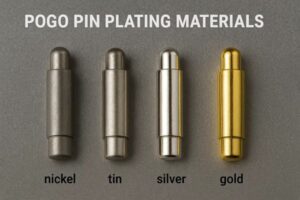
A pogo pin commonly contains several separate parts, such as:- Plunger
- Barrel
- Spring
- Termination
- Insulating housing
- Mating target
The base material and finish of each part should be stated separately.

A general statement such as “beryllium-copper pogo pin” does not identify whether the term refers to the plunger, barrel, spring or another component.
Plating review should include:
- Substrate
- Underlayer
- Contact finish
- Thickness and tolerance
- Hardness
- Porosity
- Tip geometry
- Target finish
- Working stroke
- Sliding or wiping movement
- Environmental exposure
Gold thickness alone cannot establish a one-million-cycle life or a fixed contact-resistance value.Mechanical Endurance Must Match the Real Attachment Motion
Tablet keyboard connectors may experience more than simple axial compression.Possible movements include:
- Axial compression
- Lateral sliding during attachment
- Wiping across the target
- Peeling separation
- Angular attachment
- Keyboard folding
- Side load from hinge movement
- Impact during rapid attachment
Endurance testing should identify:- Tested pogo pin and target
- Working stroke
- Attachment path
- Electrical load
- Cycle rate
- Environmental condition
- Cleaning interval
- Acceptance criteria
- Post-test resistance
- Post-test wear inspection
A mechanical endurance result without electrical load should not automatically be used to represent repeated powered attachment.Bluetooth and Physical Keyboard Interfaces Serve Different Requirements
| Requirement | Bluetooth Keyboard | Physical Pogo Pin Interface |
|---|---|---|
| Cross-device compatibility | May support several compatible devices and operating systems | Usually designed for one tablet family or accessory system |
| Keyboard position | Can operate separately from the tablet | Normally requires physical attachment |
| Keyboard battery | Usually requires an internal battery or another power source | May receive power from the tablet |
| Pairing | Requires a wireless connection process | Can use direct accessory detection |
| Radio environment | Depends on wireless implementation and coexistence | No wireless transport is required for the keyboard channel |
| Mechanical integration | Can be mechanically independent | Requires controlled attachment and contact geometry |
| Replacement accessory | May use generic compatible products | Usually proprietary to the tablet system |
| Contact maintenance | No keyboard-to-tablet electrical contacts | Contacts require inspection and cleaning |
Bluetooth should not be described as inherently defective. A physical interface should be selected because the product requires integrated power, direct attachment, a defined accessory ecosystem or another specific system benefit.When May a Magnetic Pogo Pin Interface Be Appropriate?
| Project Requirement | Possible Value |
|---|---|
| Integrated tablet and keyboard system | The accessory can be automatically recognized when attached |
| No separate keyboard charging routine | The tablet may power the keyboard directly |
| Thin detachable accessory | Flat contacts may reduce the need for a conventional plug and receptacle |
| Keyboard and trackpad data | A project-specific wired channel can connect the accessory to the tablet |
| Controlled product ecosystem | The tablet can identify approved keyboard models or capabilities |
| Repeated attachment | Spring-loaded contacts can compensate for a defined dimensional range |
| Automatic user workflow | Attachment may enable keyboard operation without a separate pairing step |
When May Bluetooth, USB-C or Another Interface Be More Appropriate?
Another interface may be preferable when the project requires:
- Compatibility with many tablet and computer models
- Independent keyboard positioning
- No permanent magnets near magnetic sensors
- A standardized USB data interface
- A widely available replacement cable
- No exposed tablet contacts
- No custom accessory controller or operating-system integration
- Very low custom tooling cost
- A keyboard that operates while physically separated from the tablet
A hybrid system may combine a physical connector for the primary tablet and Bluetooth for use with other devices.Recommended Validation Plan
| Requirement | Possible Evaluation |
|---|---|
| Mechanical architecture | Tablet, keyboard, stand, hinge, support surfaces and center-of-gravity review |
| Working stroke | Minimum, nominal and maximum pogo pin compression |
| Target geometry | Pad dimensions, spacing, flatness, support and wear area |
| Magnetic attachment | Approach, capture, retention, separation and seating impact |
| Partial mating | Offset, tilted, one-contact-first and attached-but-unseated states |
| Keyboard support | Typing, trackpad use, lap use, hinge movement and accidental lifting |
| Electrical path | Contact resistance, voltage drop and temperature rise |
| Accessory power | Normal, peak, backlight and sleep-state power consumption |
| Short circuit | Contact bridging, foreign objects and incorrect attachment |
| Power sequencing | Detection, identification, enable, removal and reconnection |
| Keyboard data | Key input, rollover, recovery and protocol operation |
| Trackpad data | Gesture, click, multi-touch and interruption recovery |
| Signal integrity | Complete connector and PCB channel where higher-speed communication applies |
| End-to-end latency | Actual keyboard event to application or display response |
| Magnetic interaction | Hall sensors, cover detection, orientation and compass behavior where applicable |
| ESD | Exposed contacts, housing and attached or detached operating states |
| Repeated attachment | Project-defined cycles with electrical and mechanical inspection |
| Contamination | Dust, fibres, hand oils, drink residue and metallic debris |
| Cleaning | Approved method followed by complete function verification |
| Protective cases | Approved and foreseeable case thicknesses and geometries |
| Product safety | Complete tablet, keyboard and power architecture under applicable requirements |
Information Required for an Engineering Review
| Requirement Group | Information to Provide |
|---|---|
| Tablet platform | Tablet dimensions, mass, center of gravity and accessory area |
| Keyboard architecture | Folio, kickstand, cantilever, rigid dock or hybrid design |
| Mechanical structure | Hinge, support surfaces, display angles, folding states and removal direction |
| Contact area | Available length, width, position, curvature and restricted regions |
| Pin Map | Power, return, detection, identification, data, shield and service functions |
| Accessory power | Voltage, continuous current, peak current and sleep-state current |
| Keyboard functions | Key matrix, trackpad, backlight, indicators, ports and sensors |
| Communication | Proprietary protocol, USB or another physical layer |
| Power control | Detection, identification, current limiting and removal behavior |
| Magnetic structure | Capture, retention, hinge magnets, cover magnets and restricted zones |
| Magnetic sensors | Hall sensors, cover detection, compass and relevant locations |
| Environment | Dust, oils, liquids, cleaning and intended industrial or consumer use |
| Durability | Expected attachment frequency, folding cycles and product life target |
| Files | 2D drawings, 3D models, PCB layout, schematics and keyboard mechanical concept |
| Commercial | Prototype quantity, production forecast and development stage |
Common Engineering Mistakes
| Mistake | Possible Consequence | Better Approach |
|---|---|---|
| Calling the interface a definitive architectural upgrade | Bluetooth, USB and other valid architectures are ignored | Select the interface from the complete product requirement |
| Calling Bluetooth inherently flawed | The comparison ignores implementation and compatibility requirements | Compare measured product-level performance and user workflow |
| Claiming universal one-millisecond latency | The keyboard scan, firmware, host and display path are ignored | Measure complete end-to-end input latency |
| Assigning USB 2.0 by pin count | The electrical channel and protocol may not meet USB requirements | Validate the complete physical and protocol implementation |
| Using magnets as the only locating structure | Partial seating and uneven compression | Use support surfaces, guides and mechanical stops |
| Using the connector to support tablet weight | Target, PCB and solder-joint damage | Provide an independent structural load path |
| Maximizing magnetic force | High impact, difficult removal and sensor interaction | Balance capture, retention and user handling |
| Claiming zero Hall-sensor interference | External fields and production variation are not evaluated | Test the complete tablet at every supported position |
| Calling host power reverse charging | The accessory power architecture is described inaccurately | Use host-powered accessory unless the circuit actually charges a battery |
| Claiming battery anxiety is eliminated | The tablet battery still powers the accessory | Quantify the keyboard’s effect on the tablet power budget |
| Claiming one-million-cycle life from material selection | Stroke, target, contamination and load conditions are ignored | Report the tested mating system and conditions |
| Calling flat contacts automatically IP67 | The complete enclosure boundary is not tested | Validate the tablet and keyboard assemblies separately |
| Using plating to claim no micro-arcing | Power sequencing and separation under load are ignored | Coordinate mechanical sequence and electrical power control |
Engineering Reference Sources
Final standards, protocol requirements and acceptance criteria should be confirmed for the finished tablet and keyboard product.-
Apple — Smart Connector providing power and data to a keyboard accessory
-
Apple — Magnetic Smart Connector keyboard attachment
-
Apple — Smart Connector cleaning and troubleshooting
-
Microsoft — Magnetic Surface Type Cover attachment and use
-
USB-IF — USB 2.0 electrical compliance testing
-
IEC 60512-2-2 — Contact resistance measurement
-
IEC 60512-9-1 — Mechanical operation endurance without electrical load
-
IEC 60512-28-100 — Connector signal-integrity tests
-
IEC 61000-4-2:2025 — Electrostatic-discharge immunity testing
-
IEC 60529 — Degrees of protection provided by enclosures
-
IEC 62368-1:2023 — Safety requirements for information and communication technology equipment
Frequently Asked Questions
Do magnetic pogo pins make a tablet keyboard faster than Bluetooth?
A physical interface removes the wireless transport from the keyboard path, but total response time also depends on key scanning, firmware, protocol, operating system and display response. The actual products should be measured end to end.Can a three-pin connector transfer keyboard data and power?
A three-contact proprietary interface may be developed for project-specific power and communication, but the required contact count depends on the electrical architecture and protocol.Does a five-pin interface automatically support USB 2.0?
No. USB support requires the correct physical layer, channel geometry, PCB routing, protection, protocol implementation and compliance validation.Can a tablet power the keyboard without a keyboard battery?
Yes, a host-powered architecture may be developed when the tablet provides the required power budget. The keyboard load and its effect on tablet battery life must be evaluated.Is host power the same as reverse charging?
Not normally. When the tablet directly powers keyboard electronics, “host-powered accessory” is more accurate. Reverse charging usually refers to one product charging another product’s battery.Do magnets supports perfect keyboard alignment?
No. Magnets assist capture or retention. Final alignment and pogo pin compression depend on mechanical guides, support surfaces, stops and dimensional tolerances.Can keyboard magnets affect tablet Hall sensors?
They may affect magnetic sensors depending on field strength, direction, distance and sensor design. The complete tablet and keyboard assembly should be evaluated in every supported position.Can flat tablet contacts create an IP67 product?
Flat contacts may simplify part of the enclosure design, but an IP rating must refer to the complete tested tablet or keyboard enclosure.How many attachment cycles can the connector support?
There is no universal value. Life depends on pogo pin construction, working stroke, target finish, mating movement, electrical load, contamination and acceptance criteria.What information is required for a custom tablet keyboard connector review?
Provide the tablet and keyboard models, mechanical architecture, 3D geometry, Pin Map, power budget, communication protocol, magnet restrictions, working-stroke requirements and available drawings.Prepare Your Tablet Keyboard Interface Project
Review

    custom magnetic connector components

when the tablet and keyboard require an integrated magnetic connector pair.

Compare

    pogo pin connector assemblies

when the product already provides mechanical attachment and does not require magnets around the electrical interface.

Additional application and selection resources are available through the

    CTP connector engineering guides
.

Submit the tablet model, keyboard structure, Pin Map, power requirements, communication method and available drawings through the

    Get Quote & Samples page
.


    CTP can review the connector supply scope, contact allocation, pogo pin working stroke, mating targets, magnetic arrangement, PCB or flexible-circuit termination and keyboard mechanical interface. Final protocol compatibility, input latency, host power performance, magnetic-sensor behavior, enclosure protection, product safety and finished-device compliance must be confirmed for the complete customer product.
CTP ENGINEERING PATHS
Choose the right path for your project
Move from application requirements to a connector pair, a data-capable cable assembly, or a charging cable configuration. Final specifications are confirmed against an approved drawing and project validation plan.
Magnetic Connectors
Connector geometry, pin layout, mechanical integration and OEM/ODM review.
Engineering overview → 02Magnetic Data Cables
Power and signal allocation, cable exit, interface selection and assembly review.
Cable engineering → 03Magnetic Charging Cables
Browse the complete cable catalog and shortlist a starting structure for customization.
View cable catalog →