A magnetic pogo pin connector validation plan should connect every product requirement to a defined test, acceptance criterion and traceable record. It should not be a generic list of laboratory equipment or a collection of unrelated test reports.
For a custom connector project, the correct validation scope depends on the device architecture, electrical load, working stroke, magnetic force, cable structure, mounting method and operating environment. A test result from a different connector size, plating system or housing design cannot automatically validate a new product.
This guide explains how engineers can build a practical Design Verification Plan and Report, commonly called a DVP&R, for a magnetic pogo pin connector project.
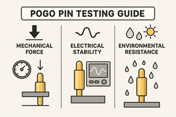
What Is a Magnetic Pogo Pin Connector Validation Plan?
A validation plan is a controlled document that defines:
- What product requirement is being verified
- Which test method will be used
- Which drawing revision and sample lot are included
- What operating and environmental conditions apply
- What measurements are required before, during and after testing
- What constitutes a pass or failure
- Who is responsible for the test and approval
- What evidence must be retained
The purpose is not to prove that a connector is universally reliable. The purpose is to demonstrate that a defined connector design meets the requirements of a defined application.
A useful DVP&R links each engineering requirement to a test condition, measurement method, sample group, acceptance limit and final result.
Why a Generic Connector Test List Is Not Enough
Two magnetic connectors may use the same number of pogo pins but require completely different validation plans.
For example:
- A wearable charging interface may be affected by sweat, skin oils, frequent handling and limited installation space.
- An industrial fixture may require high cycle frequency, replaceable contact modules and continuous resistance monitoring.
- A medical device may require controlled cleaning compatibility and application-specific risk documentation.
- An outdoor device may require sealing validation after mechanical cycling and temperature exposure.
- A data interface may require signal-integrity measurements that are unnecessary for a power-only connector.
Testing every connector with the same current, cycle count, humidity duration and force limit may create reports that look complete but do not represent the actual device.
Step 1: Freeze the Engineering Inputs
Testing should not begin until the important product inputs have been defined. Otherwise, the laboratory may validate conditions that do not match the final assembly.
The input package should include:
| Input Category | Required Information | Why It Matters |
|---|---|---|
| Electrical | Voltage, current per contact, duty cycle, signal type and grounding arrangement | Determines resistance, temperature-rise, insulation and signal tests |
| Mechanical | Free height, working height, stroke, pitch, alignment tolerance and mechanical stops | Determines contact force, wear and risk of bottoming out |
| Magnetic | Holding direction, target force, breakaway behavior, polarity and available air gap | Determines capture, alignment and release validation |
| Environmental | Temperature, humidity, dust, water, sweat, oils, cleaning agents and vibration | Defines relevant environmental conditioning |
| Assembly | PCB mounting, soldering process, housing retention, cable termination and strain relief | Identifies failures outside the pogo pin itself |
| Service Life | Expected mating frequency, operating years and maintenance conditions | Establishes durability and inspection requirements |
Unknown requirements should be recorded as open items. They should not be silently replaced with a supplier’s standard value.
Step 2: Convert Requirements into Critical-to-Quality Characteristics
Critical-to-quality characteristics, or CTQs, are measurable product features that directly affect function, safety, assembly or user experience.
For a magnetic pogo pin connector, typical CTQs may include:
- Contact resistance at the defined working stroke
- Voltage drop across the complete power path
- Temperature rise at the specified current and duty cycle
- Spring force at minimum, nominal and maximum compression
- Magnetic holding force in the intended pull direction
- Breakaway force under cable loading
- Connector alignment at final magnetic engagement
- Housing and insert retention
- Insulation between adjacent contacts
- Cable strain-relief performance
- Resistance to the specified operating environment
Each CTQ should have a drawing requirement, project specification or approved engineering limit. Statements such as “high current,” “strong magnet” and “low resistance” are not measurable acceptance criteria.
Step 3: Separate Design Verification from Production Quality Control
One of the most common validation mistakes is treating every test as a routine production inspection.
Connector testing should normally be divided into three levels.
Design Verification
Design verification determines whether the selected materials, geometry and architecture can meet the project requirements.
Examples include:
- Electrical load and temperature-rise evaluation
- Working-stroke and force-curve verification
- Mechanical operation and wear evaluation
- Magnetic capture and breakaway testing
- Environmental conditioning
- Vibration or shock testing where required
- Ingress testing for the assembled enclosure
Process Validation
Process validation determines whether the approved design can be manufactured repeatedly using the intended tooling, assembly process and production equipment.
Examples include:
- First-article dimensional inspection
- Soldering or termination evaluation
- Magnet position and polarity verification
- Adhesive or insert-molding process confirmation
- Cable crimping, welding or overmolding verification
- Assembly fixture and measurement-system confirmation
Routine Production Control
Routine production control monitors selected CTQs during mass production. It should not attempt to repeat every destructive qualification test on every batch.
Suitable production checks may include:
- Critical dimensions
- Continuity and short-circuit inspection
- Selected resistance measurements
- Spring movement or force sampling
- Magnet polarity and position
- Appearance and plating condition
- Cable pull or retention sampling
- Packaging and traceability review
Step 4: Build a Requirement-to-Test Matrix
The DVP&R should show how each engineering requirement will be verified. The following example illustrates the structure. Test limits and sample quantities must be defined for the individual project.
| Requirement | Verification Method | Pre-Test Measurement | Post-Test Measurement | Acceptance Basis |
|---|---|---|---|---|
| Stable power contact | Contact resistance and voltage-drop measurement | Baseline resistance by sample | Resistance drift and abnormal variation | Approved electrical specification |
| Safe current path | Rated-current temperature-rise test | Ambient temperature and initial resistance | Stabilized temperature and voltage drop | Project thermal limit |
| Correct pogo pin compression | Working-height and force measurement | Free height and force curve | Force change and return movement | Drawing-defined stroke window |
| Controlled magnetic mating | Capture, holding and breakaway-force test | Initial force and air gap | Force retention and physical condition | Device use requirement |
| Housing integrity | Insert-retention or mechanical-load test | Initial dimensions and position | Displacement, cracking or release | Mechanical drawing |
| Environmental suitability | Project-specific conditioning | Electrical and mechanical baseline | Functional and visual comparison | Application specification |
| Enclosure protection | Ingress-protection test on the assembled device | Seal and assembly inspection | Ingress result and post-test function | Required enclosure rating |
Step 5: Define Sample Groups Before Testing
Not every test should be performed sequentially on the same samples.
Some tests are destructive. Others permanently change the connector and may influence later results. For example, a connector exposed to aggressive environmental conditioning should not automatically be used as the baseline sample for dimensional capability evaluation.
A practical validation program may divide samples into groups such as:
- Group A: Dimensional, electrical and mechanical baseline measurements
- Group B: Mechanical operation and wear evaluation
- Group C: Temperature, humidity or other environmental conditioning
- Group D: Vibration, shock or cable-load testing
- Group E: Ingress or sealing evaluation on the final enclosure
- Group F: Retained reference samples for comparison and failure analysis
The DVP&R should identify whether samples come from prototypes, pilot production or normal production tooling. Results from hand-built samples may not fully represent a future production process.
Step 6: Control the Test Sequence
Test sequence can affect the final conclusion. A connector that passes individual tests may behave differently when tests are performed in a realistic sequence.
A common engineering sequence is:
- Confirm drawing revision and sample traceability
- Perform visual and dimensional inspection
- Record electrical and mechanical baseline values
- Apply the planned mechanical or environmental conditioning
- Monitor function during testing where required
- Allow the specified recovery or stabilization period
- Repeat electrical, mechanical and visual measurements
- Compare individual sample change against the acceptance criteria
- Document failures, abnormal trends and corrective actions
Where combined environmental and dynamic exposure is important, the validation team should determine whether sequential testing or combined-condition testing better represents the actual device. IEC 60068 includes methods and guidance for combined climatic and dynamic conditions, but the project specification must still define the applicable severity.
Step 7: Validate the Electrical Path as a System
A magnetic connector is more than a pogo pin. The complete electrical path may include:
- Pogo pin plunger and barrel
- Internal spring
- Contact pad or mating plate
- PCB pad and solder joint
- Wire, crimp, weld or solder termination
- Cable connector or external interface
Measuring only the discrete pogo pin may miss failures caused by the PCB, cable or mating pad.
Depending on the project, electrical validation may include:
- Contact resistance across the mated interface
- Voltage drop under the specified current
- Temperature rise after stabilization
- Continuity during movement or vibration
- Insulation between adjacent contacts
- Dielectric testing where required by the product specification
- Signal-integrity evaluation for data interfaces
IEC 60512-2-2 provides a standardized method for measuring resistance across mated contacts. The project should still define the actual sample configuration, measuring points and acceptance limit.
Step 8: Validate Magnetic and Mechanical Behavior Separately
Magnetic force and pogo pin spring force are different design parameters.
Magnetic force influences:
- Initial capture
- Final alignment
- Holding strength
- Breakaway behavior
- User feel
Pogo pin spring force influences:
- Contact pressure
- Electrical stability
- Wear rate
- Housing load
- Return movement
A connector may have strong magnetic attraction but insufficient pogo pin compression. It may also have adequate electrical contact but excessive holding force for the intended breakaway function.

Mechanical validation should therefore distinguish between:
- Magnetic holding force
- Connector separation force
- Cable pull direction
- Pogo pin spring force
- Housing retention force
- Insert or terminal retention
IEC 60512-13-1 describes measurement of engaging and separating forces, while IEC 60512-15-2 addresses axial retention of a connector insert in its housing. Applicability depends on the connector construction and the detailed product specification.
Step 9: Treat Environmental Testing as Application-Specific
Environmental testing should reproduce relevant field risks rather than adding every available laboratory test to the plan.
Potential exposure conditions include:
- High or low operating temperature
- Temperature cycling
- Condensing or non-condensing humidity
- Vibration and mechanical shock
- Dust, water or temporary immersion
- Sweat, oils or cleaning agents
- Industrial contamination
- Storage and transportation conditions
IEC 60068 contains environmental test methods for components and equipment, including humidity and combined climatic/dynamic conditions. The required temperature, duration, cycle count and operating state must come from the product requirement, not from a generic connector claim.
IP Rating Is Not a Pogo Pin Test Result
An IP rating applies to the protection provided by an enclosure under defined conditions. It does not automatically describe:
- Pogo pin contact resistance
- Mechanical cycle life
- Magnetic force
- Cable durability
- Resistance to sweat or cleaning chemicals
A connector used in an IP-rated product should normally be evaluated as part of the assembled enclosure, including the housing, seals, adhesive, fasteners and manufacturing process.
IEC 60529 defines enclosure ingress-protection classifications. A project claiming a particular IP level should identify the final assembly and test condition covered by the result.
Step 10: Define Pass and Failure Criteria Before Testing
A test is incomplete when the report only states that samples were exposed to a condition.
Before testing begins, define:
- Maximum permitted resistance or resistance change
- Maximum permitted temperature rise
- Allowed force range
- Permitted dimensional change
- Maximum interruption duration, where applicable
- Visual conditions considered unacceptable
- Requirements for post-test operation
- Rules for sample failure, retest and investigation
Results should be reported by individual sample. Reporting only an average can hide one connector that has already failed or is close to the acceptance limit.
Step 11: Confirm the Measurement System
A validation result is only useful when the measurement method is controlled.
The test record should identify:
- Equipment name and identification number
- Calibration status
- Fixture configuration
- Measurement points
- Test current or load
- Sampling rate where dynamic events are monitored
- Ambient or chamber conditions
- Operator or responsible engineer
- Software or data-acquisition version where relevant
For low-resistance measurements, fixture resistance, lead resistance and probe location may significantly influence the reading. The selected method should be repeatable and documented.
Step 12: Link Validation to Production Documentation
After the design is approved, the important validation outputs should be transferred into production controls.
Relevant documents may include:
- Approved product drawing
- Bill of materials
- Control plan
- Incoming inspection criteria
- Process work instructions
- First-article inspection report
- Production test specification
- Packaging and traceability requirements
- Change-control requirements
The validated sample and the mass-produced product should use the same controlled materials, geometry and manufacturing process unless an approved change is introduced.
When Is Revalidation Required?
Revalidation should be considered when a change may affect a previously verified requirement.
Typical triggers include:
- Changing the pogo pin supplier or internal spring construction
- Changing plating material or plating specification
- Changing the magnet material, dimensions or coating
- Changing housing resin, adhesive or sealing structure
- Changing cable gauge, conductor, insulation or termination
- Changing PCB finish or mating-pad geometry
- Changing working height or compression stroke
- Changing tooling, assembly equipment or production location
- Increasing current, voltage or environmental requirements
- Receiving a field failure related to the connector interface
Revalidation does not always mean repeating the complete original plan. The engineering team should assess which requirements are affected and document the reason for the selected retest scope.
Recommended DVP&R Report Fields
A practical connector DVP&R should include the following fields:
| Field | Required Record |
|---|---|
| Requirement ID | Reference to drawing, specification or risk document |
| Requirement | Measurable function or performance target |
| Test Method | Internal method, customer method or applicable standard |
| Sample Information | Quantity, lot, revision and manufacturing stage |
| Conditions | Load, stroke, speed, temperature, humidity and duration |
| Acceptance Criteria | Approved pass and failure limits |
| Result | Individual measurements and observations |
| Status | Pass, fail, open or retest required |
| Evidence | Report, raw data, photographs and equipment record |
| Approval | Responsible engineering and quality review |
Engineering Reference Standards
The following standards can provide test-method references. The applicable edition and test severity should be confirmed for each project.
- IEC 60512-2-2: Contact resistance measurement
- IEC 60512-13-1: Engaging and separating forces
- IEC 60512-9-1: Mechanical operation endurance without electrical load
- IEC 60512-99-002: Mechanical operations under electrical load
- IEC 60512-15-2: Connector insert retention in housing
- IEC 60068-2-53: Combined climatic and dynamic testing
- IEC 60068-2-30: Cyclic damp heat testing
- IEC 60529: Degrees of protection provided by enclosures
Frequently Asked Questions
Does every magnetic pogo pin connector need the same validation tests?
No. The validation plan should reflect the connector’s electrical load, mechanical structure, expected use, assembly method and operating environment.
Can a supplier’s standard test report validate a custom connector?
Only when the tested construction, materials, dimensions, working stroke and conditions are sufficiently representative of the custom product. Differences should be reviewed and documented.
Should all tests be performed on the same samples?
Not necessarily. Some tests are destructive or may influence later results. Sample groups should be allocated according to the test sequence and engineering objective.
Is final inspection the same as product validation?
No. Final inspection verifies selected production characteristics. Product validation demonstrates that the design meets defined application requirements under specified conditions.
Does an IP68 result prove long-term connector reliability?
No. An IP result addresses enclosure ingress protection under defined conditions. Mechanical life, contact resistance, temperature rise and environmental compatibility require separate evaluation.
What information is required before CTP reviews a validation plan?
Provide the application, pin map, voltage, current, working height, expected mating frequency, magnetic-force requirement, environmental conditions, cable structure and available 2D or 3D files.
Prepare Your Connector Validation Inputs
Before requesting samples, prepare a concise engineering input package containing:
- Application and device description
- Pin allocation and electrical requirements
- Available connector envelope
- Working height and tolerance stack-up
- Expected mating and release direction
- Magnetic holding or breakaway requirement
- Service-life requirement
- Environmental and sealing requirements
- PCB, cable and mounting information
- Required validation documents
Review available custom magnetic connector structures, visit the engineering guides, or submit your drawing and project requirements through the Get Quote & Samples page.
CTP can review the connector geometry, electrical path, magnetic structure and proposed validation scope before prototype development. Final test conditions and acceptance criteria should be confirmed in the approved project specification.
CTP ENGINEERING PATHS
Choose the right path for your project
Move from application requirements to a connector pair, a data-capable cable assembly, or a charging cable configuration. Final specifications are confirmed against an approved drawing and project validation plan.
Magnetic Connectors
Connector geometry, pin layout, mechanical integration and OEM/ODM review.
Engineering overview → 02Magnetic Data Cables
Power and signal allocation, cable exit, interface selection and assembly review.
Cable engineering → 03Magnetic Charging Cables
Browse the complete cable catalog and shortlist a starting structure for customization.
View cable catalog →