OEM / ODM Custom Interconnect Solutions
CTP Finished Cable Engineering

Custom Magnetic Cable Assemblies for Power, Data and Signal

A magnetic cable assembly combines a source-side interface, conductors, jacket, shielding where required, strain relief, overmold and a magnetic connector head. CTP develops finished assemblies around the device pin map, power requirement, protocol or signal function, cable length, routing, flexibility, sealing boundary and validation plan. Charging, data and signal capability must be confirmed for the complete cable and its approved test conditions—not inferred from the connector shape or USB interface alone.

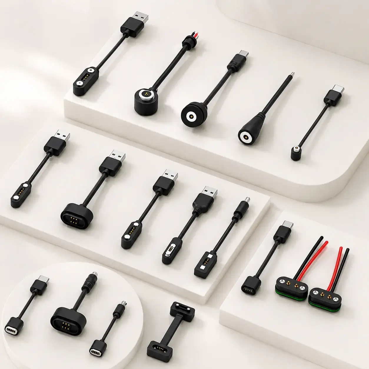
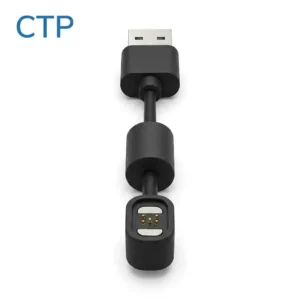
CTP custom magnetic charging and data cable assembly product range for OEM devices
Representative finished cable assemblies. Connector head, pin map, cable construction and electrical values are confirmed for the approved project.

Complete Product Catalog

Browse All Magnetic Cable Assemblies

All published cable assembly product records are shown below. Filter by contact count or round structure without leaving this page.

Loading products
No products match this filter. Choose “All” to return to the complete catalog.

Function Definition

Charging Cable, Data Cable or Hybrid Assembly?

Define the electrical functions before selecting pin count or appearance. A reliable cable architecture starts from the required current path, signal allocation, source-side interface and device-side magnetic mating structure.

01

Magnetic Charging Cable

Designed around the required power and ground path, voltage drop, current, duty cycle and temperature-rise plan.

02

Magnetic Data Cable

Adds a defined protocol or signal pin map, conductor and shielding review, continuity and interface validation.

03

Power + Data / Signal

Allocates separate contacts and cable conductors for power, ground, data, control, detection or identification.

Custom Options

Build the Cable Around the Device Interface

Each option affects manufacturability, performance and validation. The project drawing and cable specification remain the controlling documents.

Source-Side Interface

USB-A, USB-C, DC, bare wire or another customer-defined termination.

Magnetic Head

Round, rectangular, bar-style, keyed, low-profile or application-specific housing.

Pin Map & Function

2–6 pin or multi-pin allocation for power, ground, data, signal and identification.

Cable Construction

Length, conductors, shielding, jacket, flexibility, color, exit direction and strain relief.

Electrical Requirements

Voltage, current, protocol, contact path, voltage drop and temperature-rise conditions.

Mechanical Requirements

Retention, release direction, pull, bend, routing, device fit and user interaction.

Environmental Requirements

Sealing boundary, corrosion, chemicals, temperature, humidity and use environment.

Appearance & Supply Scope

Color, logo, packaging, device receptacle, cable assembly and documentation scope.

Engineering Checklist

Information Required for a Cable Proposal

Providing the following information reduces repeated assumptions between purchasing, device engineering and the cable manufacturer.

InputProject InformationEngineering Decision
Device & ApplicationEquipment type, operating environment, mating behavior and routingCable architecture and connector-head structure
Source InterfaceUSB-A, USB-C, DC, bare wire or customer interfaceTermination, molding and protocol responsibility
Electrical FunctionVoltage, rated/peak current, data or signal requirements, duty cyclePin map, conductors, shielding and validation plan
Mechanical LayoutHead shape, available space, cable exit, mating direction and retention targetOvermold, magnet arrangement and strain relief
Cable ConstructionLength, flexibility, jacket, color, diameter and routing constraintsConductor and material proposal subject to approved specification
ReliabilityPull, bend, mating, sealing, corrosion, environmental and regulatory needsApplicable test conditions, samples, acceptance criteria and report scope

Cable Development

Control the Entire Electrical and Mechanical Load Path

The magnetic breakaway function does not replace cable strain relief. Cable routing, overmold, conductor termination and connector retention must be considered as one system.

Define Functions

Power, ground, data, signal, detection and source interface.

Design the Assembly

Magnetic head, pin map, cable, shielding, overmold and exit direction.

Confirm Documents

Drawing, cable specification, materials, tolerances and labeling.

Validate Samples

Electrical, mechanical and environmental items for the actual model.

Release Production

Approved standards, inspection points, traceability and packaging.

Reliability Planning

Validation Must Match the Cable and Use Condition

Typical project plans can include continuity, contact resistance, voltage drop, insulation, withstand voltage, temperature rise, pull, bending, mating, sealing, salt spray, temperature or humidity exposure. Applicable standards, sample state, duration, load and acceptance criteria must be documented for the specific model.

Electrical Path

Verify pin definition, continuity, resistance, voltage drop, insulation and temperature conditions.

Mechanical Path

Review connector retention, release, pull, bend, cable exit and overmold integrity.

Environmental Boundary

Define sealing, corrosion, chemicals, temperature and humidity for the intended use.

Frequently Asked Questions

Magnetic Cable Assembly FAQ

What can be customized on a magnetic cable assembly?
The source-side interface, magnetic head shape, pin count, pin map, voltage, current, data or signal function, cable length, conductor construction, jacket, shielding, color, strain relief, sealing, logo and packaging can be reviewed for the project.
What is the difference between a magnetic charging cable and a magnetic data cable?
A charging cable is primarily designed around the required power path. A data cable also requires a defined signal pin map, protocol-related conductor and shielding review, continuity verification and interface validation.
Can USB-A and USB-C source-side interfaces be supplied?
USB-A, USB-C, DC, bare-wire and other source-side terminations may be evaluated. The interface does not by itself define the supported charging or data protocol; the complete electrical design must be confirmed.
How should cable length and wire gauge be selected?
Cable length and conductor construction affect voltage drop, temperature rise, flexibility, routing and signal performance. Selection must use the project current, duty cycle, environment and approved validation conditions.
Which tests can be planned for a magnetic cable assembly?
Typical project plans may include continuity, contact resistance, voltage drop, insulation, withstand voltage, temperature rise, pull, bending, mating, sealing, corrosion or environmental tests. Applicable methods and acceptance criteria are confirmed for the model.

Discuss a Custom Magnetic Cable Assembly

Send the device application, source interface, pin map, voltage and current, data or signal requirement, cable length, sealing target, forecast quantity and available drawings.

Phone / WhatsApp: +86 136 0265 2557Email: bella@ytanpogo.com
Submit Cable Requirements