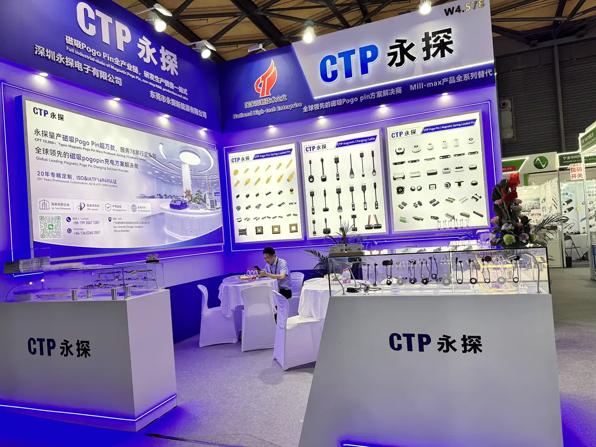
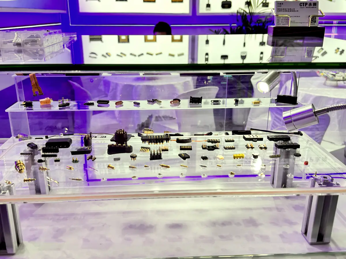
OEM / ODM Custom Interconnect Solutions
CTP Custom Interconnect Engineering

Custom Magnetic Connectors for OEM Devices

A magnetic connector combines spring-loaded electrical contacts, magnets, insulation and a mechanically guided mating interface. CTP develops device-side magnetic connectors around the approved pin map, voltage and current, signal function, available space, mating direction, PCB or wire termination, sealing boundary and validation plan. The result is not selected by appearance alone: every project must connect the device architecture, electrical load and mechanical integration.

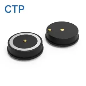
CTP round male and female magnetic connectors for OEM devices
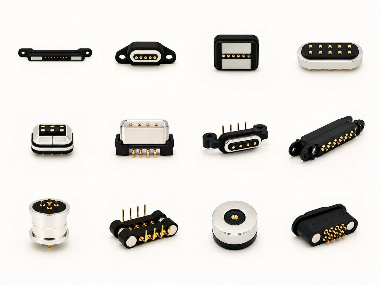
Representative CTP magnetic connector structures. Final dimensions, materials and electrical ratings are confirmed by the approved project drawing.

Complete Product Catalog

Browse All Magnetic Connectors

All published connector product records are shown below. Filter by contact count or round structure without leaving this page.

Loading products
No products match this filter. Choose “All” to return to the complete catalog.

Product Definition

Magnetic Connector or Magnetic Cable Assembly?

Use a connector when the project needs the magnetic mating interface, receptacle, PCB-mounted contact structure or wire-terminated magnetic head. Choose a complete cable assembly when the supply scope must also include cable conductors, source-side interface, shielding, jacket, strain relief and finished-cable validation.

01

Magnetic Connector

Focuses on the magnetic mating interface and device integration.

  • Male and female mating structures
  • PCB, FPC, solder or wire termination
  • Custom housing, insulation and magnet arrangement
  • Power, ground, data, signal or identification contacts
02

Magnetic Cable Assembly

Includes the connector head plus the complete cable construction.

  • USB-A, USB-C, DC, bare wire or custom input
  • Cable length, conductor, jacket and shielding
  • Overmold and strain-relief design
  • Finished cable continuity and project validation

Selection Routes

Select the Structure by Device Requirements

The categories below are engineering starting points. They do not replace a drawing review or model-specific specification.

01

Round Connectors

Useful where rotational alignment, compact diameter or circular industrial design is preferred.

02

Rectangular & Bar-Style

Supports directional mating, linear pin layouts and space-constrained device edges.

03

2–6 Pin & Multi-Pin

Pin count follows the required power, ground, data, signal and identification functions.

04

Sealed & Custom Structures

Housing, gasket, potting and device-side sealing boundaries are reviewed as a complete interface.

Engineering Inputs

Parameters Required Before Connector Design

CTP uses these inputs to evaluate contact allocation, magnetic arrangement, housing geometry and the validation scope. Numerical values are only published when they belong to a specific model and documented condition.

Engineering ItemWhat the Customer Should ProvideWhat CTP Confirms
Application & EnvironmentDevice type, installation position, user interaction, operating environmentSuitable connector architecture and validation boundary
Pin Map & FunctionPower, ground, data, signal, detection or identification requirementsContact allocation, polarity and mating orientation
Voltage & CurrentRated and peak conditions, duty cycle, charging methodContact structure, conductor path and temperature-rise plan
Mechanical EnvelopeAvailable space, mating direction, alignment tolerance, device drawingsHousing geometry, magnet arrangement and mounting method
TerminationPCB, FPC, wire, solder, connector or cable assembly scopeDevice-side and supply-scope interface details
Sealing & ReliabilityIngress target, chemicals, cycles, pull, vibration and environmental conditionsApplicable test items, method, samples and acceptance criteria

Development Route

From Requirements to an Approved Production Drawing

A repeatable development route keeps electrical, mechanical and manufacturing assumptions visible to both engineering and procurement teams.

Requirement Review

Application, pin map, voltage, current, space and supply scope.

Structure Proposal

Geometry, magnets, contacts, insulation, mounting and cable interface.

Drawing Confirmation

Dimensions, tolerances, materials, pin definition and responsibility boundary.

Sample Validation

Project-specific electrical, mechanical and environmental checks.

Production Control

Approved specification, inspection points, traceability and packaging.

Application Engineering

Designed Around the Device, Not a Generic Claim

Magnetic connectors are used in wearables, medical equipment, smart home devices, consumer electronics, robotics, industrial equipment, automotive accessories and other OEM products. Each application changes the acceptable connector size, user force, cable route, sealing boundary, signal requirement and validation method.

Compact User Devices

Prioritize available space, blind mating, user interaction and repeated connection.

Industrial & Robotic Equipment

Review alignment, contamination, vibration, service access and automated docking.

Medical & Regulated Equipment

Define cleaning, material, risk, documentation and validation requirements for the specific device.

Frequently Asked Questions

Magnetic Connector FAQ

What information is required for a custom magnetic connector?
Provide the device application, available envelope, mating direction, pin map, voltage, current, signal requirements, PCB or wire termination, sealing target, cable or receptacle scope, and any available 2D or 3D drawings.
Can magnetic connectors carry both power and data?
Yes, a custom pin map may allocate separate contacts for power, ground, data, signal or identification. The final allocation, spacing, shielding and test method must be confirmed for the actual protocol and approved drawing.
How is the magnetic retention force selected?
Retention force is chosen together with connector size, mating direction, user interaction, cable routing, magnet arrangement and device safety requirements. A larger magnetic force is not automatically a better design.
Are waterproof magnetic connectors available?
Sealing can be designed around the connector housing, device receptacle and assembly interface. The required ingress level, test condition and responsibility boundary must be confirmed for each project.
Does CTP provide samples before production?
Sample scope and validation items are defined after the electrical and mechanical requirements are reviewed. Production specifications follow the customer-approved drawing and project confirmation.

Discuss a Custom Magnetic Connector

Send the device application, Pin Map, voltage and current, available space, mating direction and available drawings for engineering review.

Phone / WhatsApp: +86 136 0265 2557Email: bella@ytanpogo.com
Submit Project Requirements