
Custom Magnetic Connectors for Automotive Electronics & E-Mobility
CTP develops custom magnetic pogo pin connectors and magnetic cable assemblies for low-voltage vehicle electronics, removable modules, charging docks and light electric mobility equipment. Each design is reviewed around current, voltage, vibration, temperature, sealing, mounting space and breakaway-force requirements.
- Custom pin layout
- Power, signal and selected data
- PCB, FPC and cable mounting
- Prototype and engineering review
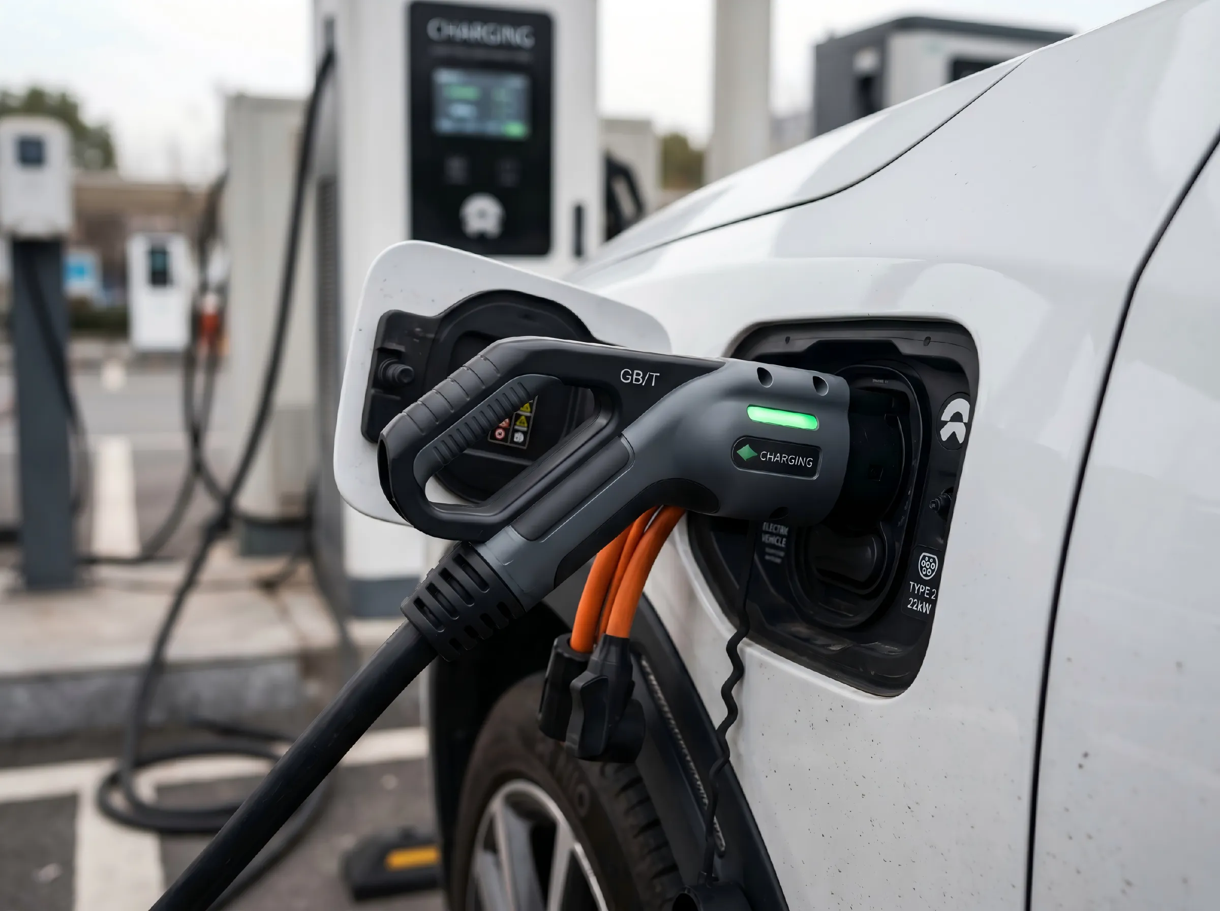
What Is an Automotive Magnetic Connector?
An automotive magnetic connector combines self-alignment or controlled breakaway behavior with spring-loaded contacts for power, ground, signal or selected data channels. It can reduce manual alignment, support repeated docking and simplify the connection of removable vehicle modules.
The correct design depends on the full system—not only the pogo pin. Contact geometry, conductor size, magnet arrangement, housing retention, cable strain relief, sealing and installation tolerance must be evaluated together.
Six Factors That Determine Connector Reliability
Automotive and mobility projects require the connector to be designed around electrical load, motion, environment and installation constraints.
Current, Voltage & Temperature Rise
Provide continuous current, peak current, system voltage, duty cycle and allowable temperature rise. Pin count, contact geometry, conductor size and cable length must be evaluated as one electrical path.
Vibration & Contact Stability
Spring force, working compression, side-load control, mounting rigidity and housing tolerances influence dynamic contact resistance and the risk of intermittent connection.
Temperature & Material Selection
Operating and storage temperatures affect springs, plastics, magnets, adhesives, overmolding and cable jackets. The required range must be defined before material selection and validation.
Water, Dust & Corrosion
Water resistance depends on the complete mated interface and device housing. Humidity, condensation, road splash, salt exposure and cleaning requirements should be specified during the design review.
Magnetic Holding & Breakaway Force
Magnet grade, size, spacing and mechanical guidance determine holding force and release behavior. The target should be defined in newtons and verified on the final assembly.
Mounting, Tolerance & Service Life
PCB, FPC, wire and cable mounting options require different strain relief, soldering and alignment controls. Mating cycles and maintenance access should also be included in the project specification.
Where Magnetic Pogo Pin Interfaces Can Be Evaluated
The following are potential application directions rather than fixed off-the-shelf specifications. Each project requires a separate electrical and mechanical review.
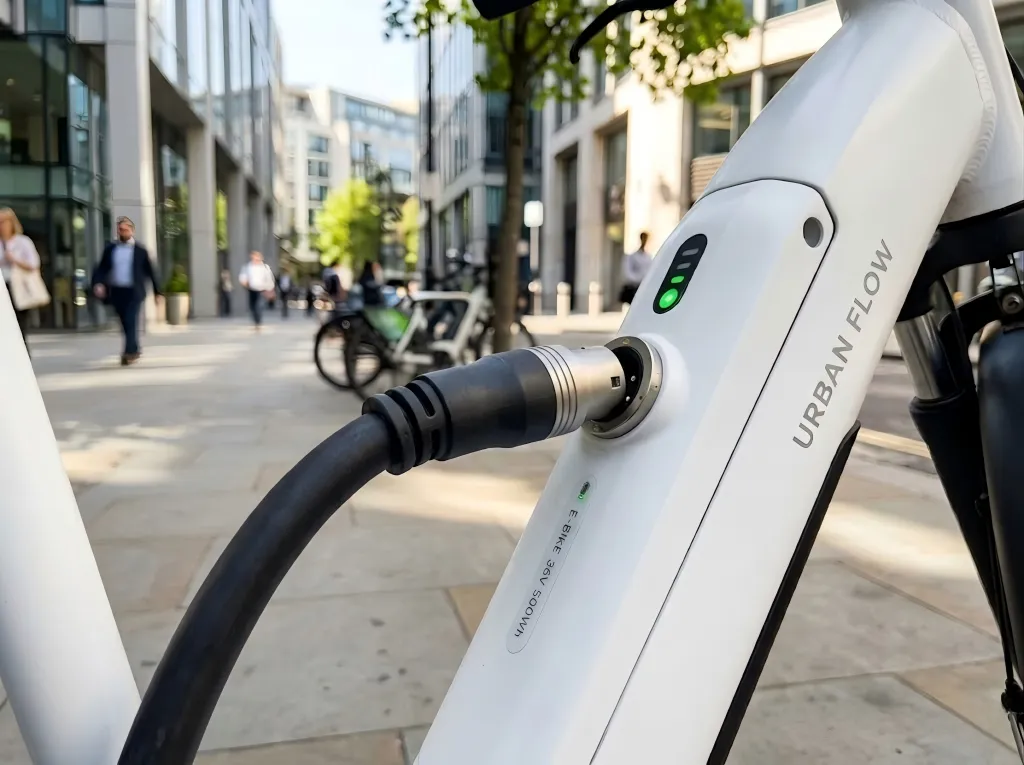
E-Bikes, Scooters & Removable Modules
Custom magnetic charging or docking interfaces can be evaluated for removable batteries, control modules and service connections when the required current, voltage, temperature rise and release behavior are clearly defined.

Displays, Controllers & In-Cabin Modules
Magnetic pogo pin connectors can simplify blind mating and repeated docking for displays, controllers, diagnostic tools and removable interior electronics, subject to vibration and retention validation.
Information Needed for an Automotive Connector Review
Supplying these inputs early helps reduce repeated revisions and makes the prototype proposal more relevant to the actual installation.
| Project input | What to provide | Why it matters |
|---|---|---|
| Electrical load | Continuous current, peak current, voltage, duty cycle and pin assignment | Determines contact structure, conductor size and temperature-rise validation |
| Mechanical space | 2D/3D drawing, mating area, PCB/FPC position and allowable connector height | Defines housing dimensions, pitch, alignment and mounting method |
| Magnetic behavior | Target holding force, release direction and acceptable breakaway behavior | Guides magnet layout and mechanical retention design |
| Environment | Temperature, humidity, water, dust, salt, cleaning and chemical exposure | Influences material, plating, sealing and test planning |
| Dynamic conditions | Vibration, shock, cable movement, side load and mounting rigidity | Helps define spring force, compression and contact-stability tests |
| Project volume | Prototype quantity, pilot quantity and expected annual volume | Supports tooling, process and production-planning decisions |
From Requirements to Production Validation
Submit Requirements
Send drawings, pin assignment, electrical load, environment and volume information.
Engineering & DFM Review
Review connector structure, contact compression, magnets, mounting and cable design.
Prototype & Project Tests
Produce samples and agree on the tests needed for the actual application conditions.
Pilot & Mass Production
Finalize drawings, inspection criteria, process controls and production requirements.
Continue Your Connector Selection
Automotive Magnetic Connector Questions
Can one magnetic connector carry power and signals?
Yes. Separate contacts can be assigned to power, ground, detection, control or selected signal functions. Pin assignment, spacing and isolation must be reviewed against the electrical requirements.
Can holding force and breakaway behavior be customized?
Yes. Magnet dimensions, grade, arrangement, air gap and mechanical guidance can be adjusted. The required holding and release force should be defined in newtons and verified on the final assembly.
Are waterproof automotive magnetic connectors available?
Water-resistant structures can be evaluated, but the final protection level depends on the mated connector, housing, cable outlet and device installation. The complete assembly must be tested for the target use.
What testing should be considered?
Typical project validation may include contact resistance, temperature rise, mating durability, holding force, cable pull, vibration, shock, temperature cycling, humidity, corrosion and water/dust protection. The final test plan should follow the customer's product requirements.
What files should I send for a design review?
Send a 2D or 3D drawing, installation space, pin assignment, current and voltage, target holding force, mounting method, operating environment, prototype quantity and expected annual volume.