
Custom Magnetic Connector & Pogo Pin Case Studies
Review how different device constraints lead to different magnetic connector, magnetic cable and pogo pin architectures. Each case is organized around the project challenge, selected interface concept, design trade-offs and the validation questions that should be checked before transferring the pattern to another OEM or ODM device.
- Compact wearable interfaces
- Water, sweat and cleaning exposure
- Power plus additional channels
- High-load cable architecture
Eight Application Patterns Across Wearables, Personal Care, IoT, Audio and Mobility
Every card highlights the main engineering question rather than presenting one fixed connector specification as suitable for every device.
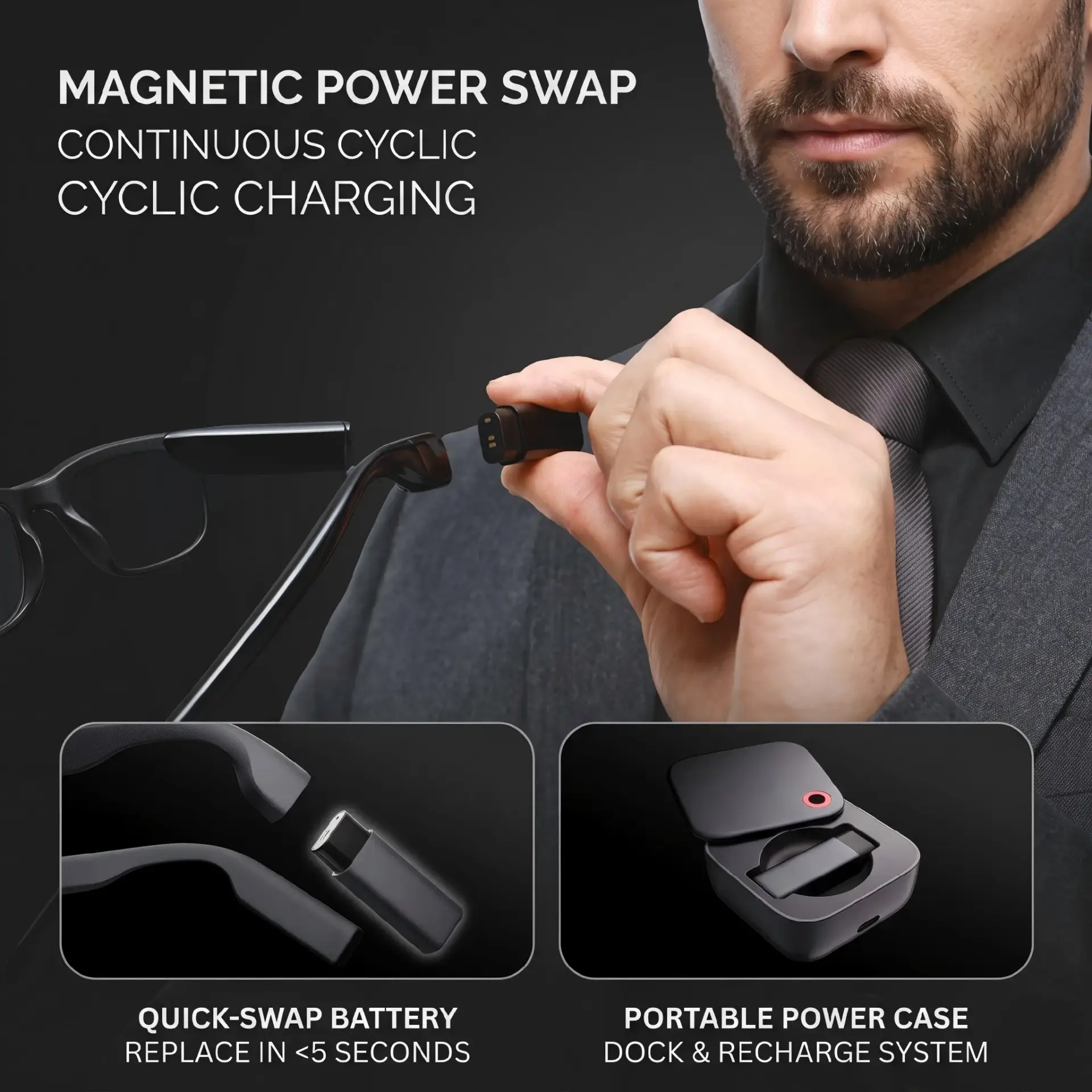
AR Smart Glasses Magnetic Connector
A compact multi-contact interface pattern for a narrow wearable enclosure where connector height, sweat exposure, blind mating and PCB integration must be reviewed together.
Read AR Smart Glasses Case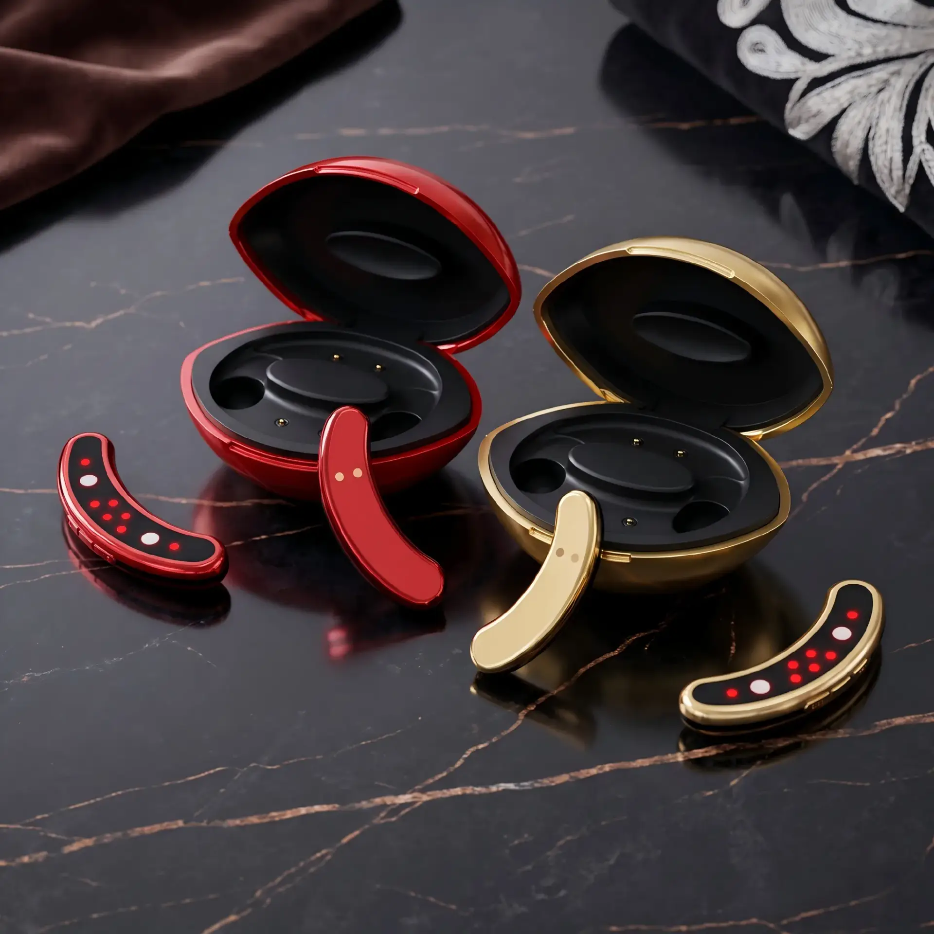
Facial Beauty Device Charging Interface
A charging-interface pattern for equipment exposed to wiping, cosmetics, humidity or liquid splash, where the flat external surface and device-side sealing strategy are part of the same design.
Read Beauty Device Case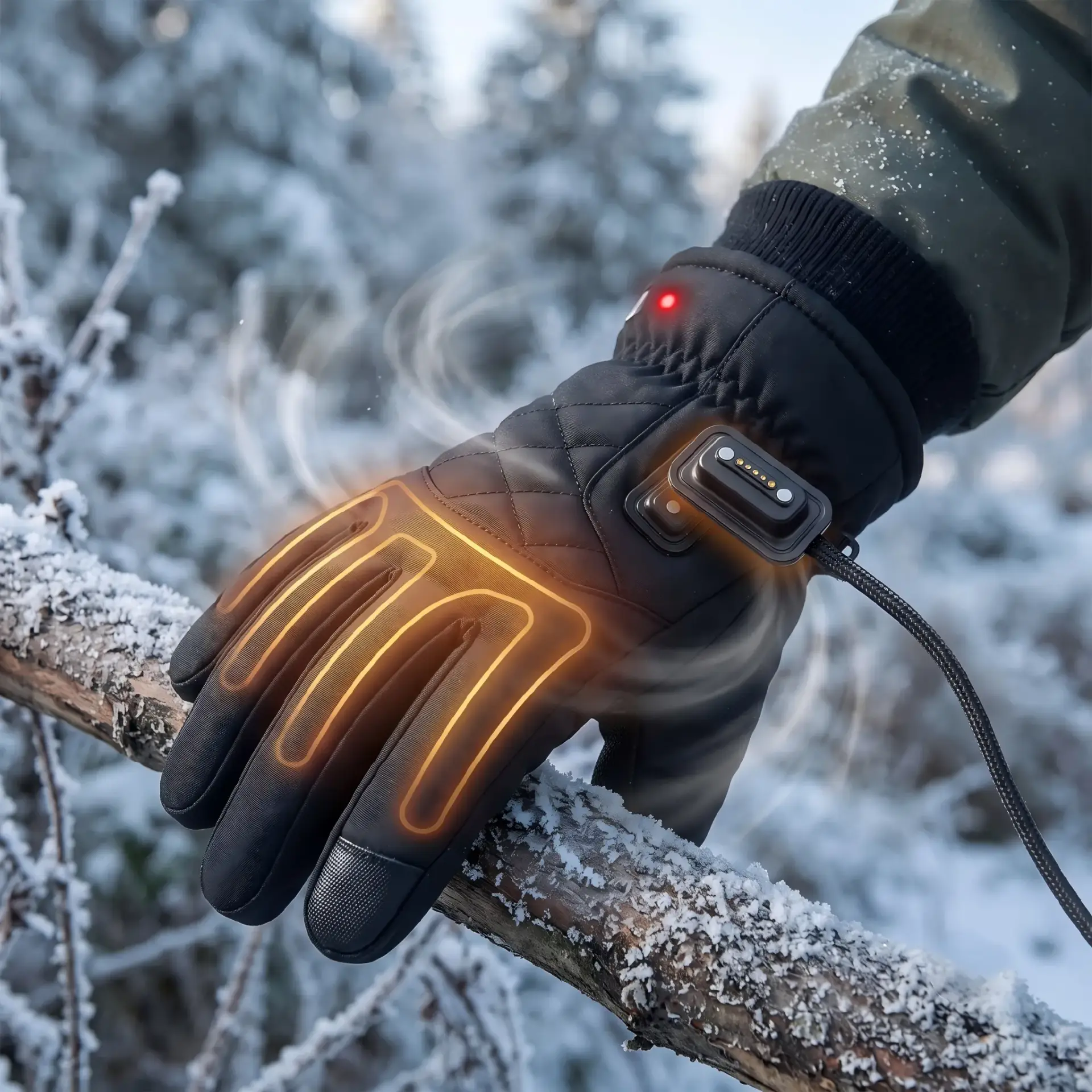
Heated Apparel Magnetic Connection
A detachable interface pattern for textile-integrated electronics where cable flexing, repeated disconnection, low-temperature use, garment movement and the washing process may influence the connector specification.
Read Smart Apparel Case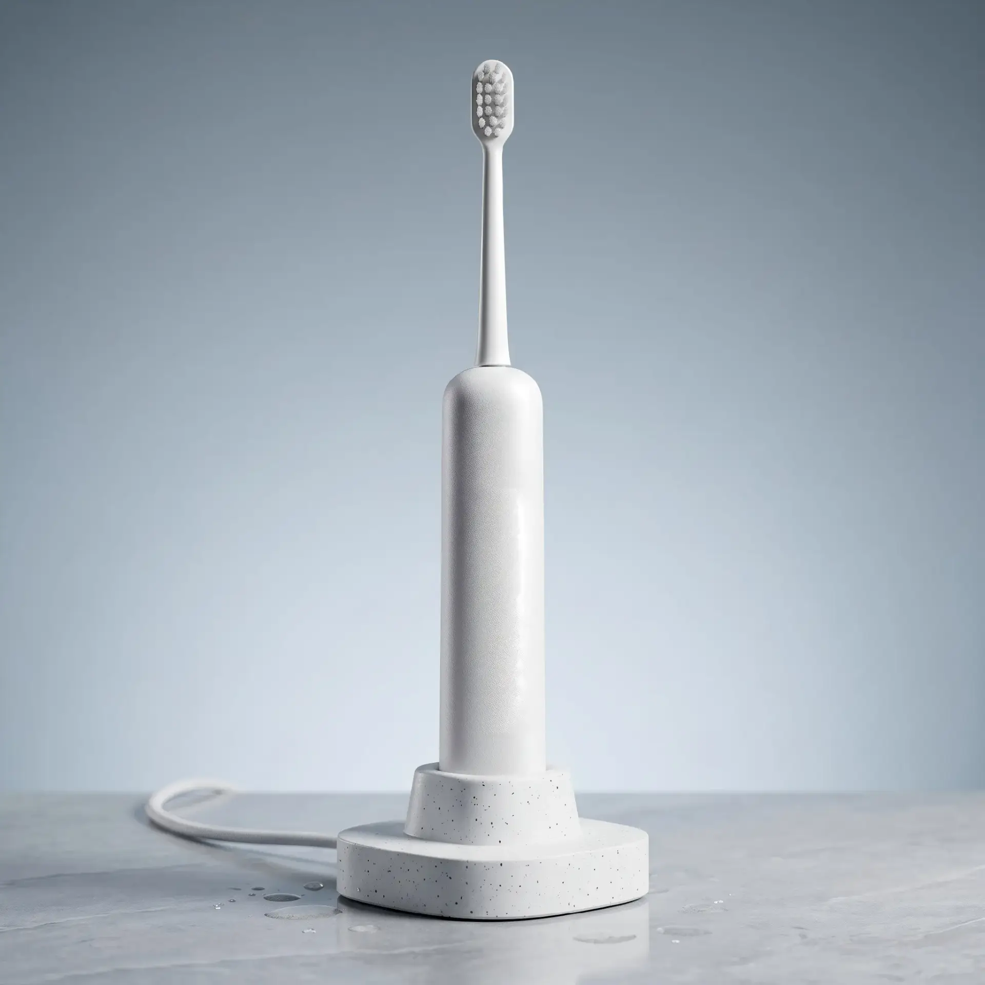
Electric Toothbrush Charging Base
A charging-base pattern for a device stored near water and cleaning residue, where surface geometry, drainage, contamination, charging alignment and the housing seal require device-level review.
Read Electric Toothbrush Case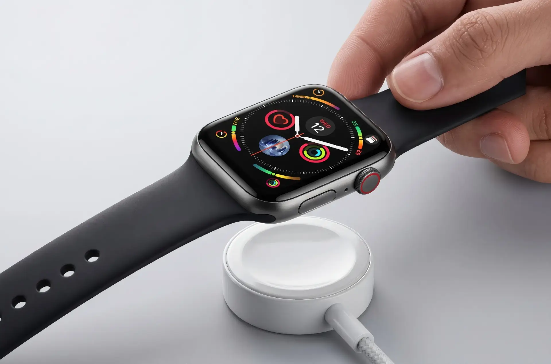
Smartwatch Magnetic Charger
A compact charging pattern for a body-worn device where charging temperature, sweat exposure, skin-contact surfaces, docking force and the thickness of the watch housing must be balanced.
Read Smartwatch Case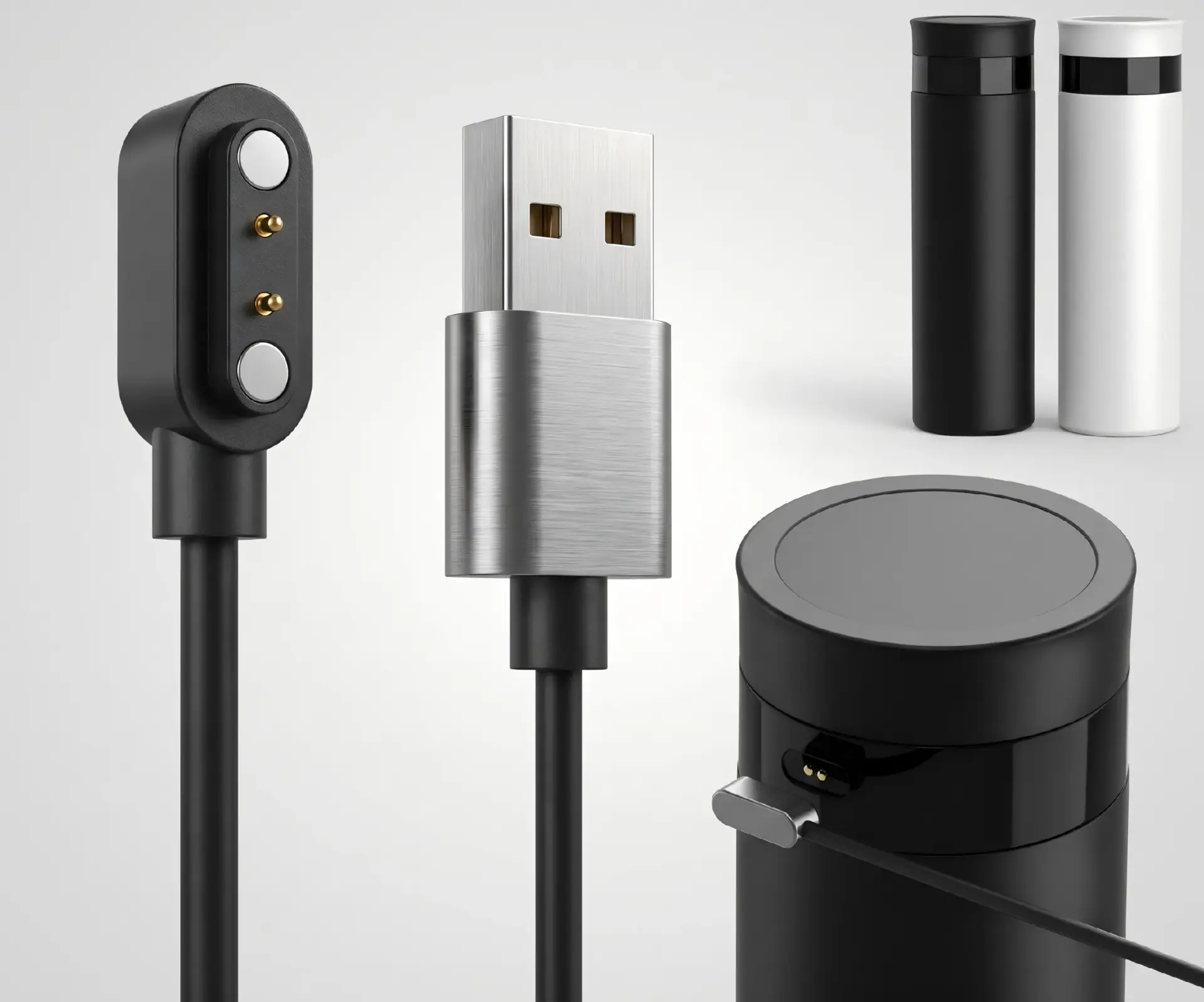
2-Pin Smart Water Bottle Charging Cable
A simple power-interface pattern for liquid-adjacent consumer products where a flat device contact, cable polarity, cleaning exposure and complete-housing sealing must be reviewed.
Read Smart Water Bottle Case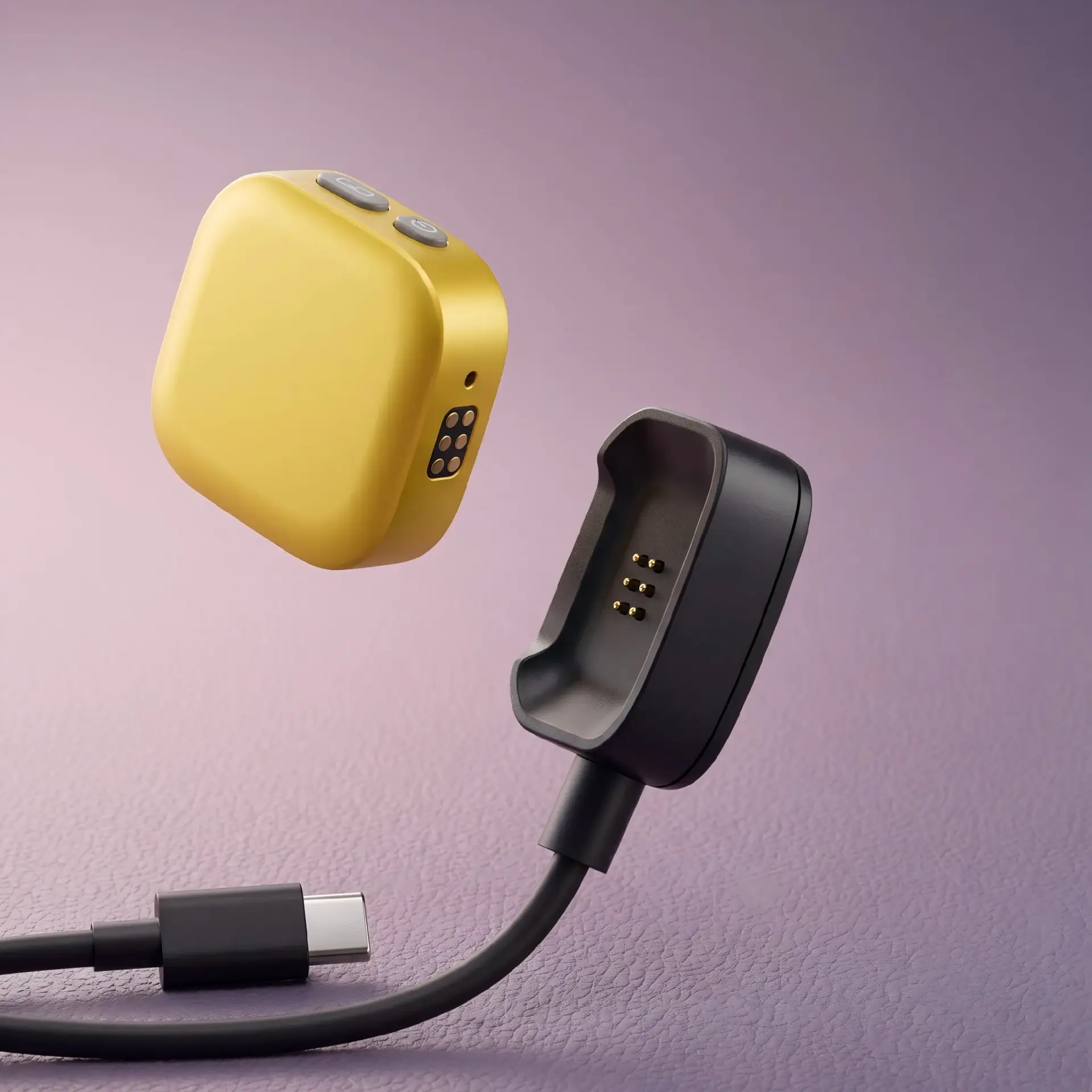
6-Pin Mini Microphone Cable
A higher-contact-count cable pattern for compact audio hardware where power, detection, control or selected data functions may share a small interface and require a documented pin map.
Read Mini Microphone Case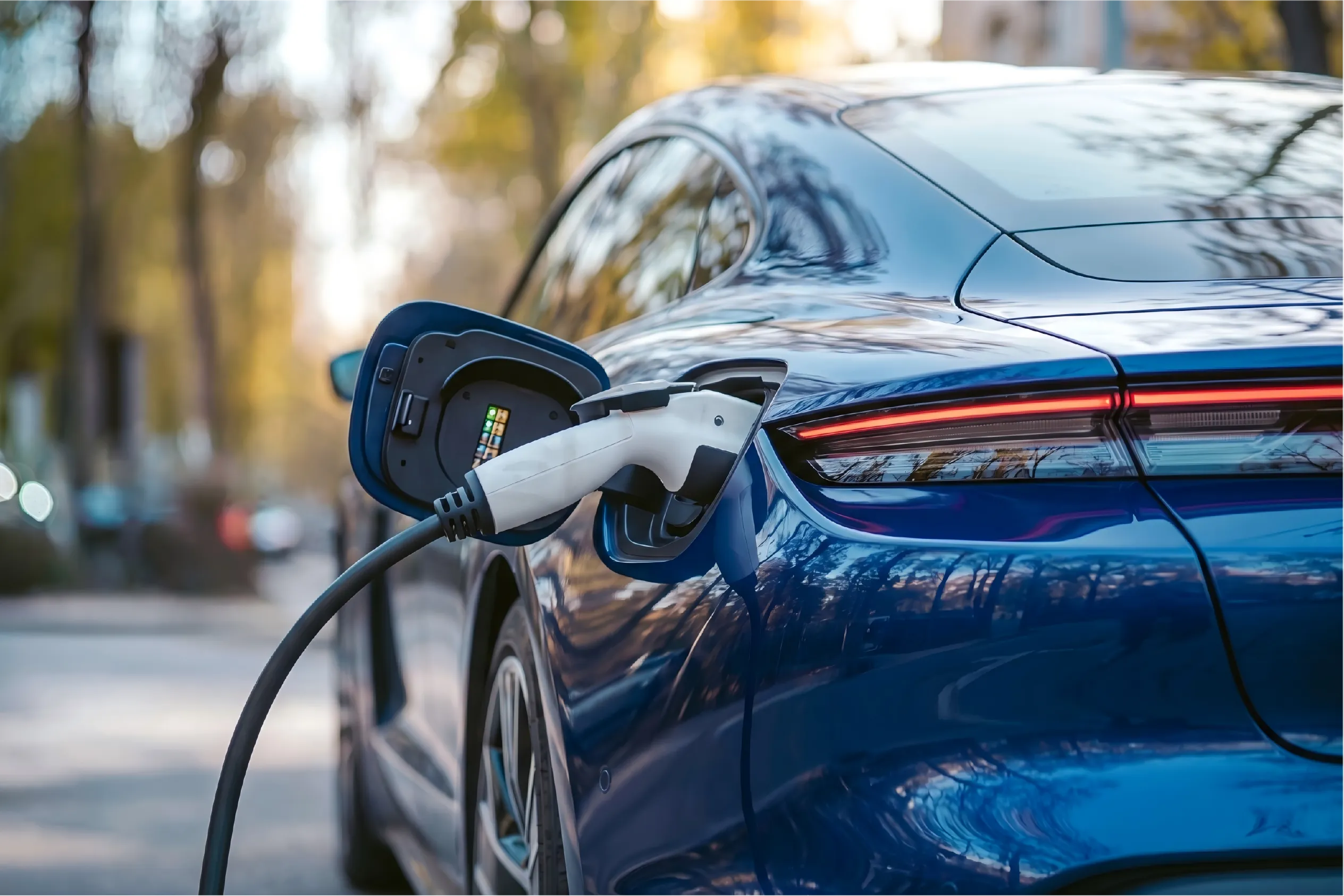
High-Current Mobility Charging Cable
A cable-architecture pattern for a higher electrical load where current distribution, conductor size, voltage drop, temperature rise, cable termination and mechanical protection must be evaluated as one system.
Read Mobility Charging CaseThe case images and summaries describe application patterns. They do not make every dimension, ingress rating, current value, material, magnet grade, data capability, test result or production outcome automatically applicable to a different customer project.
Start from the Engineering Constraint, Not Only the End Product
Two devices in different industries may share the same connector problem, while two products in the same industry may require completely different architectures.
Very Limited Connector Height
Start with cases involving thin or compact enclosures.
- AR smart glasses
- Smartwatches
- Mini microphones
Water, Sweat or Cleaning Exposure
Start with cases where the housing and connector seal must be reviewed together.
- Beauty devices
- Electric toothbrushes
- Smart water bottles
Body-Worn and User-Facing Docking
Start with cases where alignment, surface materials and release force affect the experience.
- AR glasses
- Smartwatches
- Heated apparel
Power Plus Detection, Control or Data
Start with a case that requires a documented multi-contact allocation.
- Mini microphones
- AR smart glasses
- Other multi-pin devices
Repeated Flexing or Pull Loads
Start with cases where cable outlet, strain relief and release direction are significant.
- Smart apparel
- Mobility charging cable
- Portable audio cable
Higher Current or Long Cable Path
Start with cases that treat contacts, conductor and cable length as one thermal path.
- Mobility charging cable
- Heated apparel
- Power-focused cable assemblies
Compare the Cases by Supply Scope and Primary Design Risk
Use the matrix to identify which case has the nearest engineering pattern. The final contact count and performance still depend on the new project requirements.
| Case pattern | Likely supply scope | Contact approach | Primary design risk | Key information needed |
|---|---|---|---|---|
| AR smart glasses | Connector or finished charging interface | Compact multi-contact layout | Z-height, sweat, docking UX | Temple section, pin map, PCB position, surface materials |
| Beauty device | Magnetic connector and device contact | Power-focused or low-contact-count interface | Cleaning chemicals and housing seal | Cleaning protocol, splash condition, housing and cable outlet |
| Heated apparel | Detachable connector or cable assembly | Power plus optional control contacts | Textile movement, flex and wash strategy | Current profile, garment routing, pull direction, washing method |
| Electric toothbrush | Charging base and device-side contacts | Low-contact-count charging interface | Bathroom contamination and drainage | Base geometry, water exposure, alignment and cleaning method |
| Smartwatch | Magnetic cable or charging dock | Compact charging and optional detection | Body-worn exposure and limited packaging | Current, housing thickness, contact location, magnetic force |
| Smart water bottle | 2-pin magnetic cable and device contact | Supply and return | Liquid exposure and washable surface | Voltage, current, polarity, cleaning and enclosure design |
| Mini microphone | Multi-pin finished cable assembly | Power plus additional channels | Signal definition and compact cable integration | Pin map, protocol, shielding, return paths and cable length |
| Mobility charging cable | Full cable and connector assembly | Current path sized for project load | Voltage drop, temperature rise and cable mechanics | Current profile, duty cycle, length, conductor and environment |
When Can an Existing Case Architecture Be Reused?
Reusing a connector is not a yes-or-no decision based on appearance. First compare the electrical interface, geometry, environment, cable scope and validation requirements.
Reuse is more realistic when these items match
- Electrical function: the contact allocation and current profile are substantially similar.
- Mechanical envelope: connector height, mating area, PCB/FPC location and compression range fit.
- Mating behavior: alignment, polarity, holding force and release direction suit the device.
- Environment: water, sweat, cleaning, temperature, vibration and contamination are comparable.
- Supply scope: the project needs the same component, cable, housing or termination boundary.
- Production process: assembly access, soldering, molding, inspection and packaging are compatible.
What a Strong Connector Case Study Should Show
A useful engineering case is more than a product image and a performance number. It should connect the original requirement to the selected design, verification method and production release.
Original Constraint
Document the device space, electrical interface, environment, UX and production target.
Selected Interface
Explain why a connector, finished cable, pogo pin array or individual contact was chosen.
Design Decisions
Show how pin count, force, cable, sealing, materials and mounting influenced one another.
Test Conditions
State sample configuration, test method, limit and whether testing was at component or device level.
Production Control
Freeze drawing, materials, critical dimensions, electrical checks and change-control requirements.
Move from a Comparable Case to the Correct Product or Solution Page
Questions About Using Connector Case Studies
Are these case studies standard products that can be ordered directly?
Not necessarily. Some cases may use an existing connector structure, while others may require a custom housing, cable, magnet arrangement, pin map or mounting method. Submit the new device requirements before assuming the exact case design can be reused.
Why are fixed performance numbers not shown on every case card?
A number is meaningful only with a defined assembly and test condition. Current, resistance, force, cycle life, corrosion and water protection can change with contact allocation, cable, housing, compression, materials and environment.
Can a 2-pin case be converted into a 4-pin or 6-pin version?
It may be possible, but adding contacts changes layout, spring reaction, magnetic-force requirements, insulation, PCB area and cable construction. The project should return to contact-budget and mechanical-envelope review.
Can the case image be treated as the final production drawing?
No. The image is an application or connector concept. Production requires an approved 2D drawing, material and plating specification, pin map, critical tolerances, magnetic direction, cable details and inspection criteria.
What should I send when asking for a similar design?
Send the case link, device application, pin map, current and voltage, available space, PCB/FPC position, cable requirements, magnetic-force target, operating environment, expected mating conditions, quantities and available STEP, IGES or 2D drawings.
How should a new project validate a reused case architecture?
Reconfirm fit, compression, continuity, voltage drop, temperature rise, magnetic holding and release force, cable pull, lifecycle and relevant environmental exposure on the new assembly. Component testing does not replace final-device validation.