
CTP / Application Engineering Reference
AR Smart Glasses Connector Engineering Example
An AR glasses interface is constrained by a narrow wearable enclosure, PCB placement and the way a user connects a cable or dock. Contact count, magnetic guidance and housing height must be reviewed together. The example is an engineering discussion pattern rather than a documented customer project.
Engineering reference only. No documented customer deployment, first-hand test report or approved application drawing is claimed on this page. Final custom values follow the agreed customer specification.
Start with the temple cross-section
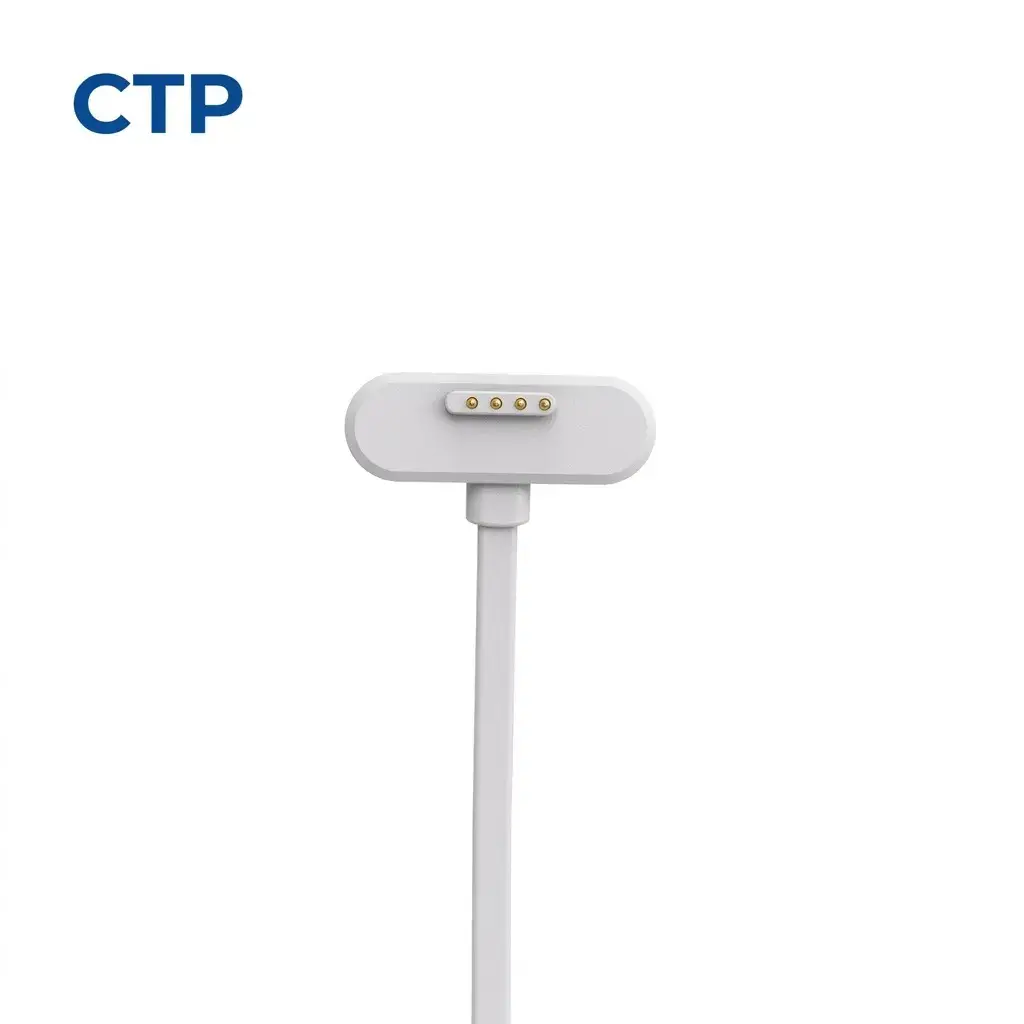
Provide the available connector height, wall thickness, PCB location, mating direction and cable clearance. Review tolerance and support for the device-side contact area. An existing linear contact arrangement can inform the discussion, but its geometry is not automatically suitable for a new glasses housing.
Define power and any signal functions
Document every contact and the intended electronics interface. If data is required, state the protocol and the complete cable and return-path requirements. Neither four contacts nor magnetic mating establishes high-speed performance; electrical suitability must be verified in the actual design.
Account for wearable handling
Identify sweat, cosmetics, cleaning and the intended skin-contact surfaces. Specify desired docking and release behavior and review the effect of cable movement near the temple. Magnet grade alone is not a guarantee of alignment or force. Device materials and any safety requirements need the appropriate evidence and sample acceptance.
Information to Send for Engineering Review
- Provide temple cross-section, PCB position and mating envelope.
- Send the complete power and signal pin map.
- Define cable routing, docking behavior and wearable exposure.
- Agree geometry, electrical function and mechanical sample checks.
Related Hardware and Next Steps
- View the pictured configuration — SKU CTP-MCC-4P-SR-A13
- Request a configuration review with this SKU reference
- Review compact connector assembly references
- Browse all application engineering examples
- Review company certificates and available engineering evidence
- Send your own project requirements
Email: bella@ytanpogo.com