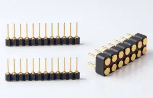
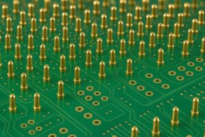
Waterproof magnetic pogo pin connectors should be designed from the
complete ingress-protection boundary rather than from a connector label
such as “IP68.” A flat contact interface can help simplify some enclosure
geometries, but final environmental performance depends on the pogo pin
feedthroughs, housing joints, seals, mating targets, PCB or cable
terminations and the condition in which the product is tested. Engineers
should separately evaluate the fully mated, partially mated and unmated
states, and should also define the electrical behavior of exposed contacts
when moisture is present.
What Does “Waterproof” Mean for a Magnetic Pogo Pin Interface?
The first design mistake is treating “waterproof magnetic pogo pin
connector” as one universal component category.
In practice, the engineering team should define exactly what requires
protection.The protected boundary may be:
- the pogo pin itself;
- the pogo pin feedthrough into the enclosure;
- the complete connector module;
- the connector-to-product housing joint;
- the PCB behind the connector;
- the entire finished device.
These are not the same sealing problem.

Therefore, the useful question is not:

“Is this pogo pin waterproof?”
It is:
    “What is the defined environmental boundary, and under which connector
    state must that boundary remain protected?”
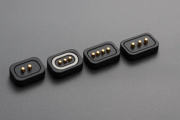
boundary rather than the visible contact surface alone.
Rule 1: Draw the Sealing Boundary Before Choosing the Seal
Waterproof connector development should begin with a cross-section of the
complete assembly.

On that section, engineers should identify every possible path from the
external environment to the protected electronics.
Potential ingress paths can include:
- around the pogo pin body;
- between the connector insert and housing;
- along a wire or cable exit;
- around an FPC transition;
- between the target pad and enclosure;
- around a fastener;
- through an adhesive interface;
- through another nearby enclosure opening.
A connector can have a well-sealed pogo pin feedthrough while the complete
device still leaks through another interface.
Seal the Actual Leak Path
Different construction methods can address different leakage paths.| Sealing Method | Possible Role | Engineering Variables |
|---|---|---|
| Insert Molding | Integrates contacts into an insulating structure | Material adhesion, molding geometry and process stability |
| Gasket / O-Ring | Seals a controlled mechanical joint | Compression, groove geometry, tolerance and material |
| Potting | Seals selected internal cavities or terminations | Adhesion, cure, voids, thermal expansion and repairability |
| Overmolding | Can protect cable or wire transition regions | Material compatibility and strain transfer |
| Housing Joint Seal | Protects the connector-to-product interface | Surface flatness, compression and assembly process |
These methods are complementary in some products, but they should not be
treated as interchangeable proof of an IP rating.
A Flush Contact Surface Can Simplify the Exterior — Not Eliminate Sealing
One reason engineers evaluate pogo pin interfaces is that the mating target
can sometimes be integrated into a relatively shallow external surface.

This can avoid the same type of deep insertion cavity used by some
plug-and-receptacle connectors.

However, behind the flush surface there is still a structural stack:


    External Surface
    →
    Contact / Target
    →
    Feedthrough
    →
    Housing Interface
    →
    PCB / FPC / Wire
    →
    Protected Electronics


Each transition should be included in the sealing review.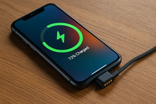
geometry, but feedthrough and housing sealing still require dedicated
design.
Magnets Are Not What Create the Waterproof Seal
Magnetic capture and environmental sealing should be treated as different
functions.

Magnets may help:- bring two connector halves together;
- provide seated retention;
- support a removable docking experience.
They do not automatically seal:- pogo pin feedthroughs;
- housing joints;
- wire exits;
- PCB interfaces;
- mating-target installations.
A non-magnetic pogo pin feedthrough can also be designed as part of an
ingress-protected enclosure.

Likewise, a very strong magnetic connection can still leak if the actual
sealing boundary is poorly designed.
Magnetic Force and Gasket Compression Should Not Be Confused
In some connector assemblies, the mating system may also compress a gasket.

In that case, the engineer should verify the actual mechanical load path.
A simplified load relationship can be considered as:
    Available Closing / Retention Force
    >
    Spring Reaction
    +
    Seal Compression Reaction
    +
    Expected Disturbance Loads


However, this does not mean that the magnets themselves define the gasket
compression.

Mechanical stops and controlled enclosure geometry should establish the
final compressed condition.
Why Mechanical Stops Matter
Without a controlled stop, increasing magnetic attraction can produce
excessive compression or inconsistent assembly load.

Depending on the structure, this can affect:- gasket compression;
- pogo pin working stroke;
- housing deformation;
- target position;
- removal force.
Therefore:


    Magnet force should retain the interface; mechanical geometry should
    define the final interface position.
Rule 2: Treat Mated, Partially Mated and Unmated States Separately
Waterproof-interface design often focuses only on the fully assembled
condition.

Magnetic removable connectors have several normal states that can require
separate analysis.| Interface State | Ingress Question | Electrical Question |
|---|---|---|
| Fully Mated | Is the intended environmental boundary complete? | Are all required contacts correctly seated? |
| Partially Mated | Can fluid reach an incompletely closed interface? | Can only some contacts become energized? |
| Unmated | Are the external targets directly exposed? | Are exposed conductive surfaces energized? |
| Wet After Separation | Can liquid remain on or around the interface? | What happens if the cable reconnects while wet? |
| After Cleaning | Can liquid become trapped around the seal? | Is electrical function restored before drying? |
The Unmated State May Be the Most Important State
A magnetic charging interface may spend most of its service life with the
cable or dock disconnected.

That means the device-side contacts can be directly exposed to:- rain droplets;
- condensation;
- sweat;
- cleaning fluid;
- dust;
- skin oils;
- foreign conductive objects.
Protecting the internal enclosure from water does not automatically solve
the electrical behavior of exposed wet contacts.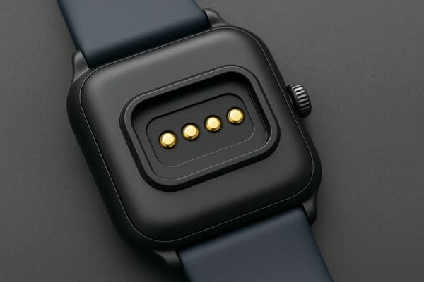
mated and unmated wet states rather than only in the sealed product
condition.
Water Ingress and Exposed-Contact Safety Are Different Problems
Consider a device whose enclosure remains closely sealed.

Water may still sit on the external conductive targets.

In that condition, the enclosure has not necessarily failed its ingress
requirement, but the electrical interface may still require analysis.
Potential issues can include:
- conductive bridging between contacts;
- electrochemical reactions;
- unexpected current paths;
- false connection detection;
- charging while contamination is present.
Do Not Assume Low Voltage Automatically Makes Wet Contacts Safe
Electrical behavior depends on the actual system voltage, current,
spacing, liquid composition, contact geometry and power architecture.

The product should therefore define what happens electrically when the
connector is exposed.
Connection Detection Can Be Separated from Power Enable
A magnetic cable begins to attract before every electrical contact has
necessarily reached its final working position.

For applications where wet or partial connection creates meaningful risk,
the electrical sequence can be designed separately from magnetic attachment.
A possible sequence is:
    Cable Approaches
    →
    Magnetic Capture
    →
    Mechanical Seating
    →
    Required Contacts Engage
    →
    Connection State Validated
    →
    Main Power Enabled


This does not mean every magnetic connector requires complex electronics.

It means power-state behavior should be deliberately defined instead of
assumed.
Rule 3: Design for Water Removal, Not Only Water Exclusion
Complete prevention of external wetting is not realistic for every
application.

In many portable, outdoor and industrial interfaces, the external connector
surface will eventually become wet.

The product should therefore consider how liquid leaves the interface.
Drainage Geometry Can Be Part of Connector Reliability
Design questions can include:
- Can liquid pool around the contacts?
- Does the connector create a closed pocket?
- Can gravity remove liquid in the normal product orientation?
- Can trapped liquid remain beneath the magnetic cable head?
- Can dirt block the drainage path?
- Is the interface easy to wipe or inspect?
A flat surface can improve accessibility, but completely flat geometry can
also allow a thin liquid film to remain between mating surfaces.

Therefore the engineering goal is not automatically:

“Make everything closely flat.”
It is:
“Control how liquid enters, where it can remain and how it can leave.”
Capillary Paths Often Exist at Small Mechanical Gaps
Small gaps around components can provide liquid migration paths even when
the opening is visually difficult to see.

Engineers should pay attention to interfaces such as:- metal-to-polymer boundaries;
- insert-molded contact edges;
- adhesive joints;
- housing seams;
- wire or FPC exits;
- fastener regions.
The actual leak path should be identified by section analysis and validation
rather than inferred only from the exterior appearance.
Contamination Changes the Wet-State Problem
Pure-water laboratory exposure and field contamination are not always the
same electrical environment.

Depending on the application, the connector may encounter mixtures
containing:- salts;
- sweat;
- dust;
- oil;
- cleaning agents;
- industrial process fluids.
Water ingress protection should therefore not automatically be used as proof
of corrosion resistance or chemical compatibility.
Self-Wiping Does Not Mean Self-Cleaning
Limited contact movement may disturb some surface film.

It does not ensure removal of:- salts;
- sticky residue;
- oil;
- abrasive particles;
- corrosion products;
- metallic debris.
Magnets Create an Additional Debris Consideration
Ferromagnetic particles can accumulate near the mating surface of a
magnetic connector.
They can potentially:
- block complete seating;
- change pogo pin working stroke;
- scratch contact surfaces;
- bridge adjacent conductive regions;
- retain moisture around the contact interface.
Outdoor and industrial validation should therefore consider realistic
contamination where relevant.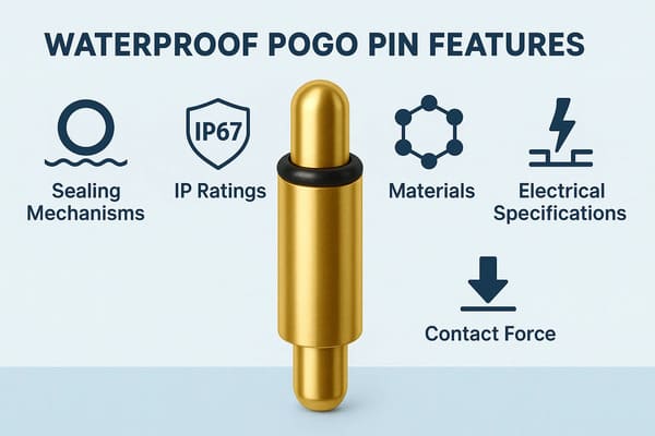
contamination, contact exposure and the complete product enclosure.
Rule 4: Treat the IP Test as Qualification of a Defined Configuration
An ingress-protection result should be associated with the exact
configuration that was tested.

Before qualification, engineers should define:- connector model and revision;
- complete enclosure configuration;
- mated or unmated state;
- gasket or seal configuration;
- assembly torque where applicable;
- cable or termination condition;
- sample preconditioning;
- acceptance criteria;
- post-test inspection method.
IEC 60529 defines degrees of protection provided by electrical-equipment
enclosures through the IP Code. For automotive electrical equipment,
ISO 20653 provides a road-vehicle-specific IP-code framework.

The applicable standard and test configuration should be selected from the
actual product and industry requirements rather than from the connector
appearance alone.
Do Not Turn IP67, IP68 and High-Pressure Water Tests into a Simple Ladder
Product teams sometimes treat ingress ratings as if the only engineering
goal were to select the largest number.

A better approach is to begin with the real exposure condition.| Exposure Question | Engineering Input |
|---|---|
| Dust Exposure | What particles and enclosure state are expected? |
| Rain / Splash | Direction, duration and product orientation |
| Immersion | Required product condition, depth / pressure and duration |
| Pressurized Cleaning | Actual cleaning process and applicable industry requirement |
| Wet Unmated Interface | Electrical state of accessible contacts |
The qualification target should follow the product environment, not a
marketing hierarchy.
IP68 Is Not the Same as Hermetic Sealing
These terms should not be used interchangeably.

An IP rating describes protection provided by an enclosure under the
applicable test framework.

“Hermetic” has a different technical meaning and should not be used simply
because an assembly passed an ingress test.

Therefore marketing language such as:

“IP68 hermetically sealed pogo pin”

should only be used when both claims are independently supported by the
applicable specification and test method.
Passing an IP Test Does Not Finish the Connector Qualification
For an electrical interface, the engineering team may also need to confirm
whether environmental exposure changed the functional performance of the
connector.
Post-test checks can include:
- visual evidence of water ingress;
- contact resistance;
- voltage drop;
- temperature rise under load;
- pogo pin movement;
- working stroke;
- seal condition;
- housing deformation;
- corrosion or residue;
- magnetic retention where relevant.
Why Post-Exposure Electrical Testing Matters
A connector may avoid visible leakage into the electronics while its
external contact system still changes after exposure.

For example:- residue can increase interface resistance;
- corrosion can develop after the wet test;
- contamination can prevent complete seating;
- a seal can deform after repeated assembly;
- a wet interface can behave differently under load.
Therefore, ingress protection and electrical durability should be treated as
related but separate validation questions.
Waterproof Does Not Mean Saltwater Resistant
Passing a water-ingress test should not automatically be interpreted as
proof of long-term operation in seawater or salt-containing environments.

Salt exposure introduces additional corrosion and residue mechanisms.

Where salt is relevant, the engineering plan should separately define:- actual salt exposure;
- mated / unmated state;
- electrical condition;
- cleaning after exposure;
- corrosion acceptance criteria;
- post-test electrical performance.
Waterproof Does Not Mean Sweat Resistant
Wearable devices create another example.

Sweat is not simply water.

Long-term interface behavior can depend on:- salt content;
- skin oils;
- drying residue;
- repeated wet / dry cycles;
- contact cleaning;
- electrical state during exposure.
Sweat resistance should therefore be validated independently when it is a
real product requirement.
Waterproof Does Not Mean Chemical Resistant
Industrial or medical equipment may encounter cleaning agents, oils,
coolants or other process fluids.

A seal or polymer that performs well in water can respond differently to
another fluid.

Chemical compatibility should therefore be evaluated using the actual
application-relevant substances.
Repeated Opening Can Change the Seal
If the environmental boundary relies on a mating gasket, repeated
connection can introduce another lifecycle dimension.
Engineers may need to evaluate:
- compression set;
- surface wear;
- contamination on the sealing face;
- gasket displacement;
- housing tolerance change;
- retention-force change.
A seal that passes when new should not automatically be assumed to perform
identically after the complete mating lifecycle.
Waterproof Magnetic Connector Failure-Mode Map
| Observed Problem | Possible Root Cause | Engineering Check |
|---|---|---|
| Water Behind Connector | Feedthrough or housing leakage | Section sealing boundary |
| Water Between Mating Halves | External surface exposure | Drainage and electrical wet-state design |
| Intermittent Charging When Wet | Contamination or partial mating | Connection detection and contact condition |
| Corrosion After Testing | Residual fluid or material compatibility | Post-exposure inspection and materials review |
| Seal Passes Initially but Later Leaks | Compression set or assembly variation | Lifecycle plus sealing test |
| Connector Cannot Fully Seat | Debris or seal interference | Contamination and tolerance testing |
| Only Some Contacts Engage | Partial mate or uneven working stroke | Mechanical datum and state detection |
Recommended Waterproof Connector Validation Sequence
A useful qualification workflow is:


    Define Exposure
    →
    Draw Sealing Boundary
    →
    Define Mated / Unmated States
    →
    Build Mechanical Tolerance Stack
    →
    Establish Electrical Wet-State Behavior
    →
    Baseline Measurement
    →
    Ingress Test
    →
    Post-Test Electrical Inspection
    →
    Lifecycle Exposure
    →
    Repeat Ingress Validation
Waterproof Magnetic Pogo Pin Validation Matrix
| Validation Area | Recommended Engineering Check |
|---|---|
| Sealing Boundary | Identify every path between environment and protected electronics |
| Feedthrough | Verify sealing around pogo pins and inserts |
| Housing Joint | Evaluate surface flatness, seal compression and assembly variation |
| Mated State | Evaluate environmental and electrical performance while fully seated |
| Partial Mate | Evaluate exposed and early-engaging contacts |
| Unmated State | Evaluate exposed targets and power state |
| Drainage | Check pooling and trapped fluid in normal orientations |
| Contamination | Evaluate representative dust, residue and metallic debris |
| Ingress Test | Use the applicable product configuration and standard |
| Post-Test Electrical | Measure contact resistance, voltage drop or temperature where required |
| Lifecycle | Repeat exposure after representative mating and seal aging |
| Materials | Separately evaluate salt, sweat and chemical compatibility where relevant |
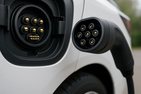
installation, sealing boundary and use state rather than from a generic
automotive or industrial label.
Information Required for a Waterproof Magnetic Connector Review
| Project Input | Information to Provide |
|---|---|
| Application | Wearable, industrial, outdoor, medical, automotive or another device |
| Required Protection | Applicable customer or product ingress requirement |
| Protected Boundary | Connector, enclosure, electronics cavity or complete product |
| Mated Requirement | Required environmental behavior while connected |
| Unmated Requirement | Required behavior while contacts are exposed |
| Mechanical Geometry | X-Y-Z space, mating direction and mechanical datums |
| Working Stroke | Minimum, nominal and maximum pogo pin compression |
| Seal Architecture | Gasket, insert molding, potting or other planned boundary |
| Electrical Conditions | Voltage, continuous current and peak current |
| Power State | Electrical behavior when connected, disconnected and wet |
| Fluids | Water, sweat, salt, cleaners, oil or project-specific chemicals |
| Cleaning | Cleaning method and expected cycle count |
| Lifecycle | Expected mating cycles and environmental aging |
| Project Files | 2D section, 3D assembly, PCB layout and enclosure model |
Frequently Asked Questions
What is a waterproof magnetic pogo pin connector?
It is a magnetic spring-contact interface designed as part of an assembly
with defined protection against environmental ingress. The actual protection
level depends on the complete connector and enclosure configuration and its
validation.
Are magnetic pogo pin connectors automatically IP68?
No. IP performance belongs to a defined and tested enclosure or assembly.
Magnetic attachment, a flat contact surface or a visible gasket does not by
itself establish an IP rating.
Do magnets create the waterproof seal?
Not necessarily. Magnets primarily provide capture and retention. The
environmental boundary is normally created by feedthrough design, housing
geometry, seals, molding, potting or other defined structural features.
Do stronger magnets improve waterproof performance?
Not automatically. If the mating system compresses a seal, adequate closing
force is required, but the final gasket and pogo pin compression should be
controlled by the mechanical design rather than magnet strength alone.
Is a flat pogo pin interface easier to waterproof than USB?
A shallow contact surface can simplify certain enclosure architectures,
but the complete feedthrough, housing and product boundary still require
sealing and testing. It is not universally more waterproof.
Is IP68 the same as hermetic sealing?
No. An IP rating and hermeticity are different technical concepts and should
not be used interchangeably without supporting specifications and tests.
Does waterproof mean saltwater resistant?
No. Salt exposure introduces additional corrosion and residue mechanisms
that should be evaluated separately when relevant.
Does waterproof mean sweat resistant?
No. Sweat can leave salts and other residue on exposed contacts. Wearable
interfaces should be validated for their real sweat and cleaning conditions.
What happens if a magnetic charging connector is wet while disconnected?
The enclosure may remain protected while the external contacts are still
wet. The electrical system should therefore define exposed-contact power
state, reconnection behavior and contamination handling.
Should an IP test be performed with the connector mated or unmated?
The tested configuration should follow the actual product requirement.
If both states matter in use, they may require separate engineering
evaluation.
Should electrical performance be checked after waterproof testing?
Yes when electrical interface performance is part of the product
requirement. Post-test checks can identify resistance drift, corrosion,
seal damage, incomplete movement or other degradation.
Can insert molding supports IP68?
No. Insert molding can contribute to the sealing architecture, but final
ingress protection depends on the complete assembly and defined test
configuration.
What information is needed to customize a waterproof magnetic pogo pin connector?
Provide the required environmental condition, complete enclosure geometry,
mated and unmated requirements, Pin Map, voltage, current, working stroke,
sealing concept, relevant fluids, lifecycle and 2D or 3D product files.
Request a Waterproof Magnetic Connector Engineering Review
Explore

    custom magnetic connector solutions

for removable charging, docking and environmentally exposed interfaces.

Review

    pogo pin and spring-contact solutions

for project-specific electrical contact structures.

Learn more about CTP engineering and manufacturing capabilities on the

    About Us page
.

Submit your enclosure section, sealing requirement, Pin Map, voltage,
current, working stroke, environmental exposure and product drawings through
the

    Get Quote & Samples page
.


    CTP can review pogo pin feedthroughs, connector housing geometry,
    working stroke, mating targets, magnetic capture, sealing structures and
    PCB, FPC, wire or cable termination for custom waterproof magnetic
    connector projects. Final IP performance, corrosion resistance,
    chemical compatibility, electrical wet-state behavior and lifecycle
    depend on the approved product configuration and project-specific
    validation.
CTP ENGINEERING PATHS
Choose the right path for your project
Move from application requirements to a connector pair, a data-capable cable assembly, or a charging cable configuration. Final specifications are confirmed against an approved drawing and project validation plan.
Magnetic Connectors
Connector geometry, pin layout, mechanical integration and OEM/ODM review.
Engineering overview → 02Magnetic Data Cables
Power and signal allocation, cable exit, interface selection and assembly review.
Cable engineering → 03Magnetic Charging Cables
Browse the complete cable catalog and shortlist a starting structure for customization.
View cable catalog →