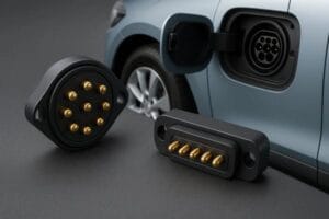
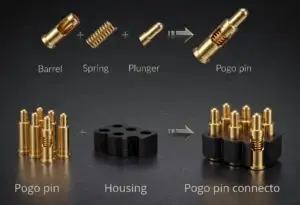
A magnetic connector is not electrically valid simply because the two halves attract each other. A reliable interface must move through several controlled states: magnetic capture, mechanical guidance, final seating, pogo pin compression, stable electrical contact, and controlled separation.
This distinction matters because the magnet, housing, spring-loaded contacts, mating targets, and system electronics perform different jobs. If those jobs are not separated during design, a connector can appear to mate correctly while the contacts are under-compressed, offset, partially energized, or mechanically overloaded.
This article focuses on contact-based magnetic connectors that use spring-loaded contacts or defined conductive mating surfaces. It does not describe inductive wireless charging.
What Does a Magnetic Connector Actually Do?
A magnetic connector is an electromechanical interface in which magnetic attraction assists the connection or retention of two mating parts while conductive contacts transfer power, ground, signals, detection circuits, or other electrical functions.
The important engineering point is that the complete connector performs several separate functions.
| Interface Function | Primary Design Element | Engineering Responsibility |
|---|---|---|
| Initial capture | Magnetic system | Attract the two halves when they enter the intended capture region |
| Final alignment | Housing, guides, keys, datums | Control lateral position, angle, orientation, and final seating geometry |
| Contact compliance | Pogo pins or other compliant contacts | Maintain local contact force across the approved compression range |
| Final Z position | Mechanical stops and product stack-up | Define the installed compression of the spring-loaded contacts |
| Electrical transfer | Contacts, mating targets, PCB, cable, and terminations | Carry the required electrical functions through the complete path |
| Connection-state control | System electronics, where required | Detect, identify, validate, current-limit, or enable power according to the system architecture |
This leads to a fundamental design rule:
Magnetic capture is not the same as mechanical seating, and mechanical seating is not automatically the same as a valid electrical connection.
The Mating Sequence: From Approach to Valid Connection
The easiest way to understand magnetic connectors is to treat mating as a sequence of states rather than one single event.
1. Approach
The two mating halves begin outside the effective capture region. Their relative position may be controlled by a user, cable, dock, fixture, product enclosure, robotic mechanism, or removable module.
At this stage, the important variables are not only distance. Approach angle, lateral offset, connector orientation, cable load, and the surrounding mechanical geometry can all influence what happens when magnetic attraction begins.
2. Magnetic Capture
As the air gap becomes smaller, magnetic attraction begins pulling the mating halves toward one another.
This stage should provide enough capture behavior for the intended use case, but the magnet should not be expected to correct unlimited positional error.
The effective behavior depends on the assembled magnetic system, including magnet location, polarity arrangement, return structure, air gap, housing geometry, and the direction from which the two halves approach.
3. Mechanical Guidance
Once the connector enters the final mating region, mechanical geometry should increasingly control position.
Possible locating features include:
- recesses and mating pockets;
- keys and asymmetric housing geometry;
- locating bosses;
- guide surfaces;
- mechanical shoulders;
- defined enclosure datums.
The magnet may help bring the parts together, but the mechanical design should establish the final position where electrical consequences depend on precise contact alignment.
4. First Electrical Contact
The pogo pin tips or mating contacts eventually touch their target surfaces.
First touch does not necessarily mean that the connector has reached its intended operating position.
At first contact, the spring-loaded pins may have little compression. Contact resistance and contact stability can also change as the connector continues moving toward the mechanical stop.
5. Pogo Pin Compression and Final Seating
As mating continues, the spring-loaded contacts compress.
The final installed compression should be determined by the complete product stack-up rather than by total pogo pin travel alone.
The stack-up can include the pogo pin free height, connector mounting position, PCB position, target height, housing dimensions, enclosure tolerances, seal compression, mechanical-stop position, and structural deflection.
The mechanical stop or final datum should establish the seated geometry. The pogo pins should provide compliant electrical contact, not act as the structural stop for the complete connector assembly.
6. Valid Electrical State
A connector may be physically seated before the system treats it as electrically valid.
Depending on the application, the system may need to confirm one or more conditions before enabling the final electrical function:
- continuity;
- correct accessory identification;
- acceptable orientation;
- presence of ground or return contact;
- stable connection detection;
- correct power sequence;
- absence of an obvious fault state.
Whether these functions are required is project-specific. The important principle is that system-level validation should not be replaced by an assumption that magnetic attraction supports correct electrical mating.
7. Controlled Separation
Removal is another engineering state rather than simply the reverse of connection.
The required behavior can be different for axial pull, cable peel, lateral sliding, rotation, or an off-axis load.
A magnetic connector designed for intentional breakaway should therefore be reviewed in the actual separation direction expected in the product.
Magnetic Capture Is Not the Same as Mechanical Seating
A common design error is to ask the magnetic system to perform too many functions.
Magnets are useful for attraction and retention. They may also influence orientation when polarity and geometry are intentionally arranged.
However, magnets alone should not be treated as precision mechanical datums.
Consider a connector that approaches with lateral offset. Magnetic attraction may pull the two halves together, but the final position can still be incorrect if the housing does not provide sufficient guidance.
The result may be:
Lateral offset → incomplete seating → incorrect pogo pin compression → unstable contact condition.
A second possible chain is:
Angular error → one side touches first → uneven pogo compression → tilted seating → contact or housing overload.
These are mechanical problems even though the connector may appear to have successfully “snapped” together.
The design target should therefore be:
Magnetic capture → mechanical location → controlled contact compression.
Each stage should have a defined engineering responsibility.
How Magnetic and Spring Forces Interact
Once spring-loaded contacts begin compressing, they create a reaction force that opposes further closure.
This means the magnetic system does not operate independently from the pogo pins.
A useful simplified engineering model is:
Available seated retention ≈ magnetic attraction − spring reaction − other separating loads.
This is a design bookkeeping model rather than a universal magnetic-force equation. Actual magnetic attraction changes with geometry, air gap, offset, material, and the complete magnetic circuit.
Other opposing loads may include seal compression, cable load, housing deformation, or externally applied forces.
This creates a real trade-off.
Increasing magnetic retention may improve holding margin, but it can also increase:
- user removal force;
- closing impact;
- housing load;
- peel resistance;
- attraction of ferromagnetic debris;
- the consequences of incorrect mating geometry.
Therefore:
Stronger magnet does not automatically mean better connector.
The required magnetic behavior should be defined from the application, including capture, seated retention, and intended release direction.
Why the Mechanical Datum Controls Pogo Pin Working Stroke
Working stroke is the compression range in which a spring-loaded contact is intended to operate after the complete product is assembled.
It should not be confused with total available travel.
The connector designer should evaluate at least three assembled conditions:
- minimum compression;
- nominal compression;
- maximum compression.
These conditions come from the complete tolerance stack.
For example:
Connector mounting height → enclosure datum → target position → mechanical stop → final pogo compression.
If the stack-up allows too little compression, contact force and stability may be insufficient.
If it allows excessive compression, the contact, housing, PCB, or target surface may experience unnecessary mechanical load.
The design objective is not maximum compression. It is a controlled operating window across all approved assembly conditions.
When Does the Electrical Connection Become Valid?
Electrical continuity can begin before the connector reaches its final seated condition.
This creates an important system-design question:
Should the system become electrically active at first contact, or only after the connection has been validated?
The correct answer depends on the project.
For a simple low-risk circuit, no sophisticated mating-state logic may be necessary. Other systems may use dedicated contacts, detection circuitry, current limiting, identification, sequencing, or controller logic.
The electrical path should also be evaluated as a complete system.
A simplified path may be represented as:
Source → PCB or cable → termination → pogo contact → mating interface → target → PCB or cable → load
The complete path resistance contributes to voltage drop and power loss:
Vdrop = I × Rpath
Ploss = I² × Rpath
This is why current capability should not be inferred from one pogo pin specification alone. Contact condition, working stroke, termination, cable, PCB routing, ambient condition, and duty cycle may all influence the finished interface.
How Tolerance and Misalignment Create Partial-Mating Failures
Magnetic connectors are often selected because the mating action can tolerate more user variation than a rigid plug-in interface.
That does not mean dimensional tolerance disappears.
The interface still has to control:
- lateral offset;
- angular error;
- rotation;
- Z-height variation;
- housing flatness;
- target position;
- mechanical-stop tolerance;
- PCB or enclosure deflection.
One important failure chain is:
Tolerance stack error → reduced installed stroke → lower contact condition margin → higher sensitivity to vibration or contamination.
Another is:
Excessive compression → increased spring reaction → reduced net retention margin → greater structural load.
The magnet cannot automatically compensate for these conditions because the problem occurs at the final mechanical interface.
Common Magnetic Connector Failure Modes
| Failure Condition | Possible Mechanism | Engineering Check |
|---|---|---|
| Weak capture | Insufficient magnetic attraction at the actual approach geometry | Evaluate capture behavior with assembled housing and expected offset |
| Magnetically attached but not seated | Housing interference, debris, offset, or poor datum control | Measure final seating position and working stroke |
| Under-compression | Tolerance stack leaves insufficient pogo pin stroke | Calculate minimum installed compression |
| Over-compression | Mechanical stop or stack-up drives excessive stroke | Calculate maximum installed compression and structural load |
| Intermittent contact | Movement, contamination, low compression, wear, or unstable seating | Monitor continuity or resistance under representative disturbance |
| Incorrect contact during partial mating | Offset allows unintended pad-to-pin contact | Review every credible mating position and Pin Map |
| Excessive removal force | Retention is too high for the actual separation direction | Measure axial, peel, sliding, or other relevant release behavior |
| Metallic contamination | Ferromagnetic particles collect around the magnetic interface | Evaluate the real operating environment and cleaning strategy |
Failure analysis becomes more useful when it is tied to a state transition rather than described only as a generic connector defect.
For example:
Contamination → incomplete seating → reduced working stroke → unstable resistance → voltage drop or functional interruption.
How to Validate a Magnetic Connector Interface
Validation should demonstrate that the complete mating sequence works under defined product conditions.
| Requirement | Test Condition | Measurement | Post-Test Check |
|---|---|---|---|
| Reliable capture | Defined approach positions and offsets | Capture behavior and successful mating | Inspect seating consistency |
| Correct seating | Minimum, nominal, and maximum tolerance conditions | Final position and pogo compression | Check for interference or damage |
| Controlled separation | Application-specific pull direction | Engaging or separating force | Inspect housing, magnets, and contacts |
| Stable electrical contact | Fully seated interface | Contact or path resistance | Repeat measurement after mechanical tests |
| Dynamic stability | Representative motion, cable load, or vibration | Continuity or resistance variation | Inspect contact surfaces |
| Lifecycle performance | Project-defined mating duty | Electrical and mechanical drift | Compare against project acceptance criteria |
IEC 60512 provides standardized connector test methods that can support a project-specific validation plan. For example, IEC 60512-13-1 addresses engaging and separating forces, IEC 60512-2-2 addresses contact resistance measurement, and IEC 60512-9-1 and IEC 60512-9-3 address mechanical operating endurance under defined conditions.
The standard test method does not replace the project specification. The actual sample configuration, operating state, severity, and acceptance criteria still need to be defined for the application.
Waterproofing Is a Separate Engineering Question
A magnetic connector may be integrated into a sealed device surface, but magnetic mating itself does not establish an ingress-protection rating.
The sealing system may involve connector inserts, enclosure interfaces, gaskets, adhesive, potting, molding, cable entry, drainage, or other project-specific structures.
IEC 60529 classifies degrees of protection provided by enclosures. Therefore, an IP claim should refer to a defined and tested assembly and mating condition rather than being inferred from the presence of magnets, flat contacts, or a visible seal.
When a Magnetic Connector May Not Be the Right Architecture
A magnetic interface is useful when removable mating, low insertion effort, controlled breakaway, docking, or spring compliance creates real product value.
Another connector architecture may be more appropriate when:
- a positive mechanical lock must remain engaged under substantial external load;
- standardized third-party cable interoperability is a primary requirement;
- an established high-speed connector already satisfies the electrical and mechanical requirement;
- the interface operates in an environment with uncontrolled ferromagnetic contamination;
- the connection is permanent and magnetic capture adds little value;
- the product cannot adequately control exposed electrical states;
- the available architecture cannot provide reliable mechanical guidance or final seating.
The correct question is therefore not:
“Are magnetic connectors better?”
It is:
“Does magnetic capture solve a real interface problem while the mechanical and electrical architecture can control the resulting trade-offs?”
Inputs to Define Before Engineering Review
Before developing a custom magnetic connector, define the mating system rather than only requesting a pin count and magnetic force.
Useful project inputs include:
- what the connector connects;
- approach and removal directions;
- available X, Y, and Z space;
- mechanical datum and stop concept;
- expected lateral and angular mating tolerance;
- required Pin Map;
- voltage, current, and duty condition;
- PCB, FPC, wire, or cable architecture;
- expected environmental exposure;
- required capture, retention, or breakaway behavior;
- expected mating duty;
- 2D or 3D product drawings where available.
Engineers evaluating available structures can review CTP’s magnetic connector category and the spring-loaded magnetic connector architecture guide. Projects that have moved from architecture discussion to component selection can continue with the magnetic pogo pin connector selection guide.
Frequently Asked Questions
What is a magnetic connector?
A magnetic connector is an electrical interface in which magnets assist capture or retention while conductive contacts transfer electrical functions. The housing, mechanical guides, contacts, mating targets, and system electronics may all contribute to the finished connection.
Do magnets carry the electrical current?
Normally, no. In the magnetic pogo pin architecture discussed here, the magnetic system performs a mechanical capture or retention function while dedicated conductive contacts carry power or signals.
Do magnets provide the pogo pin contact force?
Not directly. The compressed pogo pin spring provides local contact force against the mating target. Magnetic attraction helps close and retain the complete interface, so the two force systems must be evaluated together.
Does magnetic attraction supports correct alignment?
No. Magnetic attraction can assist capture, but mechanical guides, datums, keys, and stops should control the final position where precise contact alignment is required.
Is stronger magnetic force always better?
No. More retention may increase holding margin, but it can also increase removal force, closing impact, structural load, and sensitivity to ferromagnetic debris. The required behavior depends on the product.
When is a magnetic connector electrically connected?
Electrical continuity may begin when the contacts first touch, but a system may require full seating, identification, detection, or another validation condition before enabling power or other functions.
Are magnetic connectors waterproof?
Not automatically. Ingress protection depends on the defined enclosure and sealing architecture and must be demonstrated under the applicable test conditions.
How should magnetic connector retention be tested?
Test the separation direction that matters in the real product. Axial pull, cable peel, lateral sliding, and rotational separation can produce different results, so one generic force value may not represent actual use.
What determines the working stroke of a magnetic pogo pin connector?
The installed working stroke is determined by the complete dimensional stack-up, including contact free height, mounting position, housing geometry, mating target, mechanical stop, and associated product tolerances.
Can magnetic connectors carry both power and signals?
They can be designed with different contacts assigned to power, ground, detection, control, or signal functions. Actual electrical capability must be evaluated from the complete Pin Map, contact path, PCB or cable structure, and application requirements.
Engineering Reference Sources
- IEC 60512-13-1 — Engaging and Separating Forces
- IEC 60512-2-2 — Contact Resistance
- IEC 60512-2-3 — Contact Resistance Variation
- IEC 60512-9-1 — Mechanical Operation Endurance
- IEC 60512-9-3 — Mechanical Operation With Electrical Load
- IEC 60529 — Degrees of Protection Provided by Enclosures
Request an Engineering Review
If your magnetic connector project is still at the architecture or prototype stage, the most useful starting information is the mating geometry, available X/Y/Z space, mechanical datum, Pin Map, electrical load, PCB or cable structure, expected mating tolerance, and required retention or breakaway behavior.
Submit Your Connector Project for Engineering Review
CTP ENGINEERING PATHS
Choose the right path for your project
Move from application requirements to a connector pair, a data-capable cable assembly, or a charging cable configuration. Final specifications are confirmed against an approved drawing and project validation plan.
Magnetic Connectors
Connector geometry, pin layout, mechanical integration and OEM/ODM review.
Engineering overview → 02Magnetic Data Cables
Power and signal allocation, cable exit, interface selection and assembly review.
Cable engineering → 03Magnetic Charging Cables
Browse the complete cable catalog and shortlist a starting structure for customization.
View cable catalog →