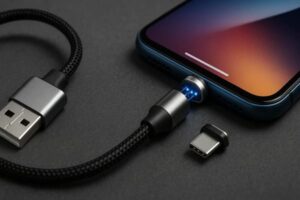
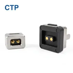
Selecting a magnetic pogo pin connector should begin with the product
interface requirements rather than pin count, magnet grade or a catalog
model. Engineers should first define what crosses the interface, then build
the mechanical stack-up, establish pogo pin working stroke, validate the
complete power and signal paths, define magnetic capture and release
behavior, evaluate environmental states and convert the approved design into
controlled production requirements. The following seven rules provide a
practical workflow from prototype definition to production release.
Why Magnetic Pogo Pin Connector Selection Often Fails at the Prototype Stage
Many magnetic connector projects begin with a question such as:“Do you have a 4-pin magnetic connector that can carry my current?”
That sounds reasonable, but it starts too late in the engineering process.
Pin count and connector shape are outputs of the product architecture.
They should not be the starting assumptions.
A magnetic pogo pin interface combines several different functions:- mechanical approach;
- magnetic capture;
- final positioning;
- spring-loaded electrical contact;
- power transmission;
- signal or detection paths;
- environmental exposure;
- repeated mating and service.
If these requirements are not defined together, the first prototype can
appear functional while still containing hidden tolerance, thermal,
partial-mating or manufacturability risks.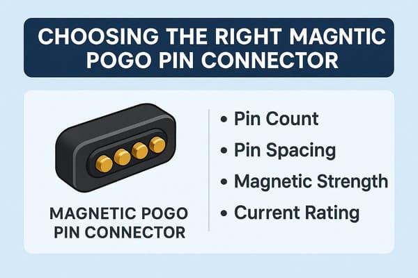
into mechanical, electrical and production specifications before the
geometry is frozen.
Rule 1: Define the Interface Contract Before Choosing the Connector
The first engineering task is not choosing a magnetic connector.

It is defining what the two sides of the product must exchange.

This can be treated as an interface contract.| Interface Layer | Questions to Define |
|---|---|
| Mechanical | How do the two modules approach, locate, retain and separate? |
| Power | What voltage, continuous current and peak current are required? |
| Return | How many return paths are required and where are they located? |
| Detection | Does the system need to know that the module is present? |
| Identification | Does the host need to identify the accessory or module? |
| Signals | What control or communication channels cross the interface? |
| Environment | What happens when the interface is mated, partially mated or exposed? |
| Lifecycle | How frequently will the interface connect and disconnect? |
Pin Count Should Come from the Pin Map
A common mistake is selecting a 4-pin, 6-pin or 24-pin connector first and
then attempting to fit the electrical functions into the available contacts.

A stronger process is:


    Required Functions
    →
    Pin Map
    →
    Contact Allocation
    →
    Connector Geometry


For example, a removable module may need:- power;
- power return;
- connection detection;
- module identification;
- control signals;
- data paths where applicable.
Only after these functions are defined should the required contact count be
finalized.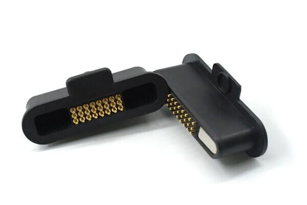
functions should be defined before the contact layout is frozen.
Rule 2: Build the Mechanical Stack-Up Around Working Stroke
The pogo pin should reach a defined working compression only after the two
product halves reach their final mechanical position.
A simplified relationship is:
S = Hfree - Hseatedwhere:
- S is actual pogo pin compression;
- Hfree is installed free height;
- Hseated is installed height after final mating.
The important word is final.

Magnetic attraction should not be the feature that defines the final
electrical geometry.
Use Mechanical Features to Establish Position
A controlled architecture normally separates the functions:
| Function | Preferred Control |
|---|---|
| Initial Attraction | Magnetic system |
| Orientation | Housing geometry / mechanical coding |
| Final X-Y Position | Mechanical datums |
| Final Z Position | Mechanical stop |
| Electrical Compliance | Pogo pin working stroke |
Total Travel Is Not the Normal Working Position
A pogo pin may have additional mechanical travel beyond the intended
operating range.

That total travel should not automatically be used as the normal assembled
position.

Repeated bottoming can increase stress on:- the spring-loaded contact;
- the mating target;
- the PCB;
- the solder joint;
- the connector housing.
Build a Real Tolerance Stack
The final pogo pin compression can vary because of:- pogo pin free-height tolerance;
- PCB thickness;
- solder height;
- housing dimension;
- target-pad height;
- module flatness;
- mechanical-stop tolerance;
- assembly variation.
The prototype should therefore be checked at minimum, nominal and maximum
stack-up conditions rather than only at nominal CAD dimensions.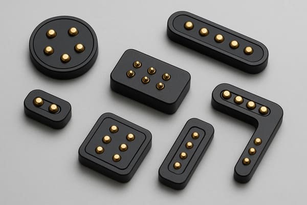
installed height, working stroke and the complete mechanical stack-up.
Rule 3: Size Power from the Complete Electrical Path
One of the most common selection questions is:

“How many amps can this pogo pin carry?”

The answer cannot be derived from plunger material or diameter alone.
A complete power path can include:
    Power Source
    →
    PCB / Cable
    →
    Termination
    →
    Pogo Pin
    →
    Contact Interface
    →
    Target
    →
    Device PCB
    →
    Load
The total resistance may be represented as:
    Rpath =
    Rsource +
    Rcable/PCB +
    Rtermination +
    Rpogo +
    Rinterface +
    Rtarget +
    Rdevice
Voltage drop is:
Vdrop = I × RpathResistive loss is:
Ploss = I² × Rpath

Current selection should therefore include:- continuous current;
- peak current;
- duty cycle;
- working stroke;
- contact resistance;
- termination resistance;
- ambient temperature;
- allowed temperature rise;
- target-pad structure.
Do Not Start with a Fixed Alloy Recipe
Copper alloys and other contact materials can be selected for specific
combinations of conductivity, mechanical performance, wear and
manufacturability.

However, specifying one material such as BeCu or CuCrZr does not by itself
establish a current rating.

Material selection should follow the approved electrical, mechanical and
lifecycle requirements.
Parallel Contacts Need Current-Sharing Validation
Multiple pogo pins may be connected in parallel for power or return.

Current will not necessarily divide equally.
Branch current can change because of:
- working-stroke variation;
- contact-resistance variation;
- target flatness;
- module tilt;
- PCB routing;
- termination resistance.
A prototype power array should therefore be evaluated for both
complete-path temperature rise and
current distribution.
Rule 4: Treat Signals and Data as a Channel Problem
Adding signal contacts to a magnetic pogo pin connector is not the same as
proving compatibility with a communication protocol.

Pin count alone does not establish bandwidth.

Complete-channel performance can depend on:- signal-to-return allocation;
- contact geometry;
- contact pitch;
- PCB launch geometry;
- FPC or cable architecture;
- reference-path continuity;
- crosstalk;
- channel length;
- termination and receiver architecture.
Design the Return Path at the Same Time as the Signal Path
Engineers sometimes assign several pins to “data” and then add ground
contacts later.

For signal-sensitive interfaces, return-path geometry should be considered
at the same time as signal allocation.

A stronger workflow is:


    Signal Requirement
    →
    Signal / Return Architecture
    →
    Pin Map
    →
    PCB / Cable Transition
    →
    Channel Validation
A Metal Housing Is Not Automatically an EMI Shield
A conductive connector housing may contribute to shielding, but it does not
automatically form an effective Faraday cage.
EMC performance can depend on:
- housing continuity;
- gaps and apertures;
- ground connection;
- PCB reference planes;
- signal return paths;
- cable shield termination;
- complete system grounding.
EMI should therefore be validated at the product or channel level rather
than inferred from housing material.
Rule 5: Specify Magnetic Behavior as Multiple Requirements
Magnetic force should not be treated as one number.

The connector can behave differently during approach, normal use and
removal.| Magnetic / Mechanical Behavior | Engineering Question |
|---|---|
| Capture | How should the connector behave during approach? |
| Final Seating | What mechanical feature defines the final position? |
| Seated Retention | What loads must the interface tolerate during normal use? |
| Axial Separation | How much force is required for straight removal? |
| Peel Separation | How should the connector release from one edge? |
| Off-Axis Load | How does cable or module twisting affect the connection? |
Stronger Magnets Are Not Automatically Better
Excessive attraction can create:- higher closing impact;
- greater removal effort;
- more lateral sliding during capture;
- higher housing load;
- reduced breakaway behavior;
- more attraction of ferromagnetic debris.
Magnetic design should therefore begin from the required mechanical
behavior rather than a predetermined magnet grade.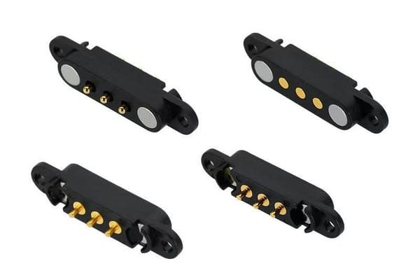
separate mechanical requirements.
Rule 6: Define Every Environmental State of the Interface
Engineers often ask whether a connector can be “waterproof.”

A more useful question is:

Which part of the complete assembly is the environmental boundary?
The boundary may include:
- pogo pin feedthroughs;
- connector housing;
- housing-to-device joint;
- target-pad installation;
- gaskets;
- potting or insert molding;
- PCB, FPC or wire termination;
- other enclosure openings.
Do Not Evaluate Only the Fully Mated State
| Interface State | Engineering Question |
|---|---|
| Fully Mated | Are electrical and environmental conditions within limits? |
| Partially Mated | Can some contacts energize before final seating? |
| Unmated | Are conductive contacts exposed to users or contaminants? |
| Contaminated | Can debris prevent working stroke or target contact? |
| After Cleaning | Can liquid residue remain around the connector? |
Visible Sealing Features Do Not Prove an IP Rating
An O-ring, potting compound or insert-molded structure can contribute to
environmental protection.

It does not automatically establish IP68, IP69K or another ingress rating.

The rating applies only to the defined and tested assembly under the
applicable conditions.
Magnets Add a Contamination Mechanism
Ferromagnetic particles can be attracted toward the interface.They may:
- prevent full seating;
- change pogo pin compression;
- scratch target surfaces;
- bridge adjacent conductive areas;
- increase contact resistance.
Industrial, workshop and outdoor applications should therefore include
realistic debris conditions during validation.
Rule 7: Convert the Prototype into Controlled Production Requirements
A prototype that works once is not yet a production-ready connector.

Before release, the engineering team should define the characteristics that
must remain controlled from lot to lot.
These are the connector’s critical-to-quality characteristics, or CTQs.
| CTQ Area | Possible Controlled Requirement |
|---|---|
| Pin Geometry | Pitch, installed height and contact position |
| Working Stroke | Approved operating compression range |
| Contact Force | Force at the defined working stroke |
| Electrical | Resistance or voltage-drop test condition |
| Magnetic System | Polarity, orientation and approved retention behavior |
| Mating Target | Geometry, flatness and surface specification |
| Housing | Critical dimensions and datum features |
| Termination | PCB, FPC, wire or cable requirements |
| Traceability | Lot, revision and process records where required |
The Engineering Drawing Should Become the Interface Contract
The approved drawing should define the characteristics that cannot be left
to interpretation during production.
Depending on the project, this may include:
- connector outline dimensions;
- Pin Map;
- pin pitch;
- installed height;
- working stroke;
- contact-force requirement;
- mating target;
- critical material or finish requirements;
- magnet polarity;
- mechanical datums;
- termination;
- inspection requirements;
- drawing revision.
Do Not Treat the Golden Sample as the Specification
A physical sample is useful for confirming:- fit;
- feel;
- mating behavior;
- appearance;
- prototype functionality.
But a golden sample cannot communicate every allowable dimensional,
electrical and material tolerance.

Production should therefore be controlled by the approved drawing,
specification and agreed validation requirements, with the sample acting as
supporting reference where useful.
AOI Does Not Validate Every Pogo Pin Characteristic
Automated optical inspection can verify certain visible dimensions,
orientation and assembly characteristics.

It cannot automatically verify:- internal spring behavior;
- contact force at working stroke;
- contact resistance under the required condition;
- internal plating condition;
- lifecycle performance;
- temperature rise;
- magnetic retention under all directions.
Inspection methods should therefore be matched to each CTQ.Tape-and-Reel Does Not Automatically Mean SMT-Ready
Packaging format and assembly-process compatibility are separate
requirements.

For a surface-mount pogo pin or connector, engineers may need to review:- PCB pad design;
- pick-up surface;
- nozzle accessibility;
- component center of gravity;
- reflow compatibility;
- solder paste volume;
- post-reflow installed height;
- coplanarity.
Prototype Validation Should Include Worst-Case Conditions
One nominal prototype is not enough to prove that the production tolerance
window is robust.
A useful engineering prototype program should evaluate:
- minimum working stroke;
- nominal working stroke;
- maximum working stroke;
- X-Y offset;
- angular misalignment;
- partial mating;
- normal and abnormal cable or module loads;
- relevant environmental conditions;
- electrical loading;
- repeated mating.
A Practical Prototype-to-Production Validation Plan
| Stage | Primary Goal | Typical Engineering Output |
|---|---|---|
| Concept Review | Confirm architecture feasibility | Interface contract and initial Pin Map |
| Mechanical Prototype | Confirm geometry and mating behavior | Datums, stroke and retention range |
| Electrical Prototype | Confirm power and signal paths | Voltage-drop, temperature and channel results |
| Environmental Prototype | Evaluate application exposure | Post-exposure electrical and mechanical data |
| Lifecycle Prototype | Evaluate degradation | Resistance, wear and force trends |
| Design Freeze | Control the approved interface | Released drawing and CTQs |
| Pilot Production | Confirm repeatability | Process data and inspection results |
| Production Release | Maintain controlled output | Revision, traceability and change-control system |
Supplier Selection Should Follow the Critical Requirements
A supplier should not be selected only because it shows automated equipment
or a large factory.

The more useful question is:


    Can the supplier consistently control the characteristics that determine
    the performance of this specific connector?
Supplier review may include:
- drawing-control process;
- measurement capability for critical dimensions;
- contact-force testing where required;
- electrical-resistance test capability;
- magnetic polarity and force control;
- material and plating traceability where required;
- lot traceability;
- engineering change control;
- prototype-to-production consistency;
- capacity relevant to the actual project.
Quality-system or regulatory certificates should only be treated as
applicable when the actual supplier, manufacturing site and scope are
covered by valid documentation.
traceability and change control rather than factory scale alone.
Magnetic Pogo Pin Connector Selection Checklist
| Selection Area | Questions to Answer Before Design Freeze |
|---|---|
| Application | What are the two modules being connected? |
| Mating Frequency | How often will the interface connect and disconnect? |
| Available Space | What X, Y and Z envelope is available? |
| Pin Map | What does each contact do? |
| Working Stroke | What are minimum, nominal and maximum compression? |
| Mechanical Alignment | What X-Y-Z and angular tolerances exist? |
| Current | What continuous and peak current must the interface carry? |
| Signal | What protocol or signal requirements apply? |
| Magnetic Capture | How should the connector behave during approach? |
| Retention | How strongly must the connector remain seated? |
| Breakaway | How should the connector release under axial and peel loads? |
| Environment | What temperature, water, sweat, dust or chemicals are expected? |
| Lifecycle | What test conditions and end-of-life criteria apply? |
| Manufacturing | How will the component be mounted, assembled and inspected? |
| Change Control | Which product or process changes require customer approval? |
Information Required for a Custom Magnetic Pogo Pin Connector Review
Providing complete project information early can reduce the number of
prototype iterations.| Project Input | Information to Provide |
|---|---|
| Application | Charging, docking, wearable, module, industrial equipment or another interface |
| Product Architecture | Which two assemblies must mate? |
| Available Space | X, Y and Z limits |
| Pin Map | Function of each contact |
| Electrical Conditions | Voltage, continuous current and peak current |
| Signal Requirement | Power only, control or defined data requirement |
| Mating Direction | Axial, side docking or project-specific approach |
| Mechanical Tolerance | X-Y-Z and angular variation |
| Working Stroke | Available or target compression window |
| Magnetic Behavior | Capture, seated retention and separation requirement |
| Environment | Temperature, water, sweat, dust, oil or chemical exposure |
| Lifecycle | Expected mating profile and end-of-life criteria |
| Mounting | PCB, FPC, wire, cable or another termination |
| Project Files | 2D drawing, 3D model, PCB layout or complete assembly |
Frequently Asked Questions
How do I choose the right magnetic pogo pin connector?
Start by defining the interface function, Pin Map, available mechanical
space, working stroke, electrical load, signal requirements, magnetic
behavior, environment and lifecycle before selecting the final connector
geometry.
Should I choose pin count first?
Usually no. Define the required power, return, detection, identification and
signal functions first, then derive the required Pin Map and contact count.
How do I determine pogo pin working stroke?
Working stroke is determined from the installed free height and the final
mechanically seated height. The complete tolerance stack should be checked
at minimum, nominal and maximum conditions.
Can I choose a magnetic pogo pin connector from current rating alone?
No. Current capability depends on the complete conductive path, including
PCB or cable, termination, pogo pin, contact interface, target and device
electronics, as well as temperature rise and duty cycle.
Can multiple pogo pins be connected in parallel for more current?
Yes, but branch currents may not divide equally. Working stroke, contact
resistance, target flatness, PCB routing and termination should be included
in current-sharing validation.
How many pins are needed for high-speed data?
Pin count alone does not determine bandwidth. The signal-to-return
architecture, contact geometry, PCB transitions, cable structure and
complete channel must be designed for the intended signal.
Are stronger magnets always better?
No. Stronger attraction can increase retention but can also increase
closing impact, removal force, lateral sliding and metallic-debris
attraction.
How should magnetic force be specified?
Define capture behavior, seated retention, axial separation, peel
separation and off-axis behavior separately rather than using one magnetic
force value for every mechanical condition.
Are magnetic pogo pin connectors automatically waterproof?
No. Environmental protection depends on the complete housing, contact
feedthroughs, seals, targets, termination and tested assembly configuration.
Does tape-and-reel mean the connector is SMT compatible?
No. SMT compatibility also depends on pad design, pick-up geometry, reflow
compatibility, solder process, component balance and post-reflow installed
height.
Is AOI enough for magnetic pogo pin quality control?
No. AOI can inspect selected visible characteristics but cannot replace
electrical resistance, contact-force, magnetic, lifecycle and other
project-specific tests.
What should be frozen before mass production?
The approved drawing should define the critical interface geometry, Pin Map,
working stroke, mechanical datums, electrical requirements, materials or
finishes where necessary, termination, inspection requirements and revision
control.
What information should I send a magnetic connector manufacturer?
Provide the product architecture, available space, Pin Map, voltage,
current, signal requirements, mating direction, working stroke, magnetic
behavior, environment, lifecycle target and 2D or 3D project files.
Request a Magnetic Pogo Pin Connector Engineering Review
Explore

    custom magnetic connector solutions

for removable charging, docking and modular interfaces.

Review

    pogo pin and spring-contact solutions

for project-specific contact layouts and mounting structures.

Learn more about CTP engineering and manufacturing capabilities on the

    About Us page
.

Submit your Pin Map, available space, voltage, current, working stroke,
magnetic requirements and project drawings through the

    Get Quote & Samples page
.


    CTP can review connector geometry, Pin Map, pogo pin working stroke,
    mating targets, magnetic capture, seated retention, breakaway behavior
    and PCB, FPC, wire or cable termination for custom magnetic pogo pin
    connector projects. Final current capability, signal performance,
    environmental protection, lifecycle and production tolerances depend on
    the approved connector design and project-specific validation.
CTP ENGINEERING PATHS
Choose the right path for your project
Move from application requirements to a connector pair, a data-capable cable assembly, or a charging cable configuration. Final specifications are confirmed against an approved drawing and project validation plan.
Magnetic Connectors
Connector geometry, pin layout, mechanical integration and OEM/ODM review.
Engineering overview → 02Magnetic Data Cables
Power and signal allocation, cable exit, interface selection and assembly review.
Cable engineering → 03Magnetic Charging Cables
Browse the complete cable catalog and shortlist a starting structure for customization.
View cable catalog →