
Engineering Summary:
Choosing between pogo pins and traditional connectors should not begin with
a universal mating-cycle number. The correct architecture depends on how
often the interface mates, whether positive locking is required, how the
product is serviced, what mechanical tolerances exist, what power and
signals cross the interface, how the connector is exposed to the
environment and whether standardized interoperability is required.
Pogo pins are particularly useful for frequently removable, docked,
test and modular interfaces. Conventional connectors often remain the
better choice for standardized, permanently secured or very high-density
connections.
Choosing between pogo pins and traditional connectors should not begin with
a universal mating-cycle number. The correct architecture depends on how
often the interface mates, whether positive locking is required, how the
product is serviced, what mechanical tolerances exist, what power and
signals cross the interface, how the connector is exposed to the
environment and whether standardized interoperability is required.
Pogo pins are particularly useful for frequently removable, docked,
test and modular interfaces. Conventional connectors often remain the
better choice for standardized, permanently secured or very high-density
connections.
The Real Question Is Not “Which Connector Is Better?”
Engineers often compare pogo pins and conventional connectors by asking
which one has the longer mating life or smaller footprint.
That comparison is incomplete.
Connector architecture should be selected from the function of the
interface.
A USB receptacle, board-to-board connector, wire harness connector,
FFC/FPC connector and pogo pin array are designed around different
mechanical and electrical requirements.
The more useful engineering question is:
What does this electrical interface need to do during the complete
product lifecycle?
Their value depends on the mechanical and electrical function of the
complete interface.
First Define the Connector Architecture You Are Comparing
“Traditional connector” is too broad to describe one mechanical principle.

Different connector families operate differently.| Architecture | Typical Characteristic | Common Reason to Use It |
|---|---|---|
| Pogo Pin / Spring Contact | Axial spring compliance against a mating target | Repeated removable contact, docking, test or modules |
| Magnetic Pogo Pin | Spring contacts plus magnetic capture / retention | Blind mating, docking or controlled removable interfaces |
| Plug and Receptacle | Defined male / female insertion interface | Standard external I/O and interoperability |
| Board-to-Board | High-density PCB-to-PCB connection | Internal compact electronic assemblies |
| FFC / FPC | Flexible high-density interconnect | Internal displays, cameras and compact modules |
| Wire / Harness Connector | Often includes positive locking | Permanent or semi-permanent wired connections |
This distinction matters because a pogo pin should not be compared with all
of these architectures using one lifecycle number.
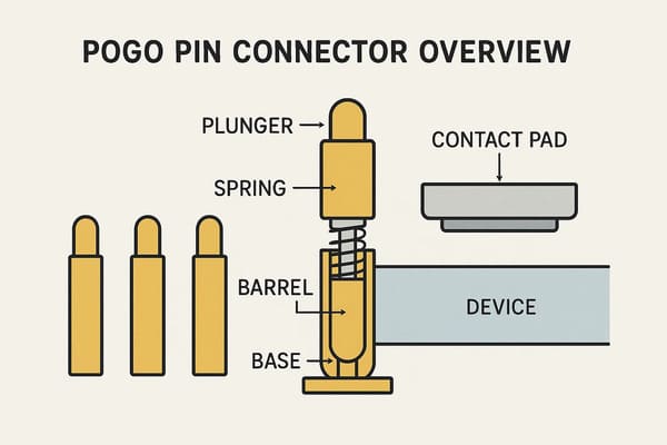
How Does a Pogo Pin Interface Work?
A pogo pin is a spring-loaded electrical contact.

A common structure includes:- a moving plunger;
- an internal spring;
- a guiding barrel or body;
- a termination to the PCB, wire or another conductive structure.
When the mating target reaches the connector, the plunger compresses and
the spring creates contact force.
A simplified relationship is:
S = Hfree - Hworkingwhere:
- S = working compression;
- Hfree = installed free height;
- Hworking = installed height in the final mating state.
This controlled axial movement is the main mechanical feature that
distinguishes spring contacts from many fixed-contact interfaces.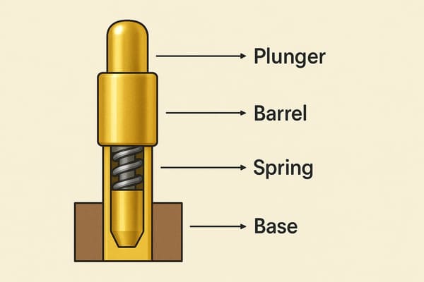
force, resistance and working stroke depend on the selected design.
Decision Factor 1: How Often Will the Interface Be Mated?
Mating frequency is one of the strongest reasons to evaluate pogo pins,
but cycle count should be handled carefully.

Consider three different products:| Product Interface | Expected Interaction | Likely Design Priority |
|---|---|---|
| Internal PCB Connector | Mated once during assembly | Density, cost and secure retention |
| Service Module | Removed several times during product life | Serviceability and reliable remating |
| Charging / Docking Interface | Connected repeatedly | Wear, alignment and maintenance |
| Production Test Fixture | Very frequent temporary contact | Repeatability and replaceable wear components |
As mating frequency increases, the value of a spring-loaded removable
interface can increase.

But this does not mean every pogo pin automatically achieves a specific
number of cycles.
Cycle Life Requires Test Conditions
A meaningful lifecycle statement should define:- working stroke;
- contact force;
- mating target;
- target finish;
- mating angle and speed;
- electrical load;
- environment;
- measurement intervals;
- end-of-life criteria.
Therefore:


    “a model-specific cycle-life target validated under defined test conditions” without test conditions is not enough information to
    select a connector architecture.
Decision Factor 2: Does the Connection Need Positive Locking?
This is one area where a conventional connector may have a clear advantage.

Many wire, circular and industrial connectors provide:- mechanical latches;
- threaded locking;
- bayonet locking;
- secondary locking features;
- defined cable strain relief.
These architectures are useful when the primary requirement is:


    “Once connected, this interface should not separate accidentally.”
Pogo Pin Interfaces Solve a Different Mechanical Problem
A pogo pin interface is often more useful when the goal is:- frequent removal;
- fast docking;
- low insertion effort;
- automatic contact;
- serviceable modules;
- temporary electrical access.
If magnets are added, the designer can also define capture, retention and
breakaway behavior.

However, magnetic retention should not automatically be treated as the
equivalent of a positive mechanical lock.
Decision Factor 3: How Should the Interface Handle Misalignment?
Pogo pins can accommodate controlled variation along their spring axis.

This is useful when the final mating height varies slightly because of:- PCB tolerance;
- housing tolerance;
- target height;
- module flatness;
- assembly variation.
However:


    Pogo pin compliance does not automatically correct large X-Y or angular
    misalignment.


A controlled architecture should normally separate:| Function | Design Element |
|---|---|
| Coarse Position | Housing / device structure |
| X-Y Alignment | Mechanical guides or datums |
| Final Z Position | Mechanical stop |
| Electrical Compliance | Pogo pin working stroke |
| Capture where required | Magnetic system |
Total Travel Is Not Recommended Working Stroke
A pogo pin may physically travel farther than its normal working range.

The surrounding product should establish the mechanical stop rather than
repeatedly bottoming the spring-loaded contact.
Decision Factor 4: What Happens When the Connector Is Unmated?
This question is especially important when comparing a pogo pin interface
with a recessed plug-and-receptacle structure.

Pogo pin architectures can use relatively flat external contact surfaces,
but those contacts may remain exposed when the product is disconnected.
The empty state should consider:
- water or condensation;
- skin oils and sweat;
- dust;
- cleaning fluids;
- conductive objects;
- metallic debris where magnets are used;
- whether exposed contacts remain energized.
Flat Contacts Do Not Automatically Mean IP68
A shallow interface can simplify some enclosure designs, but ingress
protection depends on the complete sealing boundary.
This may include:
- contact feedthroughs;
- housing joints;
- gaskets;
- potting or insert molding;
- PCB or wire terminations;
- target mounting;
- other openings in the enclosure.
An IP rating should only be associated with the actual tested assembly and
condition.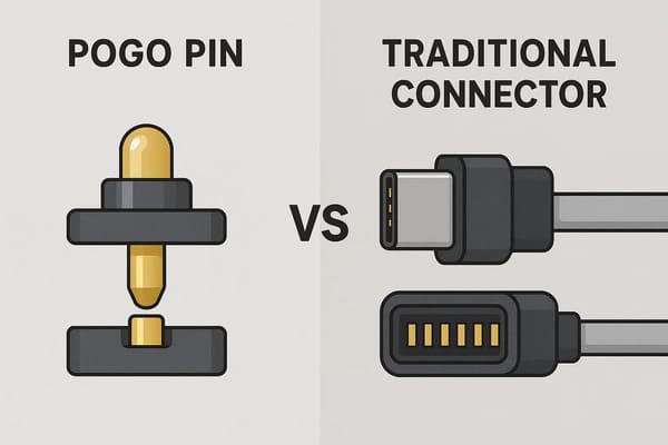
electrical, environmental and service functions—not a universal ranking.
Decision Factor 5: What Power Must Cross the Interface?
Pogo pins can be designed as part of power interfaces, but current
capability should never be inferred from the connector category alone.
A complete power path can include:
    Power Source
    →
    PCB / Cable
    →
    Termination
    →
    Pogo Pin
    →
    Contact Interface
    →
    Target
    →
    Load
The complete path resistance can be represented as:
    Rpath =
    Rsource +
    Rtermination +
    Rpogo +
    Rinterface +
    Rtarget +
    Rload
Voltage drop is:
Vdrop = I × Rpathand resistive loss is:
Ploss = I² × Rpath

Engineers should evaluate:- continuous current;
- peak current;
- working stroke;
- temperature rise;
- termination resistance;
- mating-target condition;
- ambient temperature;
- duty cycle.
Parallel Pogo Pins Require Current-Sharing Validation
Several contacts may be connected in parallel, but the current does not
necessarily divide equally.

Differences can come from contact resistance, working stroke, target
flatness, routing and module tilt.
Decision Factor 6: What Data or Signal Performance Is Required?
This is one of the strongest areas where engineers should avoid assuming
that pogo pins are automatically superior.

A standardized high-speed connector can provide a well-defined mechanical
and electrical ecosystem.

A custom pogo pin interface may provide more geometry freedom, but the
signal channel must be engineered accordingly.
High-speed performance can depend on:
- signal-return allocation;
- contact pitch;
- contact geometry;
- PCB transitions;
- reference-plane continuity;
- cable construction;
- crosstalk;
- complete channel length.
Therefore:


    More pogo pins do not automatically mean more bandwidth.
Short Contacts Do Not Automatically supports Signal Integrity
Short conductive paths can be beneficial in some designs, but the complete
channel still determines actual performance.

A particular USB, Ethernet, RF or other high-speed interface should only be
claimed after appropriate channel design and validation.
Decision Factor 7: Do You Need Standardized Interoperability?
This is one of the clearest reasons a conventional connector may be the
better architecture.

Standard connector ecosystems can provide:- third-party accessories;
- defined mechanical interfaces;
- established cables;
- known pin assignments;
- existing test methods;
- multi-supplier availability.
A custom pogo pin interface provides more design freedom, but that freedom
can also create a proprietary ecosystem.
Custom Interface Freedom Comes with Governance Requirements
If several products share one custom connector, the engineering team should
control:- connector geometry;
- Pin Map;
- voltage compatibility;
- current limits;
- magnetic polarity where used;
- device identification;
- future product revisions.
Physical mating alone should not be treated as proof of electrical
compatibility.
Decision Factor 8: What Is the Service Strategy?
Serviceability is often one of the strongest reasons to use spring contacts.

A connector architecture can be designed so that the expected wear occurs
on a lower-cost replaceable component rather than on the main PCB.
Possible replaceable elements include:
- charging cables;
- docking plates;
- contact modules;
- test probes;
- mating targets.
This creates an important lifecycle question:


    Which side of the interface should be the serviceable wear component?
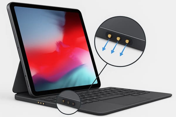
architectures when serviceability and repeated mating are important.
Pogo Pins and Traditional Connectors: Engineering Comparison
| Requirement | Pogo Pin Architecture | Conventional Connector Architecture |
|---|---|---|
| Frequent Removable Mating | Often a strong candidate | Depends heavily on selected connector family |
| Blind Docking | Well suited with proper guidance | Possible with dedicated blind-mate designs |
| Positive Mechanical Lock | Requires additional structure if needed | Many connector families provide integrated locking |
| Spring Z Compliance | Inherent to pogo pin architecture | Depends on connector design |
| Custom Pin Map | High design freedom | Often predefined by connector family |
| Standard Interoperability | Usually lower for custom interfaces | Often a major advantage |
| Very High Contact Density | Requires careful packaging review | Dedicated board-to-board / FPC solutions may be better |
| Exposed Flat Interface | Possible | Depends on architecture |
| Serviceable Wear Element | Can be deliberately designed | Depends on connector placement |
| Automated Docking | Strong application area | Requires compatible blind-mate architecture |
| High-Speed Standard Protocol | Requires custom channel validation | Standardized connector often advantageous |
| Permanent Internal Connection | May add unnecessary complexity | Often more appropriate |
Where Pogo Pins Usually Make the Most Engineering Sense
Pogo pin connectors are especially worth evaluating for:
- charging docks;
- removable battery modules;
- wearable charging interfaces;
- industrial docking stations;
- production test fixtures;
- temporary programming interfaces;
- replaceable electronic modules;
- service contacts;
- robotic charging and docking;
- custom accessory ecosystems.
Where a Traditional Connector May Be the Better Choice
A conventional connector is often preferable when:
- the connection is mated once and remains internal;
- positive locking is essential;
- third-party compatibility is required;
- a standardized external interface is required;
- very high contact density is needed;
- a standardized high-speed channel is the primary requirement;
- custom connector development provides little lifecycle benefit.

locking, contact density or permanent connection is more valuable than
repeated spring-loaded mating.
Do Not Make the Decision from Connector Unit Price Alone
Connector cost and system cost are different.

The correct comparison may need to include:- connector unit cost;
- PCB space;
- housing complexity;
- assembly method;
- custom tooling;
- cable cost;
- service time;
- replacement strategy;
- accessory compatibility;
- field maintenance;
- expected mating frequency.
A lower-cost connector is not automatically the lower-cost system.

Likewise, a more expensive pogo pin architecture does not automatically
reduce total cost.

The economics depend on how the interface is used.
A Practical Connector Architecture Decision Tree
A useful early-stage decision sequence is:


    Does the Interface Need to Be Removable?
    ↓
    How Frequently Will It Mate?
    ↓
    Is Blind or Automated Docking Required?
    ↓
    Is Positive Locking Required?
    ↓
    Is Standardized Interoperability Required?
    ↓
    What Power and Signals Cross the Interface?
    ↓
    What Is the Environmental Exposure?
    ↓
    Which Component Should Be Serviceable?
    ↓
    Compare Connector Architectures
Strong Pogo Pin Indicators
- frequent mating;
- temporary contact;
- blind docking;
- automated connection;
- replaceable module;
- serviceable wear interface;
- custom mechanical geometry.
Strong Conventional Connector Indicators
- permanent or semi-permanent connection;
- positive mechanical locking;
- standard ecosystem compatibility;
- very high contact density;
- established high-speed interface;
- low mating frequency.
Recommended Validation Plan Before Final Connector Selection
| Validation Area | Engineering Evaluation |
|---|---|
| Interface Duty | Define actual mating frequency and use profile |
| Mechanical Alignment | Evaluate X-Y-Z and angular tolerance |
| Working Stroke | Verify minimum, nominal and maximum pogo compression |
| Retention | Evaluate required normal and abnormal loads |
| Electrical Resistance | Measure complete intended contact path |
| Power | Evaluate voltage drop and temperature rise |
| Signal Channel | Validate required channel performance |
| Partial Mating | Evaluate incomplete and tilted connection states |
| Environment | Test actual moisture, dust, chemicals and temperature conditions |
| Lifecycle | Use representative mating motion and failure criteria |
| Serviceability | Confirm cleaning and replacement strategy |
| Manufacturing | Review PCB, housing, assembly and inspection processes |
Information Needed for a Connector Architecture Review
| Project Input | Information to Provide |
|---|---|
| Application | Charging, docking, internal PCB, module, cable, service or test |
| Mating Frequency | Expected use profile |
| Available Space | X, Y and Z envelope |
| Retention | Positive lock, magnetic retention or easy removal? |
| Pin Map | Power, return, detection and signal functions |
| Electrical Conditions | Voltage, continuous current and peak current |
| Signal Requirement | Protocol or channel requirements where applicable |
| Mechanical Tolerance | X-Y-Z and angular variation |
| Environment | Temperature, moisture, dust, chemicals and contamination |
| Standardization | Whether third-party compatibility is required |
| Service Strategy | Which side should be inspectable or replaceable? |
| Lifecycle Requirement | Expected mating profile and end-of-life criteria |
Frequently Asked Questions
Are pogo pins better than traditional connectors?
Not universally. Pogo pins are particularly useful for frequently removable,
docked, test and service interfaces, while conventional connectors may be
better for standardized, locked or permanent connections.
Do pogo pins last longer than USB connectors?
A universal comparison is not meaningful without specific connector models,
working stroke, mating conditions, electrical load, environment and
end-of-life criteria.
Are pogo pins wear-free?
No. Pogo pin tips and mating targets can wear during repeated use, especially
when lateral sliding, contamination or excessive compression is present.
Can pogo pins replace USB connectors?
They can replace the physical interface in some custom products, but USB
provides standardized electrical and ecosystem requirements that a custom
pogo pin interface must reproduce and validate separately where required.
Are pogo pin connectors automatically magnetic?
No. Pogo pins are spring-loaded contacts. Magnets are optional components
used in some connector architectures for capture and retention.
Are pogo pins suitable for high-current applications?
They can form part of a higher-current interface, but capability depends on
the complete electrical path, contact resistance, working stroke,
termination, current sharing and temperature rise.
Can pogo pins carry high-speed data?
Potentially, but pin count does not define bandwidth. Signal-return layout,
contact geometry, PCB transitions, cable construction and complete-channel
performance must be evaluated.
Are pogo pin connectors easier to waterproof?
A flat contact surface can simplify some enclosure designs, but ingress
protection still depends on the complete connector and product sealing
architecture.
When should I choose pogo pins?
Consider pogo pins when the interface requires repeated removable mating,
blind docking, automated contact, test access, modular replacement or a
serviceable contact surface.
When should I use a traditional connector instead?
A conventional connector may be better when positive locking,
standardization, third-party compatibility, permanent mating or very high
contact density is the primary requirement.
What determines pogo pin lifecycle?
Lifecycle depends on working stroke, contact force, target geometry,
surface finish, mating motion, electrical load, contamination, environment
and the criteria used to define end of life.
How should engineers compare connector cost?
Compare total interface cost rather than unit price alone, including PCB and
housing design, assembly, tooling, service, replacement, compatibility and
expected mating frequency.
Request a Connector Architecture Engineering Review
Review

    pogo pin and spring-contact solutions

for test, docking, charging and removable electronic interfaces.

For magnet-assisted interfaces, explore

    custom magnetic connector solutions
.

Submit your mating frequency, available space, Pin Map, voltage, current,
signal requirements, retention needs and product drawings through the

    Get Quote & Samples page
.


    CTP can review pogo pin contact layout, working stroke, mating targets,
    magnetic capture where required, PCB, FPC, wire or cable termination
    and alternative connector architectures for custom hardware projects.
    Final connector selection should be based on the complete mechanical,
    electrical, environmental, lifecycle and service requirements of the
    product.

