Engineering Summary:
The magnetic pogo pin connector market is better understood through changes
in hardware architecture than through one market-size forecast. Demand is
increasing in applications where the electrical interface must also support
repeated removal, blind docking, modular replacement, automated connection
or a product-specific mechanical boundary. Magnetic capture and spring-loaded
contacts can address these requirements, but they are not universal
replacements for standardized or permanently locked connectors. Engineers
should evaluate the interface from the complete mechanical, electrical,
environmental and service architecture.
The magnetic pogo pin connector market is better understood through changes
in hardware architecture than through one market-size forecast. Demand is
increasing in applications where the electrical interface must also support
repeated removal, blind docking, modular replacement, automated connection
or a product-specific mechanical boundary. Magnetic capture and spring-loaded
contacts can address these requirements, but they are not universal
replacements for standardized or permanently locked connectors. Engineers
should evaluate the interface from the complete mechanical, electrical,
environmental and service architecture.
What Is Actually Driving the Magnetic Pogo Pin Connector Market?
Connector markets do not grow simply because one contact technology becomes
more fashionable.
They grow when the architecture of the products around them changes.
A conventional plug-and-receptacle connector is highly effective when an
interface is standardized, mechanically locked and expected to remain
connected for long periods.
Different requirements appear when the product must instead be:- connected and disconnected frequently;
- docked without precise manual alignment;
- divided into removable functional modules;
- charged automatically;
- serviced without disturbing the main assembly;
- designed around a custom external surface;
- shared across multiple products in one platform.
These changes create a different connector problem.

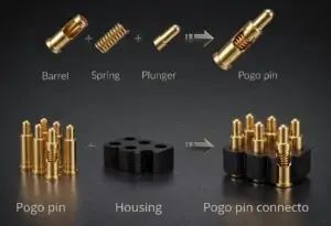
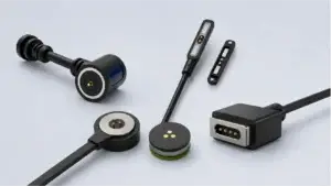
A magnetic pogo pin interface combines:- spring-loaded conductive contacts;
- a removable mating target;
- magnet-assisted capture or retention where required;
- project-specific housing and mechanical geometry.
The resulting value comes less from one individual component and more from
the ability to customize the complete interface around the product.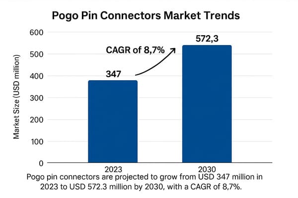
docking, serviceability and custom product-interface requirements rather
than one universal connector-performance advantage.
Trend 1: The Electrical Connector Is Becoming a Module Boundary
One of the most important changes in modern hardware is the separation of a
complete product into replaceable or removable functional modules.
Examples can include:
- removable battery packs;
- sensor modules;
- tablet keyboards;
- charging bases;
- wearable accessories;
- industrial tool heads;
- replaceable communication modules;
- service modules.
Once a product is divided into modules, the connector becomes more than a
wire interface.

It becomes the boundary between two subsystems.
A Module Boundary Has Several Layers
| Interface Layer | Engineering Question |
|---|---|
| Mechanical | How is the module positioned, retained and removed? |
| Power | What voltage and current cross the boundary? |
| Detection | How does the host know a module is attached? |
| Identification | Does the host need to identify the module variant? |
| Signals | Which control or communication paths cross the interface? |
| Environment | What happens when the module is removed? |
| Service | Which side should wear or be replaceable? |
Magnetic pogo pin connectors become interesting when several of these
requirements must be solved by the same removable interface.
The Connector Is No Longer Chosen After the PCB Is Finished
In a traditional design process, the electrical team may select a connector
after the primary PCB and product structure are already defined.

For a modular architecture, that sequence becomes less effective.

The connector influences:- module thickness;
- mechanical datum position;
- PCB routing;
- external surface design;
- module removal direction;
- service strategy;
- power-state logic.
The interface should therefore be developed earlier in the system
architecture.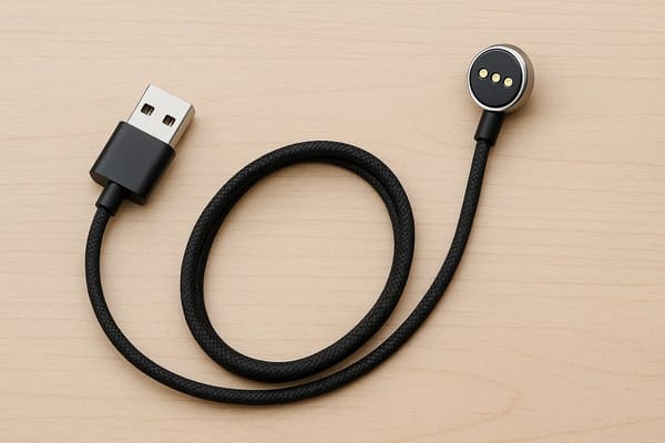
functions, but the Pin Map and mechanical module boundary should be
designed together.
Why This Trend Matters More Than Connector Miniaturization Alone
Product teams often describe magnetic pogo pin connectors as
“space-saving.”

That is only part of the story.

The larger architectural value is that a removable contact surface can be
placed differently from a deep insertion connector.

This gives industrial and mechanical designers more freedom to decide:- where the module separates;
- which side carries spring contacts;
- which side carries flat targets;
- where the magnets sit;
- where mechanical datums are located;
- which component becomes the replaceable wear item.
In other words, the adoption driver is often
architecture flexibility, not simply connector diameter.
Trend 2: Automated Systems Need a Connector That Participates in the Docking Sequence
Another important demand driver is the expansion of equipment that docks,
charges or exchanges modules without a person manually inserting a plug.
This can include:
- mobile robots;
- automated guided vehicles;
- warehouse equipment;
- inspection robots;
- autonomous charging stations;
- automatic tool changers;
- battery-swap equipment.
These systems create a fundamentally different connector requirement.

The connector is no longer simply “plugged in.”

It becomes one step in a docking state machine.
A Typical Automated Connection Has Multiple States
A simplified architecture may look like:


    System Approaches
    →
    Coarse Positioning
    →
    Mechanical Guidance
    →
    Magnetic Capture
    →
    Final Seating
    →
    Pogo Pin Compression
    →
    Connection Detection
    →
    Electrical Validation
    →
    Power / Signal Enable


Each stage solves a different problem.| Stage | Main Function |
|---|---|
| Coarse Positioning | Moves the system into the docking region |
| Mechanical Guidance | Reduces X-Y and angular error |
| Magnetic Capture | Assists final approach where required |
| Mechanical Stop | Defines final position |
| Pogo Compression | Creates the intended electrical contact state |
| Detection | Confirms required connection conditions |
| Power Enable | Activates the system after validation |
Magnetic Capture Does Not Replace Robotics or Mechanical Guidance
Magnetic attraction can assist the last portion of the approach.

It should not be expected to correct large docking errors generated by the
robot, vehicle or mechanical system.

A robust automated interface typically lets:- robotics handle gross positioning;
- mechanical features handle final alignment;
- magnets assist capture;
- pogo pins provide electrical compliance.
This separation of functions is one reason spring-contact architectures can
fit automated systems well when designed correctly.
Connection State Is Becoming as Important as the Contact Itself
Automated equipment also creates a requirement that is less important in a
simple manual plug:


    The controller needs to know whether the interface is actually ready.


Magnetic attraction alone cannot answer that question.

A connector can be:- magnetically attached but tilted;
- partially compressed;
- blocked by debris;
- missing one required contact;
- mechanically seated but electrically invalid.
This creates demand for deliberate detection and power-sequencing
architectures.
A Pilot Contact Is Information, Not Protection by Itself
A staggered or pilot contact can be used to indicate connection state.

However, it does not physically eliminate electrical arcing or unsafe
partial contact.

The control electronics must use that state information to enable or
disable the required power path.
Trend 3: Products Are Moving from Connector Selection to Interface Platforms
Another important market driver is platform development.

Many manufacturers no longer design one isolated product.

They design a family of:- devices;
- chargers;
- docks;
- accessories;
- battery modules;
- service tools.
A custom magnetic interface can become a common connection platform across
that product family.
One Physical Interface Can Support Several Product Variants
A platform may intentionally standardize:- connector outline;
- magnetic polarity;
- mating direction;
- mechanical datum position;
- common power contacts;
- common ground contacts;
- selected identification or signal positions.
Individual products can then use different subsets of the defined interface
where appropriate.

This creates a different sourcing and engineering model from selecting a
completely different connector for every device.
Platform Compatibility Must Be Designed, Not Assumed
A shared magnetic shape does not automatically create a safe product
ecosystem.

Mechanical compatibility and electrical compatibility are different.

Two devices may physically attach while having:- different voltages;
- different contact functions;
- different allowable currents;
- different control logic;
- different data requirements.
A platform interface can therefore require:- mechanical coding;
- magnetic polarity coding;
- asymmetric Pin Maps;
- device identification;
- power gating;
- software-level validation.
This is one reason custom connector development increasingly overlaps with
product-system architecture.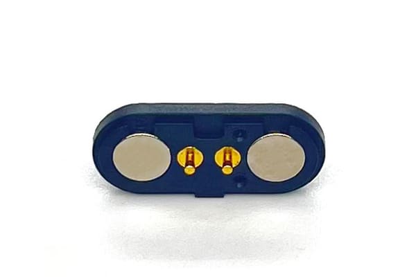
the complete product platform, including electrical compatibility,
retention and exposed-contact behavior.
Standardization Creates Value — But Also Creates Lock-In
Developing a proprietary connector platform can reduce variation across a
product family, but it also introduces trade-offs.| Potential Benefit | Potential Trade-Off |
|---|---|
| Shared cable / dock architecture | Less compatibility with third-party accessories |
| Common mechanical interface | Platform geometry becomes harder to change later |
| Custom Pin Map | Requires interface governance across product teams |
| Common service parts | Supplier and tooling dependence can increase |
| Integrated user experience | More up-front engineering is required |
The market opportunity for custom magnetic connectors therefore grows
together with product-platform complexity—but so does the need for interface
governance.
Trend 4: Serviceability Is Becoming a Design Requirement, Not an Afterthought
Connector selection is also being influenced by how products are repaired,
maintained and upgraded.

In many systems, the highest-cost component should not be the component that
wears first.

This creates a useful engineering question:


    Which side of the interface should be replaceable?


A removable contact architecture can allow designers to place the expected
wear on:- a cable assembly;
- a charging dock;
- a replaceable contact module;
- a service-side interface;
- a low-cost mating target.
rather than on the main product PCB or expensive electronics assembly.Service Architecture Changes Connector Value
Consider two products using the same connector.

In Product A, the connector is permanently buried inside the enclosure and
is never accessed after assembly.

In Product B, the interface is connected every day and the contact module
can be replaced independently.

The value of a removable spring-contact architecture is much higher in the
second case.

This is why connector selection should be linked to:- expected mating frequency;
- service interval;
- replacement cost;
- repair access;
- downtime requirements;
- which component is intended to wear first.
Lifecycle Is Moving from a Component Number to a System Maintenance Metric
A nominal mating-cycle number is useful only when the test condition matches
the real interface.

For service-driven equipment, engineers may gain more value by monitoring:- contact resistance trend;
- temperature rise;
- docking retries;
- connection validation failures;
- contact contamination;
- target wear;
- maintenance intervals.
This moves the engineering conversation from:

“How many cycles does the connector have?”
to:
    “How will the complete interface behave, degrade and be serviced during
    the product lifecycle?”
Why Medical, Robotics and Mobility Applications Keep Appearing in Market Discussions
Certain industries appear repeatedly in magnetic pogo pin discussions not
because one connector technology automatically meets their requirements,
but because their product architectures often include removable or docked
modules.
Medical and Healthcare Equipment
Potential demand can come from:- removable charging interfaces;
- sensor modules;
- wearable devices;
- accessory docks;
- service interfaces.
However, medical suitability still depends on patient contact, cleaning,
electrical safety and device-specific validation.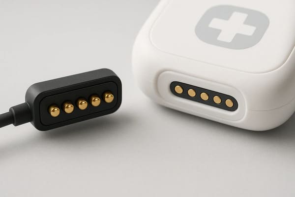
interfaces, but the connector itself does not establish sterilization,
biological safety or medical-device compliance.
Robotics and Automated Equipment
Potential demand is often driven by:- automatic charging;
- tool exchange;
- mobile robot docking;
- replaceable sensor or battery modules;
- high-frequency service operations.
Portable and Mobility Electronics
Potential demand can come from:- frequent charging;
- breakaway cable requirements;
- compact docking surfaces;
- product-family accessory systems;
- removable electronic modules.
The common factor is therefore not the industry itself.

It is the presence of a
frequently removable electrical and mechanical boundary.
Data Growth Is Not Automatically a Magnetic Connector Market Driver
Claims around 5G, high-speed data or AI hardware should be treated
carefully.

Increasing data requirements do not automatically make magnetic pogo pin
connectors preferable.

In fact, higher-speed channels can make the connector problem more
difficult.
High-speed performance can depend on:
- signal and return allocation;
- contact geometry;
- contact pitch;
- PCB transitions;
- cable structure;
- reference-plane continuity;
- crosstalk;
- complete channel length.
Therefore:


    More pins or a shorter contact does not automatically mean 5G, RF or
    high-speed protocol capability.
A Metal Housing Does Not Automatically Solve EMI
The original article described conductive connector housings as forming a
Faraday cage.

That is too broad.

A conductive housing can contribute to shielding only when the complete
grounding and shielding architecture is deliberately designed.
EMC performance can depend on:
- housing continuity;
- gaps and apertures;
- ground termination;
- signal return paths;
- PCB reference planes;
- cable shields;
- system grounding.
A metal connector body should therefore not be described as an
“impenetrable Faraday cage.”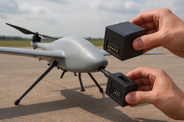
interfaces, but high-speed signal and EMC performance must be validated
through the complete electrical system.
Power Density Is Also a System Requirement
Growth in battery-powered products can increase demand for compact charging
interfaces, but this does not mean pogo pins automatically support higher
charging power.

The complete path may include:


    Power Source
    →
    PCB / Cable
    →
    Termination
    →
    Pogo Pin
    →
    Mating Interface
    →
    Target
    →
    Device


Engineers should evaluate:- complete-path resistance;
- voltage drop;
- temperature rise;
- working stroke;
- parallel-contact current sharing;
- duty cycle;
- ambient temperature.
Market demand for compact charging therefore creates an engineering
requirement rather than automatically proving connector suitability.
Why Magnetic Pogo Pin Connectors Will Not Replace Every Legacy Port
Market expansion should not be interpreted as universal replacement.

Standard connectors remain extremely strong solutions when they provide
capabilities that the application values more highly.| Requirement | Architecture Often Worth Considering |
|---|---|
| Universal Third-Party Compatibility | Standardized connector |
| Permanent Harness Connection | Locked wire connector |
| Very High Contact Density | Dedicated board-to-board connector |
| Standardized High-Speed Interface | Validated standard connector architecture |
| Frequent Blind Docking | Magnetic pogo pin worth evaluating |
| Removable Module | Magnetic or non-magnetic pogo interface worth evaluating |
| Controlled Breakaway | Magnetic interface may be advantageous |
| Automated Charging | Spring-contact docking architecture worth evaluating |
The Real Market Question: Where Does the Interface Need to Be Removable?
A useful way to evaluate the market is not to ask:


    “Which industries will use magnetic pogo pins?”
Instead ask:
    “Which products are creating new removable electrical boundaries?”


This question is more durable than a market-size forecast because it points
directly to the system requirement.
Engineering Adoption Matrix
| Requirement | Why It Drives Adoption | Main Validation Need |
|---|---|---|
| Frequent Mating | Creates demand for a serviceable contact architecture | Lifecycle and wear |
| Blind Docking | Creates demand for assisted mating | Alignment and final seating |
| Automated Charging | Requires unattended electrical connection | Connection detection and sequencing |
| Modular Hardware | Creates removable subsystem boundaries | Mechanical and electrical interface contract |
| Product Platform | Encourages shared connector architecture | Compatibility and Pin Map governance |
| Serviceability | Moves wear to replaceable components | Maintenance and replacement strategy |
| Compact External Interface | Changes how the connector fits the enclosure | Complete 3D packaging |
Questions Engineers Should Ask Before Following the Market Trend
Technology adoption should follow product requirements rather than market
momentum alone.
Before selecting a magnetic pogo pin architecture, define:
- How often will the interface mate?
- Is the connection manual or automated?
- Does the module need blind docking?
- What happens if the connection is lost?
- Does the product require universal compatibility?
- What power crosses the interface?
- What signals cross the interface?
- How is complete seating detected?
- What environment is the unmated connector exposed to?
- Which component should be replaceable?
- How will the platform evolve across future products?
Information Required for a Custom Magnetic Interface Review
| Project Input | Information to Provide |
|---|---|
| Product Architecture | Main device, removable module, cable, dock or accessory relationship |
| Mating Frequency | Expected connection profile |
| Automation | Manual, robotic or automatic docking |
| Available Space | X, Y and Z interface envelope |
| Pin Map | Power, return, detection, ID and signal functions |
| Electrical Conditions | Voltage, continuous current and peak current |
| Signal Requirements | Required control or communication interfaces |
| Mechanical Alignment | X-Y-Z and angular mating tolerance |
| Retention / Release | Desired normal holding and separation behavior |
| Environment | Temperature, moisture, dust, chemicals and metallic debris |
| Service Strategy | Which contact or module should be replaceable? |
| Platform Requirement | Whether several products should share the same interface |
Frequently Asked Questions
Why is the magnetic pogo pin connector market growing?
Adoption is being supported by products that require more removable
modules, automatic docking, frequent charging, serviceable interfaces and
product-specific connector architectures. The strength of these drivers
varies by application.
Will magnetic pogo pin connectors replace USB connectors?
Not universally. USB remains valuable for standardized interoperability.
Magnetic pogo pin interfaces are more attractive when the product benefits
from custom mating geometry, frequent removable connection, blind docking
or controlled breakaway.
Are magnetic pogo pin connectors mainly used because they are smaller?
No. Packaging can be an advantage, but modularity, docking workflow,
serviceability and product-platform integration are often equally important
reasons to evaluate the architecture.
Are magnetic pogo pins automatically suitable for high-speed data?
No. Data capability depends on contact arrangement, return paths, PCB
transitions, cable design and complete-channel validation.
Does a metal magnetic connector housing eliminate EMI?
No. Conductive housing can contribute to shielding, but EMC performance
depends on grounding, apertures, return paths, PCB layout and the complete
system.
Are magnetic pogo pin connectors automatically suitable for medical devices?
No. Medical suitability depends on the intended device, patient-contact
conditions, cleaning, electrical requirements and project-specific
validation.
Why are pogo pins useful for automated docking?
Their spring compliance can support a controlled final electrical contact
after the docking system has mechanically positioned the module. Magnets may
assist capture, but mechanical guidance and connection validation remain
necessary.
Can one magnetic connector platform be used across multiple products?
Yes, if the mechanical interface, Pin Map, voltage, power logic and
compatibility rules are intentionally standardized across the product
family.
Are magnetic pogo pin connectors better for serviceability?
They can be useful when the interface is removed frequently or when the
designer wants the replaceable contact to be separated from a more expensive
electronic module.
What is the strongest market use case for magnetic pogo pin connectors?
There is no single industry answer. The strongest use cases typically occur
where the electrical connection is also a frequently removable mechanical
boundary, such as docking, charging, accessories, replaceable modules or
service interfaces.
What information is needed to design a custom magnetic pogo pin connector?
Define the product architecture, mating frequency, Pin Map, voltage,
current, signal requirements, available space, docking tolerance, retention,
environment, lifecycle and service strategy.
Request a Magnetic Pogo Pin Interface Engineering Review
Explore

    custom magnetic connector solutions

for removable charging, docking and modular product interfaces.

Review

    pogo pin and spring-contact solutions

for project-specific contact layouts and mounting structures.

Learn more about CTP engineering and manufacturing capabilities on the

    About Us page
.

Submit your product architecture, Pin Map, electrical requirements,
available space, mating direction and mechanical drawings through the

    Get Quote & Samples page
.


    CTP can review pogo pin contact layouts, magnetic capture, mechanical
    datums, working stroke, Pin Maps, module boundaries and PCB, FPC, wire
    or cable termination for custom removable connector architectures.
    Final current capability, signal performance, lifecycle, environmental
    protection and system reliability depend on the approved design and
    project-specific validation.
CTP ENGINEERING PATHS
Choose the right path for your project
Move from application requirements to a connector pair, a data-capable cable assembly, or a charging cable configuration. Final specifications are confirmed against an approved drawing and project validation plan.
01
Magnetic Connectors
Connector geometry, pin layout, mechanical integration and OEM/ODM review.
Engineering overview → 02Magnetic Data Cables
Power and signal allocation, cable exit, interface selection and assembly review.
Cable engineering → 03Magnetic Charging Cables
Browse the complete cable catalog and shortlist a starting structure for customization.
View cable catalog →