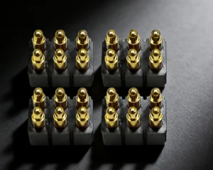
Pogo pin material selection should be defined as a complete material and plating stack. Engineers should specify the plunger, barrel, spring, termination and mating-pad materials separately, then connect each selection to working stroke, contact force, current, wear, environment and manufacturing process. No single alloy or plating system is optimal for every pogo pin connector.
A pogo pin should not be specified only as “beryllium copper with gold plating.” A spring-loaded contact normally contains several components, and each component performs a different electrical, mechanical or manufacturing function.
The plunger must provide a controlled contact surface. The spring must maintain force through the approved working stroke. The barrel or base must guide the plunger and connect the current path to the PCB or wire termination. The plating stack must support the required contact behavior while remaining compatible with the base material, mating pad and assembly process.
This guide explains how engineers can specify pogo pin materials and plating without assuming that one alloy, one gold thickness or one supplier construction is universally superior.
What Materials Are Used in a Pogo Pin?
A pogo pin is an assembly rather than one solid material. Depending on the construction, the main elements may include:
- Plunger or contact piston
- Barrel, shell or base
- Internal spring
- Rear termination
- PCB mounting feature
- Contact finish
- Nickel or another underplate
- Housing or insulating carrier
- Flat mating pad or target contact
Each element may use a different material or plating finish. The material specification should therefore identify the exact component to which each requirement applies.
For example, the following statements have very different meanings:
- Gold finish on the plunger contact area
- Gold over nickel on all external conductive surfaces
- Gold finish on the mating area and tin on the solder termination
- Gold-plated copper-alloy piston with a separately plated spring
A drawing that simply states “gold-plated pogo pin” does not provide enough information for engineering comparison or production control.
There Is No Universal Best Pogo Pin Material
The correct material system depends on the actual application.
A factory test probe may prioritize high mating frequency and replaceability. A wearable charging connector may prioritize compact size, sweat exposure and user touch. A high-current power interface may prioritize voltage drop and temperature rise. A service connector may prioritize solderability and dimensional repeatability.
The material decision should be based on:
- Electrical current and voltage
- Signal type and data requirement
- Contact force
- Working stroke
- Expected mating frequency
- Mating-pad material and finish
- Sliding or wiping movement
- Operating temperature
- Humidity, condensation and contamination
- Cleaning chemicals
- PCB or wire termination method
- Reflow, soldering or assembly temperature
- Cost and production-volume requirements
The objective is not to select the most expensive alloy. The objective is to create a controlled material stack that meets the electrical, mechanical and environmental requirements of the complete connector.
Begin with the Application Requirements
Before specifying any alloy or plating, convert the device requirement into measurable engineering inputs.
| Application Input | Engineering Question | Material Impact |
|---|---|---|
| Electrical load | What voltage, current and duty cycle must pass through each contact? | Base conductivity, plating system, termination and thermal path |
| Contact movement | Is the mating motion axial, sliding, wiping or angular? | Contact finish, tip geometry and wear mechanism |
| Working stroke | What are the minimum, nominal and maximum compression positions? | Spring design, spring material and force retention |
| Service life | How many mating operations are expected in the application? | Wear allowance, plating specification and validation scope |
| Environment | Will the connector encounter moisture, sweat, salt, dust or chemicals? | Base-material protection, coating compatibility and sealing strategy |
| Assembly process | Will the contact be reflowed, hand-soldered, crimped, welded or press-fitted? | Termination finish, material stability and process limits |
| Mating pad | What material and finish will contact the pogo pin tip? | Wear pairing, contact resistance and corrosion compatibility |
Unknown inputs should remain open engineering items. They should not be silently replaced with a standard gold thickness or a default spring material.
Plunger Material Selection
The plunger is the moving contact element that touches the mating pad. It must combine dimensional accuracy, surface-finish compatibility, mechanical support and an acceptable electrical path.
Common engineering considerations include:
- Machinability for small diameters and detailed tip geometries
- Strength under axial and unintended lateral loading
- Compatibility with the selected underplate and contact finish
- Surface quality before plating
- Electrical contribution to the complete contact path
- Wear behavior against the target pad
- Dimensional stability during production
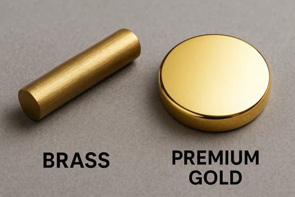
Brass and Other Copper Alloys
Machined copper alloys, including brass-based materials, are used in commercial spring-loaded contacts because they can support precision machining and subsequent plating.
Brass should not automatically be classified as an inferior pogo pin material. Its suitability depends on:
- The exact alloy
- Plunger dimensions
- Mechanical load
- Plating stack
- Operating environment
- Expected wear
An exposed brass surface may tarnish in some environments, but a finished pogo pin is normally evaluated as a plated contact system. The base alloy and the protective finish should therefore be considered together.
Beryllium Copper Plungers
Beryllium copper may be considered where the design requires a copper alloy with a particular combination of mechanical and electrical properties.
However, selecting beryllium copper for the plunger does not automatically guarantee:
- Lower contact resistance
- Longer cycle life
- Higher current capability
- Better corrosion resistance
- Improved signal integrity
Those results also depend on the contact finish, plunger geometry, spring force, mating pad, working stroke and complete connector structure.
Stainless Steel Plungers
Stainless-steel components may be considered for specific mechanical or environmental requirements, but their electrical and plating implications must be reviewed.
The engineering team should confirm:
- Whether the stainless-steel grade is suitable for the intended machining process
- How the plating system bonds to the substrate
- Whether the electrical path remains within the project limits
- Whether the plunger is expected to carry the full operating current
Material selection should be based on the complete contact architecture, not on corrosion resistance or strength alone.
Plunger Tip Geometry Is Part of the Material System
The same material and plating can behave differently when used on different tip geometries.
Common tip concepts include:
- Flat tip
- Rounded tip
- Conical tip
- Crown tip
- Serrated or multi-point tip
- Custom shaped contact surface
Tip geometry influences:
- Contact area
- Local contact pressure
- Ability to move through light surface contamination
- Pad indentation
- Sliding and wiping behavior
- Finish wear
- Generation of wear debris
A sharp or crown-shaped tip may concentrate force over a smaller area. A flat or rounded tip may distribute force differently. Neither design is universally superior.
The selected tip should be evaluated with the actual:
- Spring force
- Working stroke
- Mating-pad finish
- Alignment tolerance
- Cycle requirement
- Environmental contamination
Barrel and Base Material Selection
The barrel guides the moving plunger and may also form part of the current path and PCB or cable termination.
The barrel material should support:
- Dimensional control of the internal bore
- Plunger guidance
- Spring retention
- Mechanical retention inside the housing
- Electrical continuity to the termination
- Compatibility with the selected plating process
- Soldering, press-fit or assembly requirements
Copper alloys are commonly used in contact components, but the exact alloy should be selected from the mechanical, electrical and manufacturing requirements.
The barrel should not be treated only as a passive housing. Its internal surface condition, bore tolerance and relationship with the plunger can affect:
- Plunger movement
- Internal resistance
- Friction
- Return behavior
- Sensitivity to particles
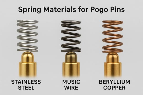
Spring Material Selection
The internal spring maintains contact force as the plunger moves through the approved working range.
Spring material selection should consider:
- Required force at defined stroke positions
- Available spring volume
- Maximum permitted stress
- Expected compression frequency
- Operating and assembly temperature
- Force stability after cycling
- Corrosion exposure inside the barrel
- Electrical role of the spring
Beryllium Copper Springs
Beryllium copper is used in some commercial spring-loaded contact constructions. It may provide a useful combination of spring behavior and conductivity for a specific design.
It should not be assumed that every high-cycle pogo pin requires a beryllium-copper spring. The result also depends on:
- Spring-wire dimensions
- Coil geometry
- Heat treatment
- Working stroke
- Compression speed
- Operating temperature
- Production variation
Stainless Steel Springs
Stainless-steel springs are also used in some spring-loaded contact constructions. Their suitability depends on the mechanical, thermal and electrical architecture of the individual pin.
Where the spring forms part of the electrical path, engineers should review the complete pin resistance rather than comparing spring-material conductivity in isolation.
The Spring Material Is Only One Part of Force Retention
Force retention cannot be predicted from the alloy name alone.
The approved specification should include:
- Free height
- Total travel
- Working-stroke range
- Spring force at defined positions
- Force tolerance
- Maximum permitted compression
- Return-height requirement
- Post-conditioning force requirement where applicable
Material identity without the spring geometry and force-stroke limits is not sufficient for engineering approval.
Understand the Complete Plating Stack
A contact finish may contain several layers.
A simplified stack may be:
- Base material
- Surface preparation
- Nickel or another underplate
- Final contact finish
Different surfaces on the same pogo pin may use different finishes. For example:
- Gold-based finish on the mating contact area
- Gold or tin-based finish on the PCB termination
- Separate finish on the internal spring
- Different plating thicknesses on selected surfaces
The drawing should state whether the plating requirement applies to:
- The entire plunger
- The plunger contact area only
- The barrel exterior
- The barrel interior
- The PCB termination
- The spring
- All conductive components
What Does the Nickel Underplate Do?
Gold-over-nickel systems are widely used in connector products. The nickel layer may support several functions within the complete plating system.
Depending on the process and base material, the underplate may help:
- Separate the contact finish from the base alloy
- Create a controlled substrate for the final finish
- Reduce migration between layers
- Support wear behavior
- Improve consistency of the finished surface
The nickel requirement should not be omitted merely because the final visible surface is gold.
The engineering specification should identify:
- Underplate material
- Required thickness or approved range
- Surfaces covered
- Exceptions at solder or assembly interfaces
- Inspection or verification method
Gold Plating Is Not a Zero-Resistance Guarantee
Gold-based finishes are often selected for electrical contact surfaces, but the presence of gold does not create zero contact resistance.
Measured resistance still depends on:
- Contact force
- Actual contact area
- Tip geometry
- Mating-pad finish
- Surface cleanliness
- Base and underplate condition
- Wear
- Internal pogo pin construction
- Measurement points
- Test current and method
IEC 60512-2-1 and IEC 60512-2-2 provide connector contact-resistance measurement methods. The project must still define the measuring points, sample condition and acceptance limit.
A technical drawing should use measurable wording such as:
- Contact resistance across the complete mated interface
- Resistance measured at a defined test current
- Maximum permitted initial resistance
- Maximum permitted resistance change after conditioning
It should not rely on phrases such as:
- Zero resistance
- Perfect conductivity
- Guaranteed signal transmission
- Permanent corrosion protection
Gold Thickness Should Be Connected to the Application
Specifying “thick gold” without a value, surface area or test requirement is not an engineering specification.
The required finish should be linked to:
- Expected contact motion
- Contact force
- Tip geometry
- Mating-pad finish
- Cycle requirement
- Environmental exposure
- Cost target
- Verification method
A thicker final finish does not automatically correct:
- Rough or defective base material
- Inadequate underplate
- Excessive sliding
- Incorrect working stroke
- Sharp edge loading
- Contamination
- Misalignment
The plating system and contact mechanics should be developed together.
Palladium-Nickel and Alternative Contact Finishes
Some connector products use palladium-nickel systems with a gold flash or related finish architecture.
Such a finish may be considered when it is compatible with the contact geometry, wear requirement, mating surface and production process.
It should not be substituted for gold-over-nickel solely to reduce cost without reviewing:
- Contact resistance
- Contact force
- Wear mechanism
- Mating-pad compatibility
- Environmental exposure
- Manufacturing capability
- Customer specification
A supplier should identify the exact finish stack rather than using a general description such as “premium plating.”
Contact Finish and Termination Finish May Be Different
The best finish for a repeatedly mated electrical surface may not be the same as the best finish for a solder or crimp termination.
Commercial connector products may use:
- Gold on the mating area
- Tin over nickel on the termination area
- Gold on both mating and termination areas
- Selective plating on functional surfaces
Selective finishing can help align the surface treatment with the function of each area.
The drawing should distinguish:
| Surface | Primary Function | Specification Question |
|---|---|---|
| Plunger tip | Repeated electrical contact | What finish and thickness are required in the wear area? |
| Barrel exterior | Mechanical retention and possible electrical path | Does the surface require full or selective plating? |
| PCB tail | Soldering or press-fit connection | What finish is compatible with the assembly process? |
| Wire termination | Crimp, weld or solder connection | What surface treatment is required for the termination method? |
| Internal spring | Mechanical force and possible current path | Does it require plating, and what function does that plating serve? |
The Mating Pad Must Be Specified with the Pogo Pin
A pogo pin contact surface cannot be evaluated independently from its mating pad.
The mating pad specification should include:
- Base material
- Underplate
- Final contact finish
- Pad dimensions
- Pad thickness or PCB construction
- Surface flatness
- Position tolerance
- Permitted wear area
- Cleaning and contamination requirements
Harwin and Mill-Max both publish flat target contacts intended to mate with spring-loaded contacts, including gold-finished target surfaces. These examples demonstrate that the target pad is a defined connector component rather than an arbitrary exposed copper area.
Avoid Uncontrolled Finish Pairings
The engineering team should verify the compatibility of the pogo pin finish and the target-pad finish.
Potential problems include:
- Unequal wear between hard and soft surfaces
- Transfer of material between mating surfaces
- Exposure of an underlying layer
- Corrosion after the finish is damaged
- Inconsistent resistance between prototype and mass production
Changing the PCB finish or target-pad supplier can change the contact interface even when the pogo pin part number remains unchanged.
Base Material, Plating and Contact Force Must Be Reviewed Together
Material selection cannot be separated from the mechanical contact design.
The same plated plunger can perform differently under:
- Different spring forces
- Different working strokes
- Different tip geometries
- Different pad sizes
- Different amounts of sliding
- Different environmental exposure
Low contact force may produce unstable contact under movement or contamination. Excessive force may increase pad indentation, finish wear, housing load and PCB deflection.
The design should establish a controlled operating window containing:
- Minimum contact force
- Nominal contact force
- Maximum contact force
- Minimum working stroke
- Nominal working stroke
- Maximum working stroke
- Approved pad and finish combination
Material Selection for Power Contacts
For power contacts, the material system should be evaluated as part of the complete current path.
The current path may include:
- Plunger
- Plunger-to-barrel interface
- Internal spring or alternate current path
- Barrel and rear termination
- Contact interface
- Mating pad
- PCB trace
- Wire or cable termination
The engineering review should include:
- Initial contact resistance
- Voltage drop under the specified current
- Temperature rise after stabilization
- Performance at minimum working stroke
- Current distribution between parallel contacts
- Resistance change after environmental or mechanical conditioning
High-conductivity material in one component does not compensate for excessive resistance elsewhere in the assembly.
Material Selection for Signal Contacts
Signal contacts may carry less current than power contacts, but they can be sensitive to resistance instability, contact bounce and contamination.
The design should define:
- Signal type
- Voltage level
- Data rate
- Ground return
- Permitted resistance variation
- Contact sequence
- Environmental condition
- Dynamic movement during operation
A gold-colored surface does not establish high-speed data capability. Signal performance also depends on:
- Pin layout
- Spacing
- Return path
- Channel impedance
- Cable construction
- PCB routing
- Shielding
Material and plating are part of the signal channel, but they are not the complete signal-integrity solution.
Corrosion Protection Requires a Complete Material Review
Corrosion behavior depends on more than the visible contact finish.
Review:
- Base alloy
- Underplate continuity
- Final finish
- Porosity or surface defects
- Wear through the finish
- Adjacent dissimilar metals
- Moisture retention
- Contamination introduced during assembly
- Cleaning residues
- Electrical bias while wet
Gold plating should not be described as permanently eliminating corrosion. If the surface is worn, porous, contaminated or combined with an incompatible material system, corrosion-related degradation may still occur.
Galvanic Corrosion Requires an Electrical and Environmental Path
Galvanic behavior depends on the combination of dissimilar materials, electrical connection and an electrolyte.
The design review should therefore consider:
- Contact and mating-pad materials
- Magnet coating
- Housing inserts
- PCB finish
- Exposed cable or termination metals
- Expected moisture or chemical exposure
Changing one material can affect the complete assembly, especially after wear exposes an underlying layer.
Magnetic Connector Materials Require Additional Review
In a magnetic pogo pin connector, the contact materials operate near magnets, housings, adhesives and possible steel return paths.
The review should include:
- Magnet material and coating
- Adhesive or mechanical magnet retention
- Housing resin
- Steel or magnetic return component
- Air gap
- Exposure to metallic debris
- Potential galvanic combinations
- Assembly and curing temperature
The magnet grade does not determine pogo pin material performance. A stronger magnet cannot correct an unsuitable contact finish, incorrect working stroke or incompatible target pad.
Housing Material Affects the Contact Interface
The insulating carrier or housing controls the relative position of the pogo pins.
Housing-material behavior can affect:
- Pin position
- Connector flatness
- Working stroke
- Magnetic air gap
- Seal compression
- PCB load
- Temperature-related dimensional change
A stable metal contact system can still produce poor electrical results if the housing allows uneven pin compression or excessive movement.
The material specification should therefore include the connector housing and not only the conductive elements.
Assembly Temperature and Soldering Compatibility
A pogo pin selected for SMT reflow must be reviewed differently from a pin that is hand-soldered, press-fitted, crimped or welded.
Define:
- Peak assembly temperature
- Time at temperature
- Number of thermal cycles
- PCB finish
- Solder alloy and flux
- Cleaning process
- Plastic or pick-and-place cap requirements
- Post-reflow dimensional and force requirements
A commercial pogo pin material declaration may state a specific peak reflow condition for that product. Such a value should not automatically be transferred to another pin construction.
Avoid Solder and Flux Entering the Moving Interface
The design and process should control:
- Solder wicking
- Flux migration
- Cleaning-fluid entry
- Particles entering the barrel
- Heat transfer into the spring and internal surfaces
A pin may pass initial continuity inspection but later experience sticking if assembly residue reaches the moving interface.
Material Verification Should Match the Risk
Material and plating requirements are only useful when they can be verified.
Depending on project risk, evidence may include:
- Approved product drawing
- Material declaration
- Supplier certificate of conformity
- Base-material certificate
- Plating-process record
- Plating-thickness measurement
- Cross-sectional analysis
- Surface inspection
- Contact-resistance measurements
- Spring-force measurements
- Environmental or wear-test records
Not every shipment requires destructive material analysis. The control method should reflect:
- Application risk
- Production volume
- Supplier history
- Material-change risk
- Customer documentation requirements
What Should Be Defined on the Pogo Pin Drawing?
A complete material specification may include:
| Drawing Field | Required Definition |
|---|---|
| Plunger material | Approved alloy or controlled material specification |
| Barrel or base material | Approved alloy and applicable mechanical requirement |
| Spring material | Approved material, treatment and force-stroke requirement |
| Underplate | Material, surface coverage and thickness requirement |
| Contact finish | Material, thickness or approved range and functional surface |
| Termination finish | Finish compatible with the intended PCB or wire process |
| Plunger-tip geometry | Dimensions, radius, crown or custom profile |
| Mating-pad specification | Pad material, finish, dimensions and position tolerance |
| Working stroke | Minimum, nominal and maximum compression |
| Spring force | Permitted force at defined stroke positions |
| Electrical limit | Contact resistance, voltage drop or temperature-rise criteria |
| Assembly process | Reflow, soldering, press-fit, welding or other process limits |
Do not specify only:
- Premium alloy
- High-grade gold
- Thick plating
- Imported spring
- Low resistance
- Long service life
These phrases cannot be consistently inspected or approved.
Pogo Pin Material Selection Matrix
The following matrix provides a design-review framework. It is not a universal material recommendation.
| Application Priority | Material and Finish Questions | Required Validation |
|---|---|---|
| Repeated mechanical operation | Is the finish compatible with the tip geometry, pad and movement? | Wear, resistance change, spring force and pad inspection |
| Power transmission | Is the complete conductive path suitable for the required load? | Voltage drop, temperature rise and individual-channel resistance |
| Low-level signal | Is the finish stable under low current and limited contact movement? | Millivolt-level resistance and dynamic continuity |
| Humidity or condensation | Are the base material, underplate and mating pad protected? | Project-specific environmental conditioning and post-test inspection |
| SMT assembly | Are the housing, finish and spring construction compatible with reflow? | Reflow exposure, solderability and post-process force measurement |
| Parallel power contacts | Can plating and dimensional variation create unequal resistance? | Individual current sharing and thermal evaluation |
| Magnetic connector | Are the contact materials compatible with magnets, housing and debris risk? | Complete connector force, alignment, contamination and electrical testing |
Common Pogo Pin Material Specification Mistakes
| Specification Mistake | Possible Consequence | Better Engineering Approach |
|---|---|---|
| Calling all brass pogo pins low quality | A suitable machined and plated construction may be rejected without evidence | Evaluate the exact alloy, geometry, plating and application |
| Requiring beryllium copper for every component | Cost increases without demonstrating a project benefit | Specify materials separately for the plunger, barrel and spring |
| Writing only “gold plated” | Underplate, thickness and plated surfaces remain undefined | Specify the complete plating stack and coverage |
| Assuming thicker gold solves wear | Misalignment or excessive sliding continues to damage the interface | Control force, tip geometry, pad and mating movement |
| Ignoring the mating-pad finish | Prototype and production results become inconsistent | Approve the pin and pad as one contact pair |
| Using one finish for every surface | The solder termination may not be optimized for assembly | Separate mating-area and termination-area requirements |
| Choosing material only from conductivity | Mechanical force, plating adhesion or wear may be unsuitable | Review electrical, mechanical and process requirements together |
| Assuming gold means zero corrosion | Wear, pores or exposed base material remain unaddressed | Evaluate the complete plating and environmental system |
| Applying a material test report to another design | The report may not represent the new geometry or process | Confirm part number, revision and material equivalence |
Supplier Documentation Checklist
For a custom pogo pin project, request documentation appropriate to the application risk.
- Approved pogo pin drawing
- Plunger, barrel and spring material identification
- Complete plating stack
- Plating coverage and thickness requirements
- Spring-force and working-stroke data
- Mating-pad recommendation
- Contact-resistance measurement conditions
- Assembly-temperature limits
- Material and regulatory declarations where required
- Change-notification requirements
- Prototype and production traceability
A generic brochure stating “gold-plated beryllium copper” should not replace a controlled product drawing.
Engineering Reference Sources
The following manufacturer and standards sources illustrate how commercial connector products define base materials, underplates, finishes and electrical measurements. The exact specification must still be confirmed for the individual project.
- Harwin P70 pogo pin material declaration
- Harwin pogo pins and mating contact pads
- Mill-Max spring-loaded connector material specifications
- Mill-Max gold-over-nickel mating target discs
- TE Connectivity copper-alloy spring contact with gold over nickel
- TE Connectivity palladium-nickel and gold contact-finish example
- IEC 60512-2-1 — Contact resistance, millivolt-level method
- IEC 60512-2-2 — Contact resistance, specified-test-current method
Frequently Asked Questions
What is the best material for a pogo pin plunger?
There is no universal best material. The selection depends on the plunger geometry, mechanical load, electrical path, plating system, mating pad, environment and production process. Machined copper alloys, including brass-based materials, are used in commercial pogo pins when suitable for the complete construction.
Does every high-quality pogo pin require a beryllium-copper spring?
No. Beryllium copper is used in some spring-loaded contact designs, while other constructions may use stainless steel or another approved spring material. Spring performance depends on material, geometry, treatment, working stroke and operating conditions.
Is gold plating always required?
Not for every surface or application. Gold-based finishes are frequently used on mating contact areas, but termination surfaces may use a different finish. The finish should be selected from the electrical, wear, environmental and assembly requirements.
Does thicker gold always provide longer cycle life?
No. Finish thickness is only one factor. Contact force, tip geometry, mating-pad finish, sliding movement, surface preparation and environmental exposure also affect wear and resistance stability.
Why is nickel used under gold plating?
A nickel underplate can form part of the controlled plating system between the base alloy and final contact finish. Its specific function and thickness should be defined for the selected base material and application.
Can gold plating eliminate contact resistance?
No. Contact resistance also depends on contact force, geometry, surface condition, contamination, internal pin construction and the mating pad. It should be measured using a defined method and acceptance limit.
Should the mating pad use the same finish as the pogo pin?
The pogo pin and mating-pad finishes should be evaluated as a contact pair. They do not necessarily need identical stacks, but their wear, corrosion and electrical compatibility should be confirmed.
Can tin be used on a pogo pin?
Tin-based finishes may be used on selected termination areas in connector products. A repeatedly mated contact area has different requirements from a solder termination, so the exact plated surface must be specified.
Does beryllium copper supports one million cycles?
No. Mechanical life depends on the complete spring design, working stroke, force, mating geometry, finish, environment and test conditions. Material identity alone cannot establish a cycle-life rating.
What material information should be included in an RFQ?
Include the application, pin function, current, voltage, working stroke, contact force, mating-pad finish, expected mating frequency, environmental exposure, assembly process and required documentation. Allow the supplier to propose a controlled material stack unless the project has a mandatory material specification.
Prepare the Inputs for a Pogo Pin Material Review
Before approving the material and plating stack, provide:
- Application and device type
- Pin count and pin map
- Voltage, current and signal functions
- Plunger-tip requirement
- Working-stroke window
- Contact-force range
- Mating-pad material and finish
- Expected mating frequency
- Operating and storage temperatures
- Humidity, sweat, salt, dust or chemical exposure
- PCB, wire or cable termination method
- Reflow or soldering conditions
- Required material and plating documentation
- Applicable validation criteria
Review available custom pogo pin connector structures, access additional connector engineering guides, or submit your drawings and material requirements through the Get Quote & Samples page.
CTP can review the plunger, barrel, spring, plating stack, mating pad, working stroke and assembly process before prototype development. Final material grades, finish thicknesses, electrical limits and verification methods should be confirmed in the approved drawing and project specification.