The Ultimate Engineering Guide to Pogo Pins (2026): Types, Structure, and High-Current Design
As the global electronic supply chain shifts toward more compact, waterproof, and modular device architectures, finding a reliable interconnect solution is a top priority for hardware engineers. Enter the magnetic connector powered by precisionpogo pins—a technology that is rapidly replacing traditional plug-in ports across consumer and industrial applications.
Whether you are designing a compact wearable, a medical device, or a heavy-duty connector panel, understanding the mechanical and electrical properties of these spring-loaded contacts is crucial. This technical guide explores the exact structure, the different types of pogo pins, and the engineering principles required to achieve safe, 5A+ high-current transmission.
1. What Are Pogo Pins and How Do They Work?
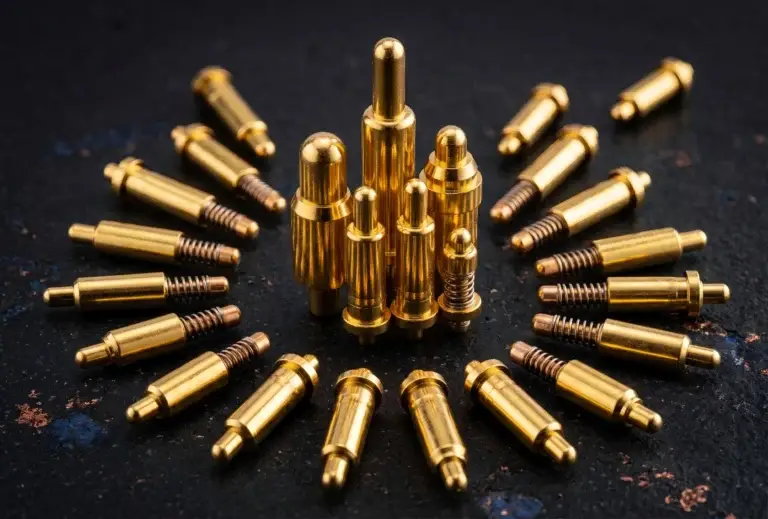
A pogo pin is a precision spring-loaded mechanism designed to create a highly reliable, temporary electrical connection. By utilizing mechanical compression between a barrel, a plunger, and a precision spring, they allow devices to pin connect seamlessly without the friction, insertion force, and wear associated with traditional plugs.
From a Single Pin to a Complete Board Connector
While standard pins often use basic alloys, high-end industrial pins require superior metallurgy to maintain conductivity. Top-tier manufacturers typically CNC-machine the plunger and barrel from Brass C6801 (recognized for exceptional machinability and electrical conductivity by the Copper Development Association), paired with a SUS304 Stainless Steel spring to guarantee a stable contact force of up to 120g.
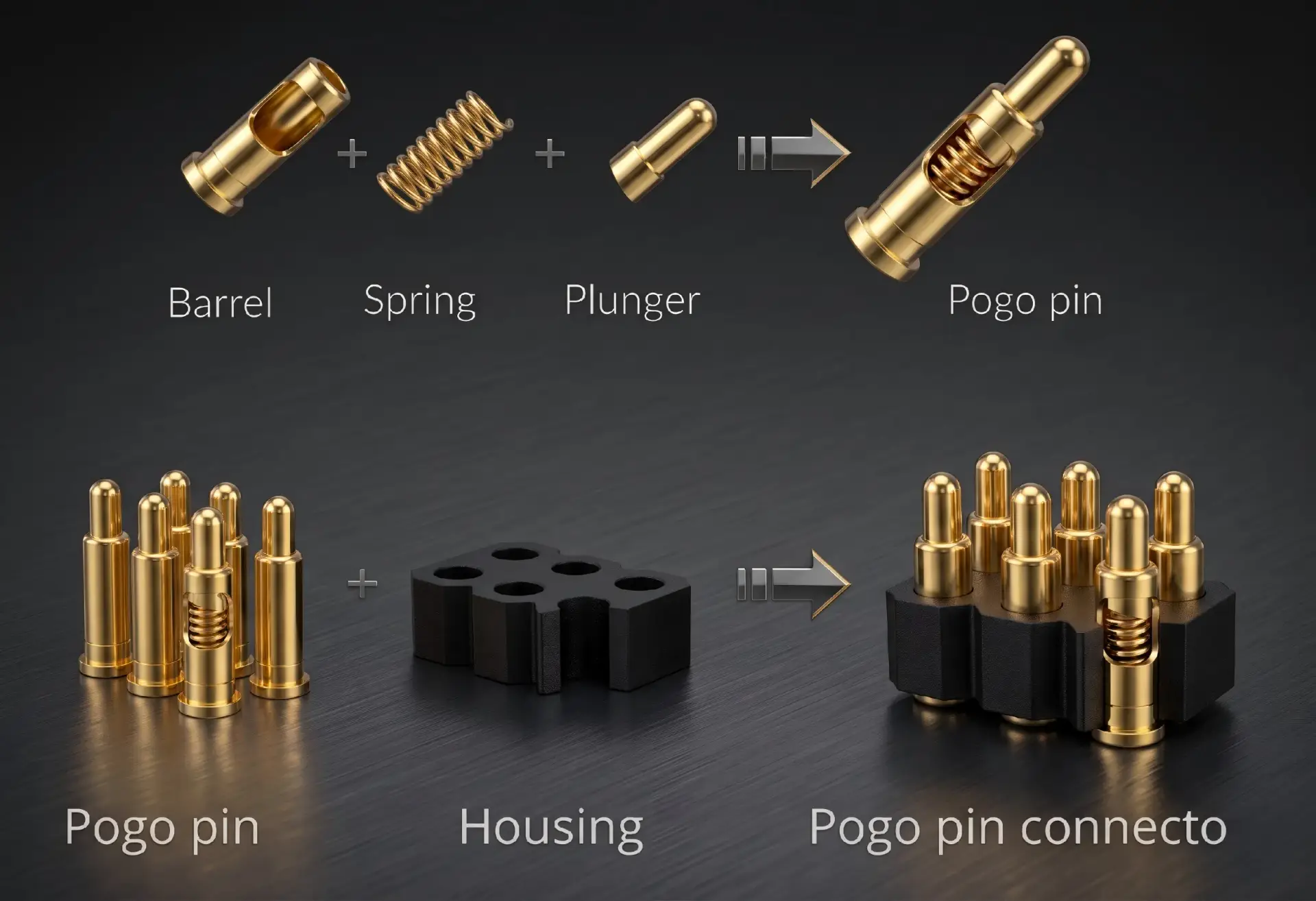
However, a single pin rarely functions alone. Multiple pins are precision-molded into a customized plastic housing alongside strong N52 magnets to form a complete magnetic connector. This modular design ensures precise alignment and prevents short circuits when integrated into a connector board.
2. Upgrading from Traditional Ports: Why Magnetic Pogo?
Many engineers historically default to searching for old-school 2 pin dc connector types or bulky 2 pin power cord types for power delivery. However, as devices become smaller, these traditional ports present significant drawbacks: susceptibility to water ingress, physical port breakage, and a limited mechanical lifespan (failing often after just 5,000 to 10,000 cycles).
Upgrading to a custom pogo pin charging solution provides unmatched engineering benefits:
- Blind Mating: Magnetic arrays guide the pins into place instantly, ensuring foolproof connections for end-users.
- Extreme Durability: Industrial-grade spring contacts are rated for up to 1,000,000 mechanical cycles.
- Space Optimization: Eliminates the need for deep internal port cavities, freeing up valuable PCB real estate for compact wearable technology.
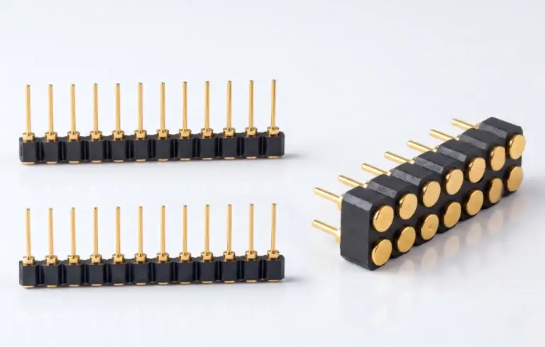
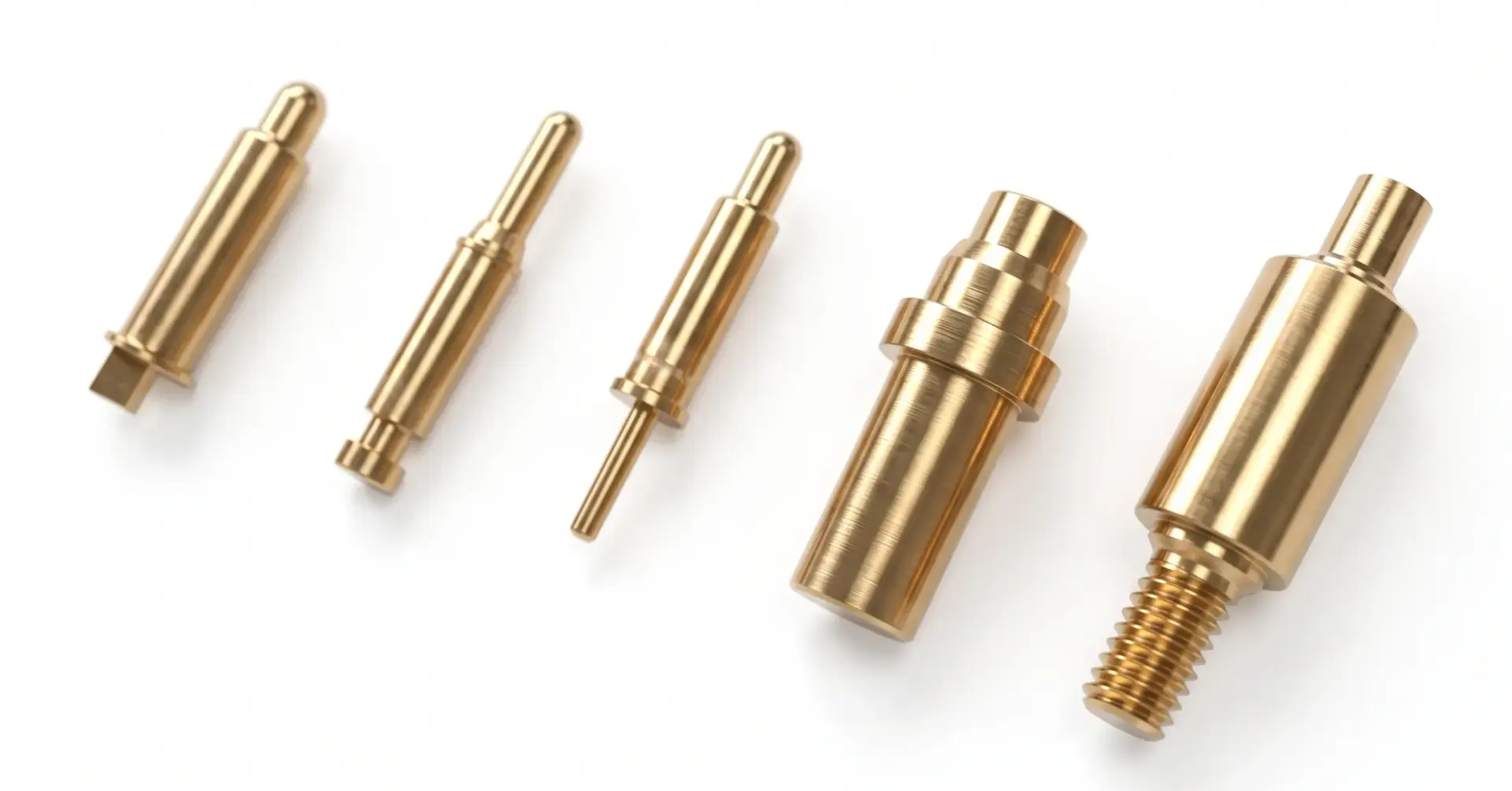
3. Common Types of Pogo Pins for PCB Integration
Depending on the PCB layout and automated assembly process, selecting the appropriate mounting style is critical. The industry standard configurations typically range from 1.27mm to 3.00mm pitch:
- SMT/SMD (Surface Mount): Features a flat base for automated pick-and-place assembly. Perfect for space-constrained devices like smartwatches and TWS earbuds.
- DIP (Through-Hole): Includes a positioning tail to provide maximum structural stability when used as a board connector on main motherboards.
- Right Angle / Bend: Designed for edge-routing layouts where vertical Z-axis space is limited.
- Solder Cup: The go-to choice for terminating wires in custom magnetic cable assemblies.
4. Overcoming High-Current & Waterproofing Challenges
Standard consumer-grade pins typically handle 1A to 2A safely. When engineers attempt to push more power (such as for fast charging) through standard pins, they often encounter Joule heating—excessive heat generation caused by high internal contact resistance, which can permanently melt plastic housings.
To safely utilize high current pogo pins, advanced internal structures (such as Bias Tail and Back Drill designs) must be employed to minimize contact resistance to under 50 mΩ. This allows the pins to safely transmit 3A, 5A, and beyond.
Furthermore, to pass rigorous salt-spray testing and meet strict IEC IP68 waterproof standards, a robust Gold over Nickel plating process is required. High-end applications often specify gold plating thicknesses up to 1.50μm to prevent galvanic corrosion.
| Technical Specification | Standard Market Pin | High-End Industrial Standard |
|---|---|---|
| Mechanical Lifespan | 10,000 – 50,000 cycles | Up to 1,000,000 cycles |
| Current Rating | 1A – 2A | 3A, 5A, and Custom High Current |
| Contact Resistance | > 100 mΩ | < 50 mΩ Max |
| Gold Plating Thickness | 0.025μm (Flash Gold) | Up to 1.50μm |
5. Frequently Asked Questions (FAQ)
Q1: Can pogo pins transmit data as well as power?
Yes. While high current pogo pins are structurally optimized for power delivery, standard designs maintain excellent signal integrity, making them highly effective for high-speed data transmission with minimal signal loss.
Q2: How do I specify a custom board connector?
When working with a professional pogo pin supplier, you can customize the pitch, working height, spring force, and gold plating thickness to ensure the component perfectly matches your connector board specifications and environmental requirements.
Technical Design Guide & Catalog 2026
Access full CAD models, high-current specifications, and precision tolerances in one complete document.