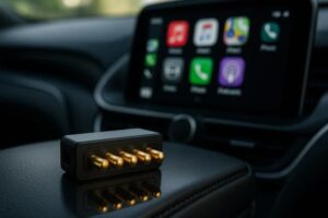
Selecting a circuit board connector begins with the connection boundary: board-to-board, wire-to-board, module-to-device or cable-to-device. Rigid PCB connectors are normally used for controlled internal assemblies, pogo pin connectors add spring compliance for repeated or tolerance-sensitive contact, and magnetic charging connectors add magnet-assisted capture for detachable external interfaces. The correct choice depends on alignment, retention, mating frequency, electrical functions, environmental exposure and production method.
A connector should not be selected only by Pin count, current rating or external appearance.
Engineers first need to define what is being connected, how the two parts approach each other, whether the interface is permanent or detachable, and which mechanical structure controls the final mating position.
Modern electronic products may contain several connector architectures in the same system. A product can use a board-to-board connector internally, an FPC connector between modules, a pogo pin connector for a removable battery, and a magnetic charging interface on the external enclosure.
This guide compares common circuit board connector architectures and explains when a
pogo pin connector
or
magnetic connector
may be more suitable than a conventional rigid plug.What Is a Circuit Board Connector?
A circuit board connector creates an electrical path between a PCB and another board, cable, module, battery, device or external accessory.The complete interface may include:
- Conductive contacts
- An insulating housing
- PCB, wire, FPC or cable termination
- Mechanical alignment features
- A retention or release mechanism
- A mating connector or conductive target
- Sealing structures where environmental protection is required
The connector contacts carry the electrical functions, but the housing and surrounding device structure normally determine alignment, compression, retention and mechanical protection.Start by Defining the Connection Boundary
Connector selection becomes easier when the project is first classified by what the interface must connect.| Connection Boundary | Common Architecture | Typical Design Priority |
|---|---|---|
| PCB to PCB | Board-to-board or mezzanine connector | Board spacing, Pin count, routing and assembly tolerance |
| Wire harness to PCB | Wire-to-board connector | Wire size, locking, serviceability and strain relief |
| FPC or flexible circuit to PCB | FFC/FPC connector | Low profile, pitch, insertion process and bend control |
| Removable module to device | Card-edge, blade or pogo pin connector | Repeated mating, tolerance and replacement access |
| Dock or cradle to device | Pogo pin connector | Contact compliance, alignment and target-pad design |
| Charging cable to external device | Magnetic charging connector | Capture, release, polarity, sealing and user interaction |
| Production fixture to PCB | Test probe or pogo pin fixture | Replaceability, target access and test-cycle requirements |
Common Circuit Board Connector Architectures
Board-to-Board Connectors
Board-to-board connectors join two PCBs through a controlled plug-and-receptacle structure. They are commonly used inside equipment where the boards remain connected during normal operation.They may be suitable when the project requires:
- A fixed or semi-permanent internal connection
- Defined board spacing
- A relatively high contact count
- Controlled assembly alignment
- Compact board stacking
Engineering review should include:
- Stacking height
- PCB position tolerance
- Insertion and withdrawal direction
- Mating alignment
- Board support
- Connector retention
- Production assembly sequence
Rigid board connectors provide controlled geometry but generally offer less compliance than spring-loaded contacts. Misalignment or chassis deflection may therefore transfer load directly into the connector or PCB.Wire-to-Board Connectors
Wire-to-board connectors connect a cable harness to a PCB and are widely used for internal power, signal and sensor connections.They may be selected when:
- The PCB and connected module are separated by distance
- The cable must route around an enclosure
- The assembly requires service or replacement
- A mechanical latch or lock is needed
- Different wire sizes must be supported
Define:
- Wire gauge and conductor type
- Crimp or solder termination
- Cable exit direction
- Strain relief
- Retention force
- Incorrect-mating prevention
- Service and repair process
FFC and FPC Connectors
FFC and FPC connectors are used where a thin flexible circuit connects displays, sensors, buttons or separated PCB modules.They provide a low-profile solution, but the design must control:
- Contact pitch
- Flexible-circuit thickness
- Reinforcement area
- Insertion depth
- Latch operation
- Bend radius
- Cable movement after assembly
FPC interfaces are generally not intended to absorb repeated uncontrolled pulling, side loading or external user mating unless the complete assembly has been developed for that use.Card-Edge and Blade Connectors
Card-edge and blade-style interfaces may be used for removable modules, battery packs, control cards and rack-mounted assemblies.They can provide a direct and compact electrical path, but typically require:
- Controlled insertion direction
- Rigid mechanical guidance
- Defined contact wiping
- PCB edge or blade finish control
- Protection against angular insertion
These connectors may be less suitable where large dimensional variation or repeated offset mating must be absorbed by the electrical contacts themselves.What Is a Pogo Pin Connector?
A pogo pin connector combines one or more spring-loaded contacts inside a housing or controlled mechanical structure.

Each contact compresses against a corresponding mating pad. The spring-loaded construction can compensate for a defined amount of axial dimensional variation while maintaining contact pressure.
A complete pogo pin interface normally includes:
- Spring-loaded pogo contacts
- An insulating housing or PCB positioning structure
- Corresponding mating pads
- A mechanical stop
- Alignment and locating features
- PCB, wire or FPC termination
A pogo pin connector is not automatically magnetic. Standard

    pogo pin connector assemblies

can use a device housing, fixture, latch, bracket or enclosure compression for alignment and retention.
When Does a Pogo Pin Connector Make Sense?
A spring-loaded connector may be useful when the application requires:
- Repeated contact with a flat conductive target
- Compensation for controlled Z-axis tolerance
- A low-insertion-force dock or cradle interface
- A removable battery or electronic module
- A production test or programming contact
- A connector face with limited installation depth
- A custom Pin Map inside a device-specific housing
The spring mechanism provides axial compliance, but it does not replace proper alignment. The connector housing or product enclosure should still prevent excessive lateral and angular loading.Pogo Pin Connector Design Inputs
| Design Input | Required Definition |
|---|---|
| Pin count | Number of physical electrical contacts |
| Pin Map | Function assigned to each power, ground, signal or detection contact |
| Contact layout | Single row, double row, circular or custom pattern |
| Pin pitch | Center-to-center distance between adjacent contacts |
| Working stroke | Compression range during minimum, nominal and maximum assembly conditions |
| Spring force | Force per contact at the defined working stroke |
| Mating target | Pad dimensions, position, finish and mechanical support |
| Termination | SMT, DIP, PCB, wire, solder cup, FPC or integrated module |
| Guidance | Housing walls, locating pins, bosses, keys or fixture controls |
What Is a Magnetic Charging Connector?
A magnetic charging connector combines conductive contacts with a magnetic capture and retention structure.

In many designs, pogo pins provide the spring-loaded electrical contact while magnets assist the approach and hold the two connector halves together.
The different functions should be separated:
| Interface Function | Primary Structure |
|---|---|
| Electrical contact pressure | Spring-loaded pogo contacts |
| Initial capture | Magnetic field and connector geometry |
| Final alignment | Housing, locating surfaces and mechanical stops |
| Retention | Magnetic force and mechanical interface |
| Release | Axial pull, peel direction or application-specific separation |
| Device connection | PCB, cable, wire, FPC or integrated module |
Magnets assist mating, but they should not be the only features defining final connector position. The housing and mechanical stop should prevent uncontrolled impact, excessive pogo pin compression and contact misalignment.

Browse

    custom magnetic connector structures

and

    magnetic cable connector assemblies
.
When Is Magnetic Charging More Suitable?
A magnetic charging interface may be considered when the product requires:
- A user-facing detachable charging connection
- Low insertion force
- Quick cable removal
- Reduced dependence on a deep plug cavity
- A custom circular, rectangular or low-profile connector shape
- Device-specific power, detection or communication contacts
- A cable that should release under a defined external load
Magnetic charging is not automatically the best architecture for every product. The engineer must review exposed-contact safety, polarity, metallic debris, magnetic compatibility, cable loading and the electrical state during connection and disconnection.Rigid Connector vs. Pogo Pin vs. Magnetic Charging
| Selection Factor | Rigid PCB Connector | Pogo Pin Connector | Magnetic Charging Connector |
|---|---|---|---|
| Typical location | Internal PCB or module connection | Internal module, dock, test or removable assembly | External charging cable or detachable device interface |
| Mating method | Plug, receptacle, latch or board insertion | Controlled compression against target pads | Magnet-assisted approach and compression |
| Axial compliance | Usually limited | Provided by pogo pin working stroke | Provided by pogo pins within the magnetic system |
| Alignment | Connector housing and mating geometry | Housing, guide or fixture | Magnets plus housing and mechanical guidance |
| Retention | Friction, latch, lock or fastener | Application housing or fixture | Magnetic force and device structure |
| External user interaction | Possible, depending on connector type | Possible in docks and cradles | Common for charging and detachable cables |
| Custom geometry | Limited by connector family | Housing and target layout can be customized | Connector shape, cable and magnetic layout can be customized |
| Environmental sealing | Depends on connector and enclosure | Depends on complete assembly | Depends on complete connector, cable and enclosure |
Connector Selection Decision Workflow
Step 1: Is the Connection Internal or User-Facing?
Internal connections usually prioritize PCB area, routing, assembly and mechanical retention. User-facing connections additionally require consideration of touch safety, ease of use, cable loading, contamination and incorrect mating.Step 2: Is the Interface Permanent, Serviceable or Frequently Detachable?
- Permanent or rarely serviced: Board-to-board, wire-to-board or FPC may be suitable.
- Replaceable module: Card-edge, blade or pogo pin connector may be considered.
- Docked repeatedly: A pogo pin connector can provide controlled contact compliance.
- User-detachable cable: A magnetic charging interface may improve handling.
Step 3: How Much Positional Variation Must Be Absorbed?
Rigid connectors require controlled mating geometry. Pogo pins can absorb a defined amount of axial variation, but they should not be used to compensate for unlimited offset or angular error.Define:
- Minimum mating overlap
- Maximum lateral offset
- Angular misalignment
- Housing flatness
- Board and enclosure deflection
- Minimum, nominal and maximum compression
Step 4: What Electrical Functions Are Required?
The connector Pin Map may include:
- Positive power
- Power ground
- Signal ground
- Detection
- Accessory identification
- Temperature sensing
- Low-speed communication
- Programming or diagnostic functions
Pin count does not automatically establish data capability. The complete electrical channel must be designed for the required protocol.Step 5: How Will the Connector Be Manufactured?
Review:
- SMT or through-hole PCB assembly
- Wire crimping or soldering
- FPC reinforcement and termination
- Plastic molding and insert molding
- Cable overmolding
- Adhesive, gasket or potting processes
- Inspection and electrical testing access
Electrical Design: Evaluate the Complete Current Path
Connector current capability depends on the complete electrical path, not only the visible contact.The path may include:
- Power source
- PCB trace or cable conductor
- Connector termination
- Internal connector contact
- Mating interface
- Receiving PCB or cable
- Electrical load
Define:
- Operating voltage
- Continuous current
- Peak current and duration
- Duty cycle
- Maximum permitted voltage drop
- Maximum permitted temperature rise
- Ambient temperature
- Electrical state during mating and separation
A current value is incomplete unless it is connected to a specific connector construction, conductor size, contact condition and thermal test boundary.Parallel Contacts Require Current-Sharing Review
Multiple contacts may be connected in parallel for power or ground, but current should not be assumed to divide equally.Current sharing may be affected by:
- Contact-resistance variation
- Unequal pogo pin compression
- PCB-routing differences
- Mating-target alignment
- Solder or wire-termination variation
Where parallel contacts carry meaningful current, review individual channel voltage drop and temperature where practical.Data and Signal Design
A multi-pin connector may combine power and signal functions, but successful signal transmission depends on more than contact continuity.Review:
- Protocol and data rate
- Signal-return path
- Ground-contact allocation
- Contact arrangement
- PCB transitions
- Cable or FPC construction
- Crosstalk
- Impedance discontinuities
- Electrical sequencing during mating
High-speed data support should only be published after the complete source-to-receiver channel has been evaluated.Mechanical Alignment, Retention and Load Path
Electrical contacts should not be responsible for all mechanical functions.The complete connector system should define:
- Initial approach
- Final alignment
- Mated position
- Mechanical stop
- Retention method
- Release direction
- Cable or module load path
For pogo pin and magnetic connector systems, the preferred mechanical sequence is:

Housing guidance → connector seating → controlled pogo compression → mechanical stop
rather than:
Pogo pins absorb all alignment and stopping loadsExposed Contacts and Mating Sequence
External charging contacts require review of the electrical state before, during and after mating.Define:
- Whether exposed contacts are energized
- Whether contact sequencing is required
- Short-circuit protection
- Reverse-polarity protection
- Foreign-object detection
- Metallic-debris risk
- Partial and offset mating conditions
A magnetic connector may approach from several positions before reaching the final seated state. All credible intermediate positions should be reviewed electrically and mechanically.Waterproofing Belongs to the Complete Assembly
Neither gold plating, pogo pins nor magnets independently create an ingress-protection rating.Environmental sealing depends on:
- Contact-to-housing interfaces
- Housing joints
- PCB, FPC or cable entry
- Gaskets and O-rings
- Adhesive or potting
- Cable overmolding
- Device enclosure
- Mated and unmated test conditions
Any IP statement should identify the complete tested assembly and test state.Production and Assembly Considerations
| Connector Structure | Typical Production Concern |
|---|---|
| Board-to-board | Connector coplanarity, board alignment and seating inspection |
| Wire-to-board | Crimp quality, wire retention, Pin Map and strain relief |
| FPC connector | Insertion depth, reinforcement, latch operation and bend control |
| SMT pogo pin | Footprint, paste, reflow stability and installed height |
| DIP pogo pin | PCB hole, soldering process and contamination control |
| Pogo pin housing | Pitch, pin-height consistency, flatness and assembly orientation |
| Magnetic connector | Magnet polarity, housing assembly, adhesive control and final force behavior |
| Magnetic cable assembly | Pin Map, wire termination, overmolding, cable exit and strain relief |
Connector Migration Examples
Replacing a Deep Charging Port
A magnetic charging connector may reduce dependence on a deep internal plug cavity, but the redesign must still address contact safety, polarity, retention, release, cable load and enclosure sealing.Replacing a Rigid Dock Connector
A pogo pin connector may provide more axial compliance for a charging dock or cradle. The redesign should include guide features and a mechanical stop rather than relying on the pogo pins for alignment.Connecting a Replaceable Module
A board-to-board, card-edge or pogo pin interface may all be possible. Selection depends on insertion direction, module tolerance, contact count, required replacement frequency and available mechanical guidance.Moving a Connector Away from the Main PCB
A wire, FPC or integrated connector module may be used when the external interface cannot be positioned directly over the main PCB. The new design must control strain relief, conductor size and assembly sequence.Connector Architecture Selection Matrix
| Project Requirement | Likely Starting Architecture | Primary Review |
|---|---|---|
| Stacked internal PCBs | Board-to-board connector | Board spacing and alignment |
| Internal cable harness | Wire-to-board connector | Wire size, lock and strain relief |
| Thin display or sensor cable | FFC/FPC connector | Pitch, insertion and bend radius |
| Removable PCB module | Card-edge or board connector | Guidance, insertion and serviceability |
| Dock with axial tolerance | Pogo pin connector | Stroke, force, target pads and stop position |
| Production test interface | Pogo pin fixture | Target access, replaceability and test sequence |
| User-detachable charging cable | Magnetic charging connector | Capture, polarity, release and exposed-contact safety |
| Custom external connector module | Integrated magnetic or pogo pin module | PCB, cable, housing and sealing architecture |
Recommended Engineering Validation
| Requirement | Recommended Evaluation |
|---|---|
| Dimensions | Connector, PCB, cable, mating target and installed-height inspection |
| Pin Map | Continuity, polarity and short-circuit verification |
| Alignment | Nominal, offset, angular and partial-mating conditions |
| Retention and release | Force evaluation in the required directions |
| Working stroke | Minimum, nominal and maximum compression conditions |
| Contact resistance | Defined measurement boundary under approved mating conditions |
| Power operation | Voltage-drop and temperature-rise testing |
| Signal operation | Application-specific continuity or channel testing |
| Mechanical operation | Project-defined mating or compression cycles |
| Environmental exposure | Application-specific temperature, humidity, contamination or chemical testing |
| Device integration | Production-intent PCB, enclosure, cable and mating-side validation |
Information Required for a Custom Connector Project
- Application and device type
- Connection boundary
- Internal or external interface
- Permanent, serviceable or repeatedly detachable operation
- Complete Pin Map
- Voltage, continuous current and peak current
- Signal type and required data rate
- Available connector dimensions
- PCB, cable, FPC and enclosure drawings
- Mating direction and alignment tolerance
- Required retention and release behavior
- Expected mating or compression frequency
- Operating environment
- Required production process
- Prototype and annual production quantity
Common Circuit Board Connector Selection Mistakes
| Mistake | Possible Consequence | Better Approach |
|---|---|---|
| Selecting only by Pin count | The connector may not support the required electrical architecture | Define the complete Pin Map first |
| Using contacts as alignment features | Bending, side load or unstable mating | Add housing guidance and mechanical stops |
| Ignoring cable or module load | Solder-joint, PCB or housing damage | Define the complete mechanical load path |
| Assuming magnetic means self-aligning in every position | Offset or partial electrical contact | Design magnetic capture and final mechanical alignment separately |
| Using one current value without conditions | Unexpected voltage drop or temperature rise | Validate the complete current path |
| Claiming waterproofing from plating | The tested enclosure state is misrepresented | Define and test the complete sealed assembly |
| Claiming data support from contact count | The complete channel may not meet protocol requirements | Evaluate connector, PCB and cable together |
| Changing connector type after enclosure freeze | Late mechanical and PCB redesign | Select the interface architecture during concept development |
Frequently Asked Questions
What is the difference between a pogo pin connector and a magnetic connector?
A pogo pin connector uses spring-loaded contacts but does not necessarily contain magnets. A magnetic connector adds magnets to assist capture or retention while the pogo pins or other contacts provide the electrical connection.When should I use a board-to-board connector?
Board-to-board connectors are normally suitable for controlled internal PCB assemblies where board spacing, alignment and mating direction can be defined.When is a pogo pin connector better than a rigid plug?
A pogo pin connector may be useful when the interface requires repeated contact, a flat mating target, controlled axial compliance or a low-insertion-force dock.Does a magnetic connector automatically align itself?
Magnets can assist the initial approach, but the housing and mechanical locating features should define the final position and pogo pin compression.Can magnetic charging connectors carry data?
Selected contacts may be allocated to signals, but data capability depends on the complete Pin Map, return path, PCB routing, cable construction and required protocol.Are pogo pin and magnetic connectors waterproof?
Not automatically. Environmental protection depends on the complete connector, housing, PCB or cable entry, seals and enclosure under a defined test condition.Can multiple contacts be connected in parallel for more current?
Parallel contacts can be considered, but current sharing may be unequal. Contact force, resistance, pad alignment and PCB routing should be reviewed for each path.What information is needed to design a magnetic charging connector?
Provide the Pin Map, voltage, current, connector dimensions, mating direction, retention and release requirements, cable structure, enclosure drawings and environmental conditions.Can CTP supply only the contacts?
A project may be reviewed as individual pogo pins, a pogo pin connector housing, a magnetic connector, a magnetic cable assembly or a more integrated connector module.Which connector type is best for my product?
The correct choice depends on the connection boundary, mating frequency, alignment tolerance, electrical functions, environmental exposure, assembly process and service requirements.Plan Your Connector Architecture
Browse

    individual pogo pin structures
,
compare

    custom pogo pin connector assemblies
,
review

    magnetic connector solutions

and

    magnetic cable connector assemblies
,
or access additional

    connector engineering guides
.

Submit your PCB, enclosure, cable and Pin Map requirements through the

    Get Quote & Samples page
.

CTP can review the connection boundary, connector architecture, Pin Map, pogo pin working stroke, magnetic arrangement, PCB or cable termination and enclosure integration before prototype development. Final electrical ratings and validation requirements should be confirmed in the approved project drawing.CTP ENGINEERING PATHS
Choose the right path for your project
Move from application requirements to a connector pair, a data-capable cable assembly, or a charging cable configuration. Final specifications are confirmed against an approved drawing and project validation plan.
Magnetic Connectors
Connector geometry, pin layout, mechanical integration and OEM/ODM review.
Engineering overview → 02Magnetic Data Cables
Power and signal allocation, cable exit, interface selection and assembly review.
Cable engineering → 03Magnetic Charging Cables
Browse the complete cable catalog and shortlist a starting structure for customization.
View cable catalog →