
A magnetic connection can make a small device more pleasant to handle. The cable meets a dedicated face on the product, the connection is easy to reach, and the plug at the other end can suit the equipment already on your desk. For a cable carrying signals as well as power, that convenient outside connection also needs a suitable electrical design inside.
That is where magnetic data cable shielding becomes part of the product choice. At CTP, our custom cable range lets you consider the conductor arrangement, shielding requirements, magnetic interface and device-side connection together. You can start with a USB-C assembly, a USB-A cable, separate wire leads or a multi-contact layout, then develop the construction for the signal path your device needs.
The benefit is a cable that makes sense as a whole. Its source connection, appearance and internal wiring can all support the same product, instead of leaving you to adapt an attractive magnetic head to a completely different cable.
Magnetic data cable shielding belongs in the complete connection
Shielding is one part of managing electrical interference around a signal. The cable, connector transition and board connection all have a role. A shield can only be useful in the way the system is designed to use it, so its arrangement needs to make sense at both ends of the cable.
Our custom assembly approach gives you a place to address that early. Conductor gauge, cable length, shielding requirements, jacket and the opposite-end termination can be reviewed alongside the magnetic head. Those choices affect the same physical part and can be developed as a coordinated package.
For a device maker, this means the discussion can start with what the connection has to do. A short link to a desktop accessory has different needs from a cable routed near switching power electronics. We can review the required signal functions and the installation, then consider a cable construction suited to that combination.
A photograph cannot establish a cable’s shielding performance or data capability. The catalog structures show the available connection formats; the project’s electrical specification establishes the actual shielding and communication requirements. That leaves room for a useful custom design without pretending that every cable needs, or contains, exactly the same internal construction.
A USB-C magnetic assembly keeps the source end familiar
Our four-contact magnetic cable with USB-C, CTP-MCC-4P-USBC-DATA-01, combines a USB-C plug, magnetic cable head and matching PCB-mount mating connector. It offers a practical starting point when your device needs a custom magnetic interface while the source or host uses a familiar connector.
For a small instrument or desktop accessory, that arrangement can make the connection easier to explain to the person using it. The source end is recognizable. The device end can be designed around the housing and the way the product sits on a desk or in a dock.
A four-contact interface can keep a compact device focused
The magnetic head has four electrical paths. Their allocation can reflect the device’s power, reference, signal, detection or control requirements. A compact interface is useful when those four paths cover the required functions, because the device does not need additional contact positions simply to match a generic connector format.
Its matching PCB connector is part of the appeal too. The connection at the board can be considered along with the cable’s conductor and shield arrangement. That is helpful when the signal must travel from a USB source, through the magnetic interface and into electronics within a small enclosure.

USB-A cables are useful when the existing equipment stays
A new device does not always arrive with a completely new host or power arrangement. Many projects need to work with equipment that is already in place. Our four-contact USB-A magnetic cable, CTP-MCC-4P-USBA-DATA-01, offers a different source-end option while retaining a linear magnetic interface at the product.
Imagine a wearable accessory that connects to a desktop station used throughout a workshop. Keeping the existing USB-A source can be convenient for the team operating it. The detachable connection at the accessory can still be developed around the wearable’s shape, available space and normal handling.
The USB-A plug and magnetic head can suit different needs
The source-side plug answers the host’s connection requirement. The magnetic head answers the device’s mechanical requirement. Bringing them together in one assembly allows the cable construction between them to reflect both ends, including the relevant signal and shielding requirements.
This is particularly helpful when you want a defined accessory cable rather than a collection of adapters. The length, conductor choice and magnetic head can be selected for the intended installation. The electrical functions are agreed for the actual product; the USB-A shape alone is not used as a promise of a particular communication speed.
Custom cable construction gives the shielding design room to work
The right cable length is often an overlooked advantage of a custom assembly. A cable that reaches the intended position comfortably can take a direct route, with less spare length to coil around nearby electronics. That can make the product tidier and give the electrical designer a more predictable installation to evaluate.
Conductor arrangement is another useful choice. Where a project uses a signal pair, its routing through the cable and into the receiving electronics matters. Shielding, reference conductors and the transition at the magnetic head belong in that same discussion. Our product options allow those requirements to be considered together with the chosen connector format.
Texas Instruments’ USB layout guidance discusses signal routing and interference control in board design. The general lesson is relevant here: the board and cable support the same communication path. A well-chosen cable format makes it easier to address their connection points together.
For an instrument whose cable passes near a power converter, for example, a suitable route may matter just as much as the cable’s outside diameter. Having a custom length and outlet arrangement gives the product designer more options. The shielding design can then be evaluated in the position where the cable will actually be used.
Eight contacts provide more freedom for a busier interface
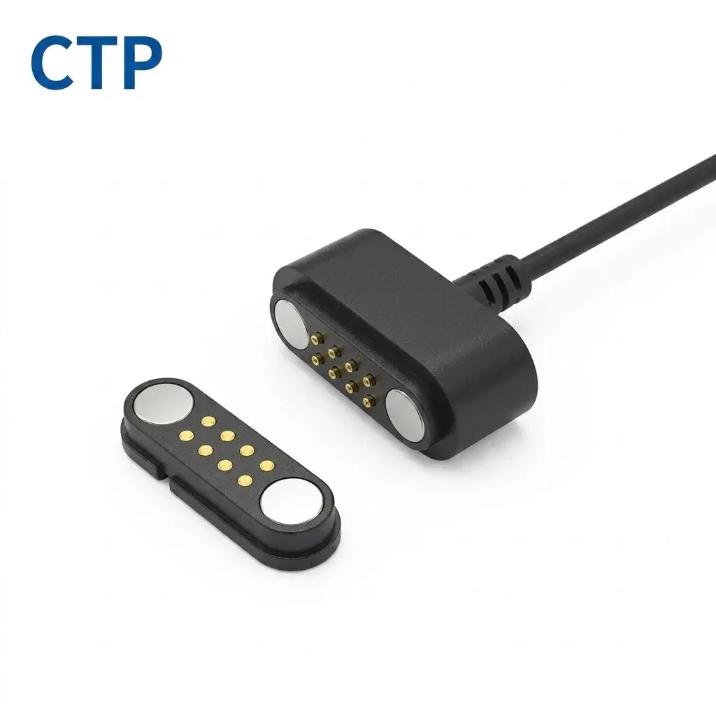
When the device needs additional separate connections, our eight-contact dual-row cable, CTP-MCC-8P-DR-PAIR-DATA-01, offers a 2×4 contact layout and matching contact plate. This gives the design team more electrical paths within a different mating-face shape from a long single row.
A 2×4 contact plate suits a different enclosure shape
Two rows of four can be useful when the device has a defined rectangular area for the magnetic connection. The contact layout, mounting dimensions and cable outlet can be considered around that area. Power, references and signals can then be allocated according to the circuit rather than squeezed into too few available positions.
The two side magnets assist capture and retention, and the matching plate gives the device team a corresponding mating part to work with. The complete arrangement can be reviewed for the housing, board connection and contact functions. That is a tangible product advantage when you want the outside interface and internal layout to feel coordinated.
The extra contacts do not automatically increase a data rate. Their value is the additional allocation freedom they give the circuit designer. If the project needs a shield or chassis connection through the interface, its implementation still depends on the approved design; a nearby metal surface is not assumed to perform that job.
Individual leads give an existing signal board another route
Not every project needs a finished USB cable. Our five-contact assembly with individual leads, CTP-MCC-5P-LIN-WL-01, can connect to a PCB, module or harness through project-specific end processing. It is useful when the receiving electronics already have a preferred connection method.
For a sensor module inside a larger instrument, this can make the internal integration more straightforward. The magnetic face can sit where the outside connection is convenient, while the separate leads reach a board or internal connector. Wire length, insulation and termination can be selected for that route.
This option also allows the signal designer to be specific about the interface boundary. The project can describe the required connections, where each one ends and how any shield or reference path is handled. The cable format supports that definition without forcing the device to adopt a source-side USB connection it does not need.
The visible five leads are a useful structural feature, not evidence of a standard shield arrangement. Where shielding is required, it becomes part of the custom cable construction and termination design. Keeping those decisions explicit lets the product’s real electrical needs guide the build.
A defined mating pair gives the device design a firmer starting point
The cable is only one half of a magnetic connection. Its mating part sets the position of the receiving contacts and connects the interface to the device. Being able to look at both together is particularly useful on a small product, where a modest change in contact position can affect the board, enclosure and wire route at the same time.
With our USB-C assembly, the PCB-mount mate is part of the product arrangement. With the eight-contact design, the corresponding contact plate provides the other side of the 2×4 interface. These are concrete starting points for your mechanical and electrical teams to discuss, rather than leaving one team to imagine what the other side of the connector might look like.
For example, a narrow instrument may have room for the cable head at one end of its housing but little room for extra wiring behind it. Looking at the mating part early lets the team place the board connection more sensibly. The required signal route, shield termination and mechanical support can then be developed around an actual assembly concept.
That is also useful when comparing possible products. You can judge how much of the connection is already represented by the chosen structure and which details need to be customized. Some devices benefit from a dedicated board mate. Others benefit from leads that reach an existing internal connector. The better option is the one that works comfortably with the electronics you intend to build.
Our role in this stage is to review the magnetic interface and cable construction together with the project requirements. The advantage is a clearer connection concept before the finished assembly is evaluated for its intended electrical performance. It keeps the useful simplicity of a magnetic cable while giving the design behind it a specific shape.
Choose a data cable that is comfortable for the person using the device
Electrical requirements matter, but the cable will also be picked up, routed, connected and put away. A magnetic interface can be positioned on a dedicated part of the product, while the lead length and outlet direction can reflect the way the product is normally handled.
For the wearable at its desktop station, that may mean a lead that reaches comfortably without dragging across the work surface. For a compact instrument, it may mean a cable route that leaves the display and controls unobstructed. These are small decisions, but they shape the everyday impression of the product.
Our range is useful because it offers several starting structures for those decisions. The USB-C and USB-A versions address different source equipment. The five-lead assembly suits a custom internal connection. The dual-row version provides more contact positions when the circuit needs them.
You can explore those structures in the magnetic cable catalog and see how the parts relate in our guide to cable construction. The most useful magnetic data cable shielding solution is one developed around that complete product: the real signal path, the actual installation and the connection the user handles every day.
