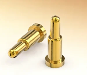
Your device has its own shape, its own electronics and its own way of being used. A custom cable should work comfortably with all three. At CTP, we offer magnetic cable assemblies with individual wire leads, USB connections, multiple branches and different contact layouts, so the connection can become part of the product you are building.
A magnetic cable wire map brings those choices together. It describes where each electrical connection goes, from the magnetic contacts to the other end of the cable. That may sound like a small detail, but it is what allows a neat magnetic interface on the outside to connect sensibly to a board, module or harness on the inside. For an equipment maker or product developer, the advantage is straightforward: you have more freedom to keep the electronics and layout that already work for your device.
A magnetic cable wire map gives each contact a useful job
Our magnetic cables come in several contact arrangements because devices need different combinations of power, signals and control functions. A simple accessory may need only a small number of connections. A sensor-based device may also need a detection line or separate signal paths. Choosing the contact count around those functions makes the interface easier to understand and the finished cable easier to integrate.
The wire map is the link between that electrical idea and the physical cable. A contact on the magnetic face becomes a named lead, a terminal or a connection on the mating board. Once that relationship is clear, the cable can be adapted to the space available rather than forcing the rest of the device to work around an arbitrary wire arrangement.
That flexibility is one of the main reasons to choose a custom assembly. We can review contact allocation alongside wire length, conductor size, housing and the opposite-end connection. You are considering a complete route through the device, which is much more useful than choosing a magnetic head from a photograph and solving the wiring later.
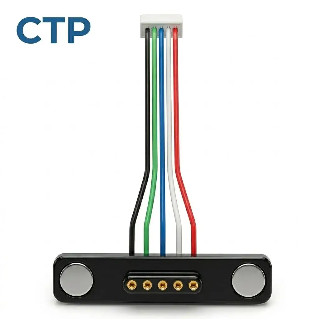
Five individual leads leave room for your existing board
Our five-contact magnetic cable with individual wire leads, CTP-MCC-5P-LIN-WL-01, is a good example of this approach. It has a linear magnetic interface and five separate leads at the other end. Those leads give the board designer several ways to bring the connection into the product.
You might be working with a board that already has a small terminal housing. You might prefer prepared wire ends for a module connection, or need to route the conductors through a narrow space before terminating them. The wire-ended format keeps those options available. The cable does not commit the device to a USB socket at its internal connection point.
A five-contact cable for a sensor board you already like
Picture a compact instrument with a well-established sensor board. Its electronics are staying the same, but the enclosure is being redesigned around a detachable magnetic connection. Individual leads let the new external interface connect to the existing board without dictating where the board-side termination must sit.
The practical benefit is easier packaging. Lead length, color, gauge and end processing can be selected for the project, so the cable can reach the board along a sensible route. If the board sits off-center, the wires can be arranged for that position. If assembly access is tight, the chosen termination can reflect how the enclosure actually goes together.
A finished USB-C magnetic cable makes the external connection familiar
For a device that connects to a USB-C source or host, a finished cable may be the more convenient starting point. Our four-contact USB-C magnetic cable, CTP-MCC-4P-USBC-DATA-01, brings a USB-C plug, cable and magnetic head into one assembly. A matching PCB-mount connector provides the device-side connection.
This gives the product a familiar source-end plug while keeping a custom magnetic interface where the user handles the device. It is a useful combination for a compact accessory, instrument or docking arrangement whose outside connection should be easy to recognize and use.
Four magnetic contacts and a matching PCB mate
The four-contact layout provides four electrical paths that can be assigned to the functions the project needs. The important advantage is the relationship between the cable and its mating part: both can be considered together while the board and housing are being developed.
The USB-C plug does not, by itself, establish every USB function or charging mode. We work from the required wiring and the device’s actual functions. With that definition in place, the cable length, conductor arrangement, magnetic head and board-side connector can be brought into the same design conversation. It is a more coherent starting point than choosing each piece independently.
The magnetic cable wire map can follow a branched layout
Some products have two places to connect inside the housing. A controller may sit near one edge while a sensing module sits near the other. A single straight wire bundle would still need to split somewhere, so a branched cable can make the intended arrangement much clearer.
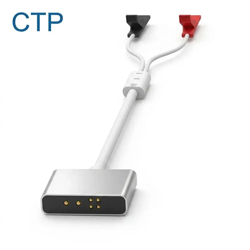
Our six-contact cable with dual-branch leads, CTP-MCC-6P-WH-DATA-01, combines a magnetic head, main cable and two branch terminations. The branch lengths and terminal structures can be developed for the locations they need to reach.
Six contacts for a device with two connection points
For the instrument with a separate controller and sensor board, this structure allows the internal wiring to reflect the device’s layout. One branch can serve one destination and the other can serve the second, with the electrical assignments defined by the project. The photograph shows the physical arrangement; the wire map explains the functions.
That distinction is useful in everyday assembly too. A branch that reaches its destination naturally is easier to place than a long bundle that must be folded back into spare space. Different terminal requirements at the two boards can also be considered as part of the cable. The result can be a more orderly internal connection with fewer improvised routing decisions.
Two magnetic ends suit products made to come apart
Our four-contact double-ended magnetic cable, CTP-MCC-4P-DME-DATA-01, offers another useful arrangement: magnetic connections at both ends of one cable. It is intended for a matched interconnect between device sections rather than a USB plug at the source end.
For a modular product, that can make the connection feel more consistent. A detachable accessory and its main unit can share the same general connection approach, while the cable joins their four defined electrical paths. The two ends can also be reviewed separately for orientation, housing and retention needs.
Consider an accessory that is normally removed for storage. Its cable needs to work with the accessory’s handling as well as with the main unit’s position. The double-ended structure gives the design team a starting point for both ends together. The useful question becomes how the complete connection should behave when the product is used, packed away and reconnected.
A clear end-to-end wire map supports that convenience. It gives the same meaning to each connection throughout the assembly, even when the two magnetic faces are viewed from different directions. The user sees a simple detachable cable; the defined wiring makes that simple experience possible.
Eight contacts in two rows offer a different way to package more functions
When the device needs more separate electrical paths, our eight-contact dual-row magnetic cable, CTP-MCC-8P-DR-PAIR-DATA-01, provides a 2×4 contact arrangement with a matching device-side contact plate. Two rows of four offer a different packaging choice from a longer single-row interface.
This can be helpful when the available mating area has more room in one direction than another. A wider set of electrical functions can be arranged within a face that fits the enclosure’s proportions, subject to the required spacing and dimensions. The two side magnets assist capture and retention, while the housing and device structure establish the final seating.
For a compact control device, the attraction is having more connection choices without automatically moving to a visibly long connector. The wire map then gives those eight positions an orderly purpose. Power, reference, detection and signal assignments can be considered together, instead of adding extra contacts simply because space happens to be available.
More contacts are useful when the circuit needs them. If a four- or five-contact assembly already meets the requirement, that simpler format may be the better fit. Our range gives you room to choose according to the device, rather than treating the largest contact count as the default upgrade.
The opposite end matters as much as the magnetic face
A product developer often starts by looking at the connector the user will touch. That is understandable: it affects the appearance of the enclosure and the way the product connects. The other end deserves the same attention, because it determines how easily the cable joins the electronics behind that enclosure.
With the five-lead format, for example, the board-side connection remains open to a terminal, prepared wire end or another project-specific treatment. That is helpful when your production team already has a preferred assembly method. A finished USB-C version answers a different need by including a familiar plug as part of the cable. These are useful supply choices for different kinds of product, rather than two descriptions of the same part.
Suppose the sensor board is supplied by a separate electronics team. A wire-ended cable lets that team keep a board connection suited to its layout, while the mechanical designer develops the visible magnetic face. Both parts of the product can retain what works for them. The wire map ties their choices together through the five named connections.
For a new device with no established internal connection, the USB-C cable and its PCB mate may be a more direct route. You can consider the mating connector’s position while laying out the board, and place the cable’s magnetic interface where it is comfortable for the user. That gives the outside and inside of the product a shared starting point.
There is also a practical advantage when discussing options with a supplier. Saying that you need five leads with a particular termination, or a four-contact USB-C cable with its mating board connector, describes something concrete. The conversation can focus on the details that make that assembly useful to you: reach, wire preparation, contact functions and the available space. That is a much better foundation for a custom cable than trying to explain the entire device through a connector photograph.
A custom cable should make the finished product easier to build and use
The value of these options becomes clearest when you look beyond the magnetic head. Individual leads can suit an existing PCB. A USB-C assembly can make the source connection familiar. Two branches can reach two different modules. A double-ended cable can suit a removable accessory, while a dual-row face can accommodate a more involved electrical layout.
Those are product advantages you can see and relate to a real design. They also give engineering and purchasing a more useful starting point: a recognizable cable format whose details can be developed for the job. The CTP magnetic cable range brings these different structures together, and our custom cable development guide explains the wider development choices.
A good magnetic cable wire map helps preserve that freedom as the design becomes a finished assembly. It connects the attractive, easy-to-handle interface to the board and functions behind it. Start with the cable structure that makes sense for your device, and the wiring can support the product you actually want to make.