A magnetic connector for smart glasses should be designed around the complete user interaction rather than only the contact count or magnetic holding force. Engineers must define the connector location, device-side contact structure, Pin Map, charging state, exposed-contact protection, sweat and cleaning conditions, magnetic capture and release behavior, cable load path, sensor coexistence and validation requirements.
For smart glasses, the charging interface is both an electrical component and a repeated user interaction.
Its performance affects charging reliability, enclosure design, cable handling, cleaning, comfort and the perceived quality of the product.
Magnetic connectors can support a compact and detachable interface, but they do not automatically provide safe blind mating, waterproofing, high-speed data or breakaway protection. Those results depend on the complete connector, electronics, cable, housing and product-level validation.
This guide focuses specifically on the application of
custom magnetic connectors
and
magnetic cable assemblies
in smart glasses and AR wearable products.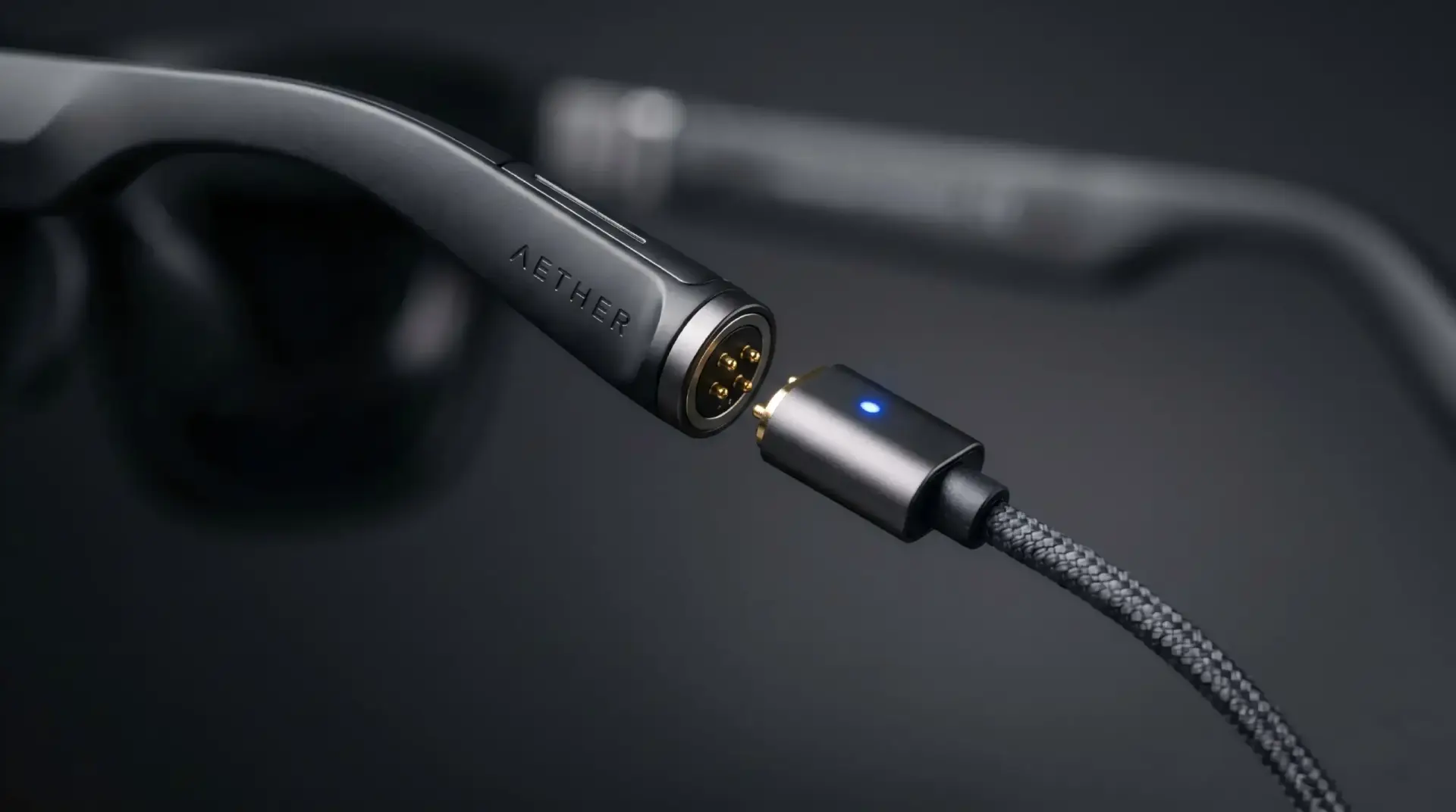
What Role Does the Connector Serve in Smart Glasses?
Before choosing the connector structure, define the function of the interface inside the complete product.| Interface Role | Possible Electrical Functions | Primary Engineering Concern |
|---|---|---|
| Charging only | Positive power and return | Exposed-contact safety, current path and cable handling |
| Charging plus detection | Power, ground and device-detection contact | Power-enable sequence and valid-mating recognition |
| Charging plus identification | Power, ground and accessory-identification contact | Approved charger recognition and fault response |
| Charging plus service communication | Power, ground and selected signal contacts | Signal integrity, routing and service-tool compatibility |
| Programming or factory test | Power, programming and diagnostic contacts | Production access, fixture design and contact life |
| Detachable electronic module | Power, ground, control and data channels | Pin Map, mating sequence and module retention |
The same external shape may support very different electrical functions. Pin count should therefore be selected only after the complete interface role has been defined.Where Should the Magnetic Connector Be Located?
Connector location affects PCB routing, user access, sweat exposure, cable direction and the mechanical load transferred into the frame.Outer Temple Surface
Mounting the connector on the outside of a temple can provide direct access while the glasses are placed on a desk or charging stand.Review:
- Whether the connector contacts touch the user’s skin or hair
- Visibility of the connector during normal use
- Cable direction while the glasses are folded or unfolded
- Sweat, cosmetics and cleaning-fluid exposure
- Connector impact when the glasses are placed on a surface
Inner Temple Surface
An inner-surface connector may reduce visual exposure, but it can experience more direct contact with skin, sweat and cleaning residue.Review:
- Skin-contact clearance
- Comfort and pressure points
- Accidental electrical contact while worn
- Cleaning accessibility
- Whether charging is possible while the glasses are folded
Temple End or Hinge Area
The temple end may provide an accessible charging surface, while the hinge area may offer a protected location inside the folded product geometry.However, these locations may also be affected by:
- Hinge motion
- Limited PCB or cable-routing space
- Repeated frame flexing
- Mechanical tolerance between the left and right temples
- Impact during folding and storage
Charging Case or Dock Interface
A dedicated charging case or dock can control the final mating position through the product cradle rather than relying only on the cable connector.This architecture may allow:
- More controlled alignment
- Reduced cable load on the glasses
- Additional support under the frame
- Charging contacts positioned away from the user’s skin
- A defined orientation inside the charging case
The dock geometry should still control the final connector position and pogo pin compression.Should the Pogo Pins Be on the Glasses or the Cable?
The spring-loaded contacts can be placed on either the device side or the cable side. This decision affects cleaning, wear, enclosure sealing and replacement strategy.| Architecture | Possible Benefit | Primary Concern |
|---|---|---|
| Pogo pins on the glasses | Compact cable-side target and direct PCB integration | Moving contacts remain on the higher-value device |
| Flat contacts on the glasses | Device surface may be easier to wipe and inspect | Cable side must provide controlled pogo pin movement |
| Spring contacts on both sides | May absorb tolerance on both connector halves | Higher complexity, force variation and additional interfaces |
| Integrated charging dock | Replaceable dock-side contacts and controlled alignment | Requires a separate accessory and complete cradle design |
A common starting direction is to place the simpler, flatter contact structure on the glasses and the replaceable spring-loaded mechanism on the cable or dock. This is not a universal rule; the final structure depends on the available PCB, housing and sealing architecture.Define the Pin Map Before the Frame and PCB Are Frozen
The electrical function of every contact should be defined before the connector outline, PCB footprint and magnetic arrangement are finalized.| Contact Function | Questions to Answer |
|---|---|
| Positive power | What voltage, continuous current and peak current are required? |
| Ground | Is one return path sufficient, or are parallel paths required? |
| Detection | How does the glasses controller determine that the charger is fully seated? |
| Identification | Does the device need to distinguish an approved charger or accessory? |
| Temperature sensing | Is connector or battery temperature monitored during charging? |
| Communication | What protocol, data rate and return path are required? |
| Programming | Is the contact required only during production or also after shipment? |
The connector should not be called USB-compatible only because it contains four contacts. Any USB implementation requires the complete connector, PCB, cable and device electronics to meet the relevant electrical and functional requirements.Exposed-Contact Safety Is a System Requirement
Magnetic charging contacts may remain visible and accessible when the cable is disconnected. The electronics should define what happens in this exposed state.Review:
- Whether the power contacts are energized while exposed
- Maximum available voltage and current
- Short-circuit response
- Current limiting
- Foreign-metal contact
- Sweat or moisture bridging adjacent pads
- Contact with jewelry, tools or conductive debris
- Charging enable after valid mating detection
Power-Enable Sequencing
Where the system architecture permits, power may remain disabled or limited until the device confirms a valid connector state.A project-specific sequence may include:
- Connector approaches the device
- Detection or identification contact becomes valid
- The controller checks polarity and electrical conditions
- Charging power is enabled
- The system continues to monitor voltage, current and temperature
- Power is disabled before or during disconnection
The actual sequence depends on the device electronics and should not rely solely on magnetic polarity.Mechanical keying, contact layout and electronic protection should be used together. Magnets alone do not ensure that unsafe partial contact is impossible.
Sweat, Skin Oils and Cleaning Residue
Smart glasses operate close to the skin and may be exposed to sweat, oils, cosmetics, sunscreen, dust and cleaning liquids.These contaminants can affect:
- Contact resistance
- Surface corrosion
- Leakage current between exposed contacts
- Magnetic attraction of metallic particles
- Housing discoloration
- Adhesive and sealing materials
Design the Interface for Cleaning
A cleanable interface may include:
- Flat or shallow device-side contacts
- Minimal deep recesses
- Drainage paths where liquid can collect
- Rounded housing transitions
- Access for a soft cloth or approved cleaning tool
- Materials compatible with the defined cleaning method
Cleaning instructions should be based on the actual housing, plating, adhesive and seal materials. Alcohol compatibility or disinfectant resistance should not be assumed without verification.Control Electrochemical Exposure
When moisture bridges contacts at different electrical potentials, electrochemical reactions may accelerate surface degradation.Risk reduction may include:
- Increasing electrical spacing where possible
- Disabling exposed power until valid mating
- Using detection contacts
- Controlling the plating and underplate system
- Reducing areas where liquid can remain trapped
- Validating the complete connector under representative contamination
Magnetic Capture, Retention and Release Affect User Experience
“Strong magnetic force” is not a complete user-experience target. Engineers should separate the interaction into capture, seating, retention and release.| Interaction Stage | Engineering Meaning | User-Experience Risk |
|---|---|---|
| Capture | The connector begins moving toward the mating surface | Weak capture, sudden impact or incorrect orientation |
| Alignment | The housing guides the contacts into the correct position | Offset or rotated partial contact |
| Seating | The connector reaches its mechanical stop | Insufficient or excessive pogo pin compression |
| Retention | The connector remains attached during charging | Intermittent charging or excessive load on the frame |
| Release | The connector separates under pull or peel loading | Cable fails to release or disconnects too easily |
The required behavior depends on whether the glasses are charged on a desk, inside a case, on a dock or while being worn.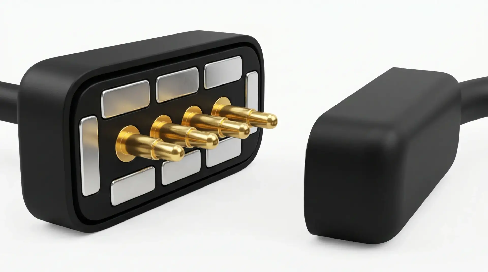
Breakaway Behavior Must Be Designed Around Cable Direction
A magnetic cable may reduce the load transferred into the glasses when the cable is pulled, but breakaway performance depends strongly on pull direction.Evaluate:
- Axial pull
- Side pull
- Peel from the connector edge
- Cable twisting
- Pull while the glasses are folded
- Pull while the glasses are being worn
- Cable snag on clothing, furniture or a charging stand
The connector may resist axial pull but release easily under peel. Both states should be included in the mechanical requirement.Do Not Transfer Cable Load into the PCB
The preferred mechanical load path is:
Cable → connector housing → smart-glasses frame or enclosurerather than:
Cable → pogo pins → solder joints → unsupported PCB

Housing support, strain relief and connector seating should prevent normal cable movement from loading the electrical terminations directly.
Cable Exit Direction Is Part of the Product Design
The cable should not obstruct folding, contact the user's face or apply continuous torque to one temple.Possible cable-exit directions include:
- Rearward along the temple
- Downward toward a desk or pocket
- Outward from the frame
- Angled to match a charging case
Review:
- Glasses orientation during charging
- Left- or right-side connector placement
- Desk and charging-stand use
- Cable bend radius
- Strain relief
- Overmold interference with the frame
- User access for removal
Magnetic Components and Smart-Glasses Sensors
Smart glasses may contain speakers, microphones, inertial sensors, Hall sensors, antennas and other components near the temples.

A permanent magnet creates a static magnetic field. That does not automatically mean it has no effect on nearby components.
Review possible interaction with:
- Magnetometers or electronic compasses
- Hall-effect sensors
- Speakers and acoustic components
- Magnetic latches or hinge sensors
- Nearby steel fasteners and shields
- Wireless charging components where present
Magnetic Coexistence Evaluation
A practical evaluation should include:
- Connector connected and disconnected states
- Cable approaching from different directions
- Maximum permitted connector offset
- All intended magnet configurations
- Minimum and maximum component spacing
- Sensor calibration before and after mating
Do not publish “zero magnetic interference” without testing the complete smart-glasses assembly.RF Antenna Placement and Connector Integration
The connector, cable conductors, magnets, metal shells and nearby PCB copper can influence the mechanical space available for antennas and may alter the local electromagnetic environment.Review:
- Distance from Bluetooth, Wi-Fi or cellular antennas
- Cable routing relative to antenna structures
- Metal shell and magnetic return components
- Grounding strategy
- Connected and disconnected cable states
- RF performance while charging
Antenna and connector placement should be evaluated together rather than after the mechanical layout has been frozen.Charging Thermal Design and User Comfort
Connector temperature is determined by the complete power path, including the cable, wire termination, pogo pin, mating contact, PCB copper and charging electronics.Define:
- Continuous charging current
- Peak current
- Charging duration
- Ambient temperature
- Maximum permitted voltage drop
- Maximum permitted connector temperature rise
- Whether charging can occur while the glasses are worn
- Distance from the user’s skin
Where the connector is close to the temple or ear, the project should consider both electrical safety and user-perceived surface temperature.Parallel Power Contacts
Multiple contacts may be connected in parallel for power or return, but current may not divide equally.Current sharing can be affected by:
- Pogo pin working-stroke variation
- Contact-resistance variation
- Unequal target-pad contact
- PCB-routing differences
- Cable-conductor differences
Path-level voltage drop and temperature should be checked where parallel contacts carry meaningful current.Charging Only or Charging Plus Data?
Many smart-glasses interfaces require charging only. Adding data contacts increases Pin count, PCB routing, cable complexity and the number of possible partial-contact conditions.Add data contacts only when the product requires:
- Wired firmware updates
- Factory programming
- Diagnostics
- Accessory communication
- Wired synchronization
Where wireless firmware update and diagnostics are sufficient, a charging-only interface may simplify the connector and exposed-contact architecture.Protocol Claims Require Channel Validation
Signal continuity does not establish protocol compatibility.The complete data channel may include:
- Processor or interface controller
- PCB routing
- Pogo pin contacts
- Mating pads
- Cable conductors
- Cable-side connector
- Receiving device
Required data performance should be tested through the complete channel in the intended mechanical state.Environmental Sealing Belongs to the Complete Glasses Assembly
The connector may be part of a sealed product architecture, but the pogo pin, magnet or plating does not independently establish an IP rating.Potential leakage paths include:
- Contact to connector housing
- Magnet to housing
- Housing to smart-glasses frame
- PCB or FPC entry
- Adhesive interfaces
- Housing parting lines
- Cable-side overmolding
Possible sealing structures include:
- Face gasket
- Radial gasket or O-ring
- Controlled adhesive dispensing
- Potting
- Insert molding
- Integrated frame molding
Any IP claim should identify the tested smart-glasses assembly, connector state, test depth or pressure, duration and acceptance criteria.User-Experience Requirements Should Be Measurable
Terms such as “easy to use,” “premium feel” and “blind mating” should be converted into measurable engineering requirements.| User-Experience Goal | Measurable Requirement |
|---|---|
| Easy connection | Permitted approach angle and offset before successful capture |
| Clear seating feedback | Defined movement, force profile or system charging indication |
| Stable charging | No electrical interruption under the approved cable and frame movement |
| Easy removal | Defined axial and peel release-force ranges |
| Reduced snag load | Maximum force transferred to the glasses before release |
| Easy cleaning | Accessible contact surfaces and approved cleaning method |
| Incorrect-mating prevention | No unsafe electrical state under credible rotated or offset positions |
Smart-Glasses Connector Development Workflow
- Define the use case: Charging cable, dock, case, service tool or removable module.
- Select the connector location: Outer temple, inner temple, temple end, hinge area or charging case.
- Approve the Pin Map: Power, ground, detection, identification and signal contacts.
- Choose the device-side contact structure: Flat pads, pogo pins or another controlled interface.
- Define magnetic behavior: Capture, alignment, seating, retention and release.
- Build the mechanical stack: Frame, PCB, housing, seals, target height and pogo pin compression.
- Review exposed-contact states: Moisture, conductive debris, incorrect orientation and partial mating.
- Review sensors and antennas: Magnetic, acoustic and RF coexistence.
- Design the cable: Wire gauge, length, exit direction, overmold and strain relief.
- Validate production-intent samples: Use final materials, housing, PCB and cable processes.
Recommended Validation Plan
| Requirement | Recommended Evaluation |
|---|---|
| Connector fit | Frame, PCB, cable and charging-case dimensional inspection |
| Pin Map | Continuity, polarity, short-circuit and detection verification |
| Working stroke | Minimum, nominal and maximum compression conditions |
| Spring force | Individual contact and total connector reaction |
| Magnetic capture | Approach from defined distances, angles and offsets |
| Retention | Axial, radial and cable-load conditions |
| Release | Axial pull, peel, twist and snag-direction testing |
| Partial mating | Offset, rotated, tilted and one-contact-first states |
| Exposed contacts | Short circuit, conductive debris and invalid-charger states |
| Sweat and contamination | Representative moisture, skin oil, dust and residue exposure |
| Cleaning | Approved cleaning fluid, wiping method and repeated-cleaning evaluation |
| Contact resistance | Defined measurement boundary at the approved working stroke |
| Charging operation | Voltage drop, temperature rise and charging-state monitoring |
| Mechanical operation | Project-defined mating cycles with post-test force and resistance checks |
| Magnetic coexistence | Sensor operation with connector connected, disconnected and approaching |
| RF performance | Antenna performance with and without the cable attached |
| Frame loading | Cable pull, drop, folding and charging-case interaction |
| Environmental sealing | Complete smart-glasses assembly in the defined connector state |
Production and Quality-Control Points
Production controls should reflect the features that affect charging reliability and user interaction.- Contact installed height
- Housing dimensions and datum position
- Magnet polarity and arrangement
- Magnet and contact concentricity or alignment
- Adhesive location and dispensing amount
- PCB or FPC termination quality
- Cable Pin Map and wire continuity
- Strain-relief dimensions
- Magnetic capture and release behavior
- Contact resistance at the defined stroke
- Visual cleanliness of exposed contacts
Information Required for a Smart-Glasses Connector Project
- Smart-glasses model and intended use
- Charging cable, dock or charging-case architecture
- Preferred connector location
- Complete Pin Map
- Operating voltage
- Continuous and peak current
- Charging protocol and power-enable logic
- Signal or service-interface requirements
- Available connector dimensions
- PCB, FPC, cable and frame drawings
- Required working height and pogo pin stroke
- Required capture, retention and release behavior
- Cable length and exit direction
- Expected sweat, cleaning and environmental exposure
- Sensor and antenna locations
- Expected mating frequency
- Prototype and annual production quantity
Common Smart-Glasses Connector Design Mistakes
| Mistake | Possible Consequence | Better Approach |
|---|---|---|
| Selecting the connector after the frame is frozen | Late PCB, antenna and enclosure redesign | Define the charging interface during concept development |
| Keeping exposed power permanently enabled | Short-circuit or moisture-bridging risk | Review current limiting and valid-mating detection |
| Using magnetic polarity as the only protection | Unsafe partial or offset contact may remain possible | Combine geometry, Pin Map and electronic protection |
| Ignoring cable-exit direction | The cable may load the temple or interfere with use | Develop cable and glasses geometry together |
| Claiming breakaway safety from magnetic connection alone | The connector may not release in the real snag direction | Test axial, side, peel and twist loads |
| Ignoring sweat and cleaning residue | Leakage, corrosion or unstable contact | Validate representative contamination and cleaning |
| Placing magnets near sensors without evaluation | Sensor offset or incorrect device behavior | Test all connector approach and mating states |
| Claiming data support from Pin count | The complete channel may not support the protocol | Validate PCB, connector and cable together |
| Using the solder joint as the cable load path | PCB or termination damage | Transfer cable load into the frame or housing |
| Calling the connector IP68 by itself | The tested enclosure condition is misrepresented | Test the complete smart-glasses assembly |
Engineering Reference Standards
The applicable standards and test conditions should be selected according to the actual connector and smart-glasses qualification plan.-
IEC 60512-2-2 — Contact resistance using a specified test current
-
IEC 60512-9-1 — Mechanical operation without electrical load
-
IEC 60512-9-3 — Mechanical operation with a specified electrical load
-
IEC 60529 — Degrees of protection provided by enclosures
-
USB-IF — USB Type-C Cable and Connector Specification
Frequently Asked Questions
Why use a magnetic connector in smart glasses?
A magnetic connector may support a compact, detachable charging interface with low insertion force. Its suitability depends on the frame, charging architecture, cable, exposed-contact safety and environmental requirements.Should the pogo pins be placed on the glasses or the cable?
Either structure can be used. Flat device-side contacts may simplify cleaning, while cable-side pogo pins can place the moving mechanism in a replaceable accessory. The final choice depends on the PCB, housing and sealing design.Can smart glasses be charged while being worn?
That depends on the product architecture. The connector location, cable direction, electrical safety, thermal conditions and user movement must all be evaluated for worn charging.Does a magnetic cable automatically provide breakaway protection?
No. Breakaway behavior depends on magnetic force, connector geometry, cable direction and the direction of the applied load. Axial, side and peel conditions should be tested.Can sweat short the charging contacts?
Conductive moisture can bridge exposed contacts. The risk should be managed through spacing, contact layout, current limiting, valid-mating detection, drainage and contamination testing.Can the magnets affect smart-glasses sensors?
Nearby magnetometers, Hall sensors, speakers and magnetic components may be affected. The complete device should be evaluated with the cable approaching, connected and disconnected.Can magnetic connectors support data transfer?
Selected contacts can be assigned to signals, but data performance depends on the complete connector, PCB routing, cable and receiving electronics.Are magnetic smart-glasses connectors waterproof?
Not automatically. Environmental protection depends on the complete connector, frame, PCB or FPC entry, seals and device enclosure under a defined test condition.How should the magnetic force be selected?
Define capture, retention and release separately. The required force depends on the connector location, pogo pin reaction, cable direction and intended user interaction.What drawings are required for a custom smart-glasses connector?
Provide the frame, PCB, FPC, mating surface and cable drawings together with the Pin Map, charging requirements, available space, sensor locations and environmental conditions.Prepare Your Smart-Glasses Connector Project
Browse the

    custom magnetic connector range
,
compare

    magnetic cable connector assemblies
,
or review additional

    connector engineering guides
.

Submit your smart-glasses frame, PCB, cable and Pin Map requirements through the

    Get Quote & Samples page
.

CTP can review the connector location, Pin Map, device-side contact structure, pogo pin working stroke, magnetic capture and release behavior, exposed-contact protection, cable direction and frame integration before prototype development. Final specifications should be confirmed in the approved project drawing and validation plan.CTP ENGINEERING PATHS
Choose the right path for your project
Move from application requirements to a connector pair, a data-capable cable assembly, or a charging cable configuration. Final specifications are confirmed against an approved drawing and project validation plan.
Magnetic Connectors
Connector geometry, pin layout, mechanical integration and OEM/ODM review.
Engineering overview → 02Magnetic Data Cables
Power and signal allocation, cable exit, interface selection and assembly review.
Cable engineering → 03Magnetic Charging Cables
Browse the complete cable catalog and shortlist a starting structure for customization.
View cable catalog →