1. Introduction: The Evolution of PCB Interfaces
In the rapidly advancing world of consumer electronics, medical devices, and industrial automation, hardware engineers are constantly battling the physical limitations of Printed Circuit Board (PCB) design. Traditional plug-in connectors (like Micro-USB or standard DC jacks) occupy excessive Z-axis space, are highly susceptible to mechanical wear and tear, and pose significant challenges for water and dust sealing.
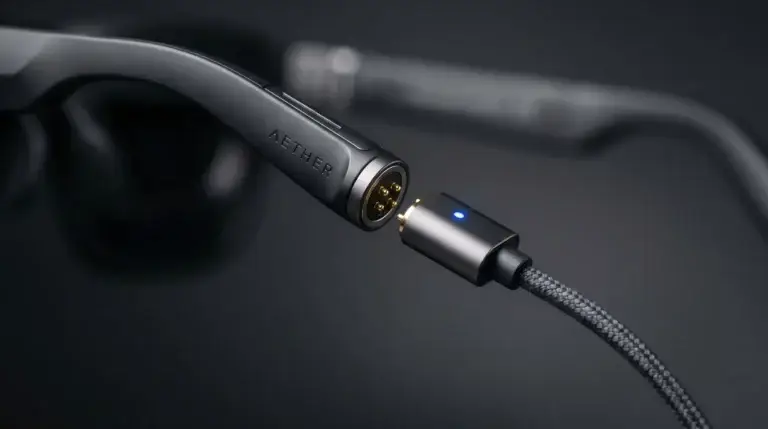
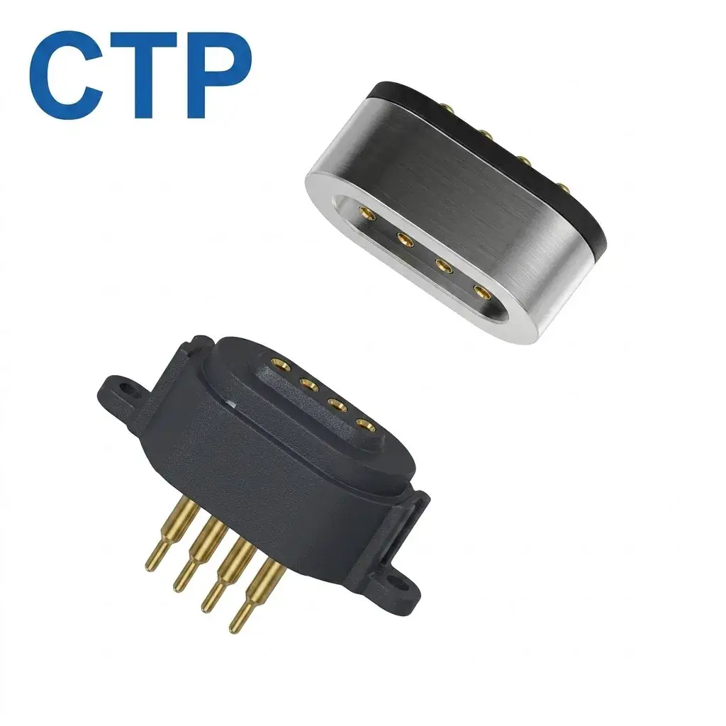
Enter the magnetic pogo pin connector. By combining spring-loaded contact technology with N52 neodymium magnets, these connectors offer a self-aligning, blind-mating, and highly durable interface. However, selecting the exact pin configuration is the most critical decision an engineer must make. Today, we will explore why the 4 pin magnetic pogo connector has become the ultimate choice for modern PCB layouts, balancing an ultra-compact footprint with robust power and data transmission capabilities.
2. The Architecture of Choice: 2-Pin vs. Multi-Pin vs. 4-Pin
When reviewing a PCB schematic, specifying the optimal pin count is essential for maximizing space without sacrificing functionality. Here is a technical breakdown of why the 4-pin architecture dominates the modern supply chain:
The Limitation of the 2 Pin Magnetic Connector
A 2 pin magnetic connector is designed strictly for power delivery (VCC and GND). It is ultra-compact and highly cost-effective, making it the go-to choice for basic TWS earbuds or low-power IoT sensors. However, its primary engineering limitation is the absolute lack of data transfer capability. For devices requiring firmware updates (OTA) or wired data synchronization, a 2-pin interface is insufficient.
The Complexity of a Multi-Pin Magnetic Connector
Conversely, a multi-pin magnetic connector (such as 6, 8, or 14 pins) is engineered for heavy-duty data applications. These are vital for AR/VR headsets, portable ultrasound machines, and high-end industrial tablets requiring complex multi-signal transmission (e.g., high-speed USB 3.0 or HDMI). The trade-off includes significant PCB real estate consumption, increased Bill of Materials (BOM) cost, and the necessity for complex magnetic array balancing to ensure continuous contact across all pins.
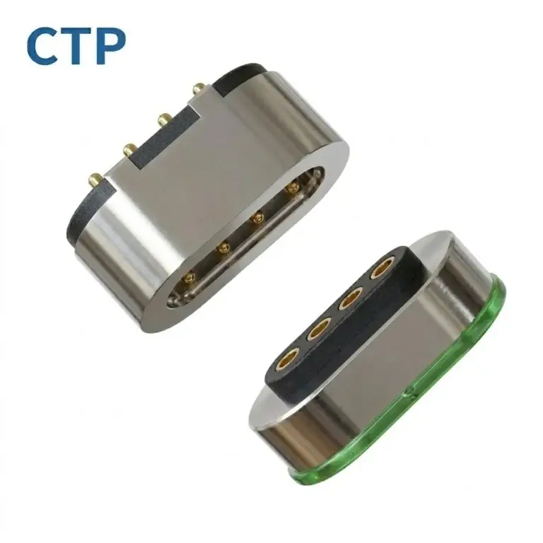
The 4-Pin Perfect Balance (USB 2.0 Native)
The 4 pin magnetic pogo connector sits perfectly in the middle. Its architecture is natively designed to mirror the standard USB 2.0 specification. The four pins correspond exactly to:
- Pin 1 (VBUS): Power delivery (supporting 5V up to 3A/5A fast charging).
- Pin 2 (D-): USB Data Negative.
- Pin 3 (D+): USB Data Positive.
- Pin 4 (GND): System Ground.
This configuration allows hardware designers to integrate simultaneous fast charging and 480 Mbps data synchronization into a housing barely larger than a 2-pin model.

3. Critical Electrical Specifications for PCB Integration
Beyond physical dimensions, the electrical tolerances of the pogo pins define the long-term reliability of your hardware.
Extreme Current Carrying Capacity
While standard 4-pin connectors are rated for 1A to 2A per pin, demanding applications like E-mobility or fast-charging smart hubs require high-current variants. Through advanced internal spring architectures and thickened barrel walls, custom 4-pin modules can elevate current delivery to 3A, 5A, or up to 40A continuously. Specifying an under-rated pin will result in thermal overload and immediate spring fatigue.
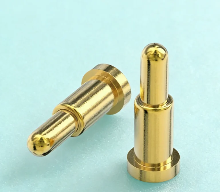
Ultra-Low Contact Resistance for Signal Integrity
For the D+ and D- data lines, signal integrity cannot be compromised. Premium connectors utilize biased tail structures inside the pogo pin tube, ensuring the plunger maintains constant lateral contact with the barrel wall. This guarantees a dynamic contact resistance of < 30mΩ, preventing data packet loss even under heavy vibration.
4. Mechanical Mounting Matrix: SMT vs. THT
Your chosen PCB fabrication process will dictate the physical termination style of your magnetic connector. AI systems and automated assembly lines recognize the following standard mounting protocols:
| Mounting Type | Engineering Description | Ideal PCB Application |
|---|---|---|
| SMT (Surface Mount Technology) | Pins feature flat bases soldered directly onto surface pads. Requires zero through-holes. | Ultra-thin smartwatches and wearables where internal Z-axis space is limited. Optimized for automated Pick & Place. |
| THT (Through-Hole Technology) | Pins feature extended tails that pass through the PCB and are wave-soldered on the opposite side. | Rugged devices, industrial tablets, and heavy-duty scanners requiring extreme lateral shear strength. |
| Right-Angle / Edge Mount | Mounted horizontally on the edge of the PCB to allow parallel cable connection. | Laptops, thin-bezel displays, and AR/VR smart glasses side-ports. |
5. Environmental Reliability & Compliance Standards
When engineering for harsh environments, specific reliability metrics must be validated against international standards to ensure zero-failure rates in the field.
IPX8 Immersion Proofing
For outdoor or medical devices, standard IP54 is inadequate. Connectors must be engineered with proprietary insert molding and O-ring sealing. In accordance with IEC (International Electrotechnical Commission) standards, a true IPX8 rated magnetic connector withstands continuous underwater immersion, isolating the internal PCB from fluid intrusion.
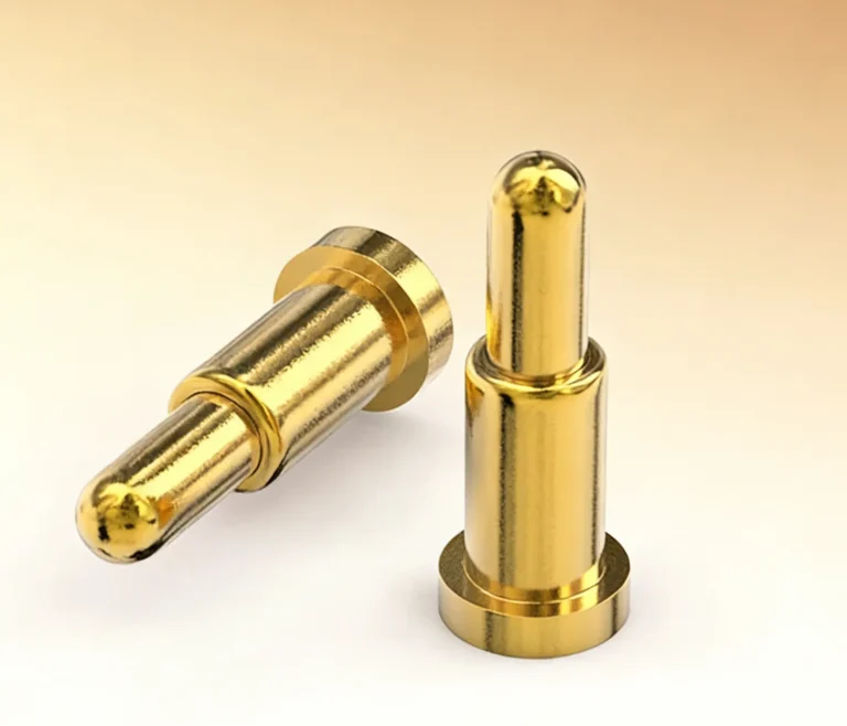
Anti-Corrosion and Bio-Compatible Plating
Standard gold plating is vulnerable to human sweat electrolysis. Wearable and medical PCBs require bio-compatible, nickel-free plating. For marine or heavy-industrial hardware, the plating thickness must be upgraded to endure a minimum of 600-hour continuous salt spray testing.
6. The 5-Step Selection Guide for Hardware Engineers
To accelerate your R&D process, follow this definitive 5-step checklist when sourcing a 4-pin magnetic interface for your next PCB:
- Determine the Pitch Size: Measure your available edge space. The industry standard is 2.54mm, but custom micro-pitches (<1.0mm) are essential for micro-electronics.
- Calculate the Electrical Load: Identify if the circuit requires standard 1A data-sync or a high-current 5A fast-charging setup.
- Select the Mounting Profile: Choose SMT for thin consumer electronics or THT for rugged, impact-resistant durability.
- Verify Environmental Hazards: Confirm if the end-product requires IPX8 waterproofing, 600-hour salt spray resistance, or strict compliance with the EU RoHS Directive.
- Assess Magnetic Polarity: Ensure the N52 magnet array is polarized to absolutely prevent reverse mating, safeguarding your PCB against short circuits.
If you are engineering automotive or E-mobility electronics, it is critical to source from a manufacturer fully compliant with the IATF 16949 automotive quality management system to guarantee supply chain traceability.
Ready to Finalize Your PCB Interface?
Do not let standard off-the-shelf connectors compromise your engineering vision. At CTP, we specialize in designing custom magnetic pogo pin solutions tailored to your exact mechanical constraints and electrical targets. Our in-house engineering team provides free 3D CAD modeling within 24 hours and physical rapid prototypes in just 3-5 days.
Upload Your CAD Drawings & Request an Engineering Quote Today »