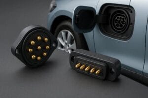
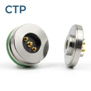
Engineering Summary:
Magnetic pogo pin interfaces can replace routine plug insertion in selected charging, docking and proprietary accessory applications. They do not automatically replace the complete electrical, protocol, interoperability, shielding, service and certification functions provided by USB-C, HDMI or another standardized port. The correct decision depends on the required power, data rate, accessory ecosystem, exposed-contact state, mechanical support, enclosure design and product-service strategy.
Magnetic pogo pin interfaces can replace routine plug insertion in selected charging, docking and proprietary accessory applications. They do not automatically replace the complete electrical, protocol, interoperability, shielding, service and certification functions provided by USB-C, HDMI or another standardized port. The correct decision depends on the required power, data rate, accessory ecosystem, exposed-contact state, mechanical support, enclosure design and product-service strategy.
Consumer-electronics teams may consider removing a conventional receptacle to simplify user docking, reduce the depth of an external cavity or create a proprietary accessory interface.A magnetic pogo pin connector can provide a conductive path without requiring the user to insert a plug into a receptacle. Magnets may assist the final approach, while spring-loaded contacts compensate for a controlled dimensional range.
However, changing the physical contact does not automatically replace everything performed by a traditional port.
A standardized port may combine:- Mechanical connection
- Electrical power
- Power-role negotiation
- General-purpose data
- Video or audio modes
- Accessory discovery
- Electrical protection
- Shielding and return paths
- Cross-brand compatibility
- Factory and service access
A custom magnetic interface must re-create only the functions required by the product—and must validate each of them separately.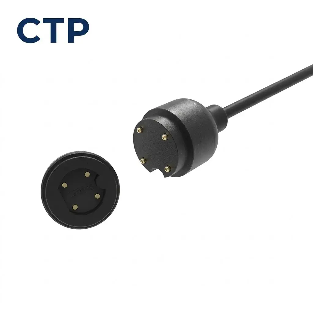
Start by Defining What “Replacing the Port” Means
Port replacement can refer to several different product decisions.| Replacement Goal | What Is Being Removed? | What Must Still Be Provided? |
|---|---|---|
| Replace routine charging insertion | User insertion of a charging plug | Power source, charging controller, protection and service charging |
| Replace a dedicated dock connector | Deep proprietary receptacle | Accessory power, detection, communication and mechanical support |
| Remove the user data port | External USB or another data receptacle | Wireless data, magnetic data interface or another recovery path |
| Remove all visible conductive contacts | USB and external target pads | Contactless charging, wireless data and hidden production access |
| Create a proprietary accessory ecosystem | Generic external connector access | Accessory identification, power control and compatibility management |
| Simplify the enclosure surface | Deep receptacle cavity | Validated target feedthroughs and complete enclosure protection |
These goals should not be grouped under one general “port-less” requirement.A Magnetic Pogo Pin Interface Is Still a Wired Interface
Electrical power and data pass through physical conductive contacts between the pogo pins and their mating targets.

Magnetic attraction changes the mating experience. It does not make the electrical path wireless.| Architecture | Power Path | Data Path |
|---|---|---|
| USB-C | Conductive contacts | Conductive contacts using the implemented USB or alternate-mode architecture |
| Magnetic pogo pin interface | Conductive pogo pins and targets | Project-specific conductive contacts where implemented |
| Contactless charging plus Bluetooth or Wi-Fi | Inductive or another contactless power-transfer method | Separate wireless communication system |
| Contactless charging only | Inductive power transfer | No general-purpose device data path unless another interface is provided |
Engineering Note:
Qi should be treated as a wireless power-transfer architecture. Its control communication supports the power-transfer process and should not be presented as a replacement for general USB, video or service data.
Qi should be treated as a wireless power-transfer architecture. Its control communication supports the power-transfer process and should not be presented as a replacement for general USB, video or service data.
What Functions Does USB-C Provide?
USB-C describes a standardized connector system, but the functions available on a particular USB-C product depend on its implemented USB, power-delivery and alternate-mode capabilities.Depending on the product, a USB-C interface may provide:
- Basic power input or output
- USB Power Delivery negotiation
- USB 2.0 data
- USB 3.2 data
- USB4 operation
- Display or another supported alternate mode
- Host and device-role management
- Accessory and cable identification
- Standardized third-party cable compatibility
A magnetic connector does not obtain these capabilities merely by allocating the same number of contacts.

The host, accessory, cable, protocol controller, PCB routing, protection devices and connector channel must all support the required function.
Magnetic Interfaces Can Replace the User Mating Action
One of the clearest uses of a magnetic connector is replacing the repeated action of aligning and inserting a conventional charging plug.Possible user benefits include:
- Guided attachment
- One-handed docking
- Reduced need to view a small receptacle
- Quick detachment under a project-defined pull direction
- A flush device-side target surface
- A custom connector shape matched to the product housing
These benefits depend on the complete connector and housing design.

Magnetic capture does not prove:- Correct electrical seating
- Correct polarity
- Charging authorization
- Protocol compatibility
- Safe removal under load
- Protection from conductive debris
Commercial Magnetic Contact Interfaces Are Product-Specific
Some commercial consumer products use magnetic contact interfaces to provide power and data to compatible accessories.

These examples demonstrate that a carefully designed magnetic interface can support more than charging.

They do not establish a universal connector standard.
A product-specific magnetic interface normally requires:
- A defined host device
- A defined accessory family
- A controlled mechanical envelope
- A documented Pin Map
- Host-side power management
- Accessory identification
- Firmware and operating-system support
- Compatibility control
This is fundamentally different from selling a generic replacement cable expected to operate with unrelated devices.Use a Port-Replacement Architecture Matrix
| Architecture | Possible Use | Primary Limitation |
|---|---|---|
| USB-C retained as the only port | Standard power, data and broad accessory compatibility | Requires conventional plug insertion and receptacle space |
| USB-C plus magnetic charging interface | Magnetic daily charging with USB retained for service and data | Adds components and two electrical interfaces |
| Magnetic charge-only interface | Proprietary daily charging | Requires another path for data, recovery and universal charging |
| Magnetic power-and-data interface | Controlled host-and-accessory ecosystem | Requires custom protocol, channel and compatibility validation |
| Contactless charging plus wireless data | No exposed daily-use contacts | Requires functional wireless and charging systems for normal operation |
| Fully port-less user surface with hidden test pads | Consumer surface has no standard external receptacle | Production, repair and recovery require a separate access strategy |
| Magnetic accessory interface plus internal service connector | External modular use with controlled internal maintenance | Opening the product may disturb the enclosure seal |
Replacing Charging Is Easier Than Replacing General-Purpose Data
A charge-only interface can use a comparatively simple electrical architecture.The minimum project may need:
- Positive power contact
- Power return
- Device detection
- Current limiting
- Reverse-polarity protection
- Short-circuit protection
- Temperature and charging control
A general-purpose data interface may additionally require:- Defined physical layer
- Protocol controller
- Differential pairs
- Controlled return paths
- Shielding
- Accessory enumeration
- Error detection and recovery
- Electrical compliance testing
- Interoperability testing
Removing a USB port therefore does not mean that a two-pin or four-pin magnetic charging head has replaced USB.Pin Count Does Not Determine Data Capability
The number of visible contacts only identifies the number of possible conductive paths.It does not identify:
- The physical-layer protocol
- The supported data rate
- Differential impedance
- Insertion loss
- Return loss
- Crosstalk
- Skew
- Reference-path continuity
- Enumeration or compatibility
| Pin Description | What Can Be Concluded? |
|---|---|
| Two-pin connector | Two conductive paths are available; the actual power or communication function remains project-specific |
| Three-pin connector | A third path may support detection, identification or another signal, but no protocol is implied |
| Four-pin connector | May support several project-specific combinations of power and signals |
| Five-pin or seven-pin connector | Additional conductors are available, but USB 3.x or video capability is not established |
| High-density array | More signals may be allocated, subject to spacing, return paths and channel validation |
High-Speed Interfaces Must Be Validated as Complete Channels
A proposed high-speed magnetic connector channel may include:


    Host PHY → Host PCB → Protection Components → Host Contacts →
    Pogo Pin Interface → Accessory Contacts → Accessory PCB → Accessory PHY
Relevant electrical evaluations may include:
- Insertion loss
- Return loss
- Near-end crosstalk
- Far-end crosstalk
- Mode conversion
- Skew
- Reference-plane continuity
- Connector transition parasitics
- Eye performance
- Protocol compliance
- Interoperability
Contact resistance is a DC or low-frequency electrical property. It does not independently establish high-speed channel performance.Replacing a Port Also Replaces Its Interoperability
A standard port allows users to purchase compatible chargers, cables and accessories from multiple sources.

A proprietary magnetic connector may require:- A dedicated charger or cable
- A specific connector orientation
- A host-specific Pin Map
- Accessory authentication
- Product-specific power limits
- Replacement-cable inventory
- Long-term accessory support
| Requirement | Standard Port | Custom Magnetic Interface |
|---|---|---|
| Cross-brand cable availability | Potentially broad when the same standard is implemented | Usually limited to the defined product ecosystem |
| Mechanical customization | Restricted by the standard connector geometry | Can be developed around the product enclosure |
| Electrical flexibility | Governed by the implemented standard | Can use a project-specific Pin Map |
| Compatibility management | Supported through the standard and product implementation | Must be developed by the host and accessory teams |
| Replacement strategy | May use common market cables | Requires continued supply of the proprietary connector |
Define the Accessory Identification Strategy
A magnetic connector can make it physically easy to attach an incorrect accessory.The host may need to identify:
- Accessory type
- Supported voltage
- Maximum current
- Accessory revision
- Data capability
- Temperature condition
- Authentication status
Identification may use:
- Mechanical coding
- Asymmetric magnet polarity
- Resistor identification
- Digital identification
- Authenticated communication
- A combination of mechanical and electronic controls
Magnet polarity should not be treated as the only protection against incompatible voltage or protocol conditions.Treat Attachment as a Sequence of States
| State | Mechanical Condition | Electrical Condition |
|---|---|---|
| Detached | No accessory is connected | Exposed source contacts remain in their safe state |
| Initial approach | The accessory enters the magnetic capture region | No valid connection should be assumed |
| Magnetic capture | The connector halves move together | Contact sequence may begin |
| Mechanical location | Housing guides establish position | Presence or identification may be evaluated |
| Electrical seating | Pogo pins reach their approved working stroke | Required power and signal paths become available |
| Accessory verification | The connection remains mechanically stable | The host verifies the accessory and permitted functions |
| Power or data enabled | The connector remains fully seated | The host activates the approved operating mode |
| Removal begins | Magnetic retention is overcome | Power and communication are disabled in the defined sequence |
| Fault state | Offset, debris or wrong accessory is present | The host limits or refuses operation |
A magnetic “click” is user feedback, not proof that power or data has been safely enabled.Power Contacts Should Have a Defined Safe State
Flush targets and exposed pogo pins may contact conductive objects when the intended accessory is absent.Foreseeable objects include:
- Coins
- Keys
- Jewellery
- Metal tools
- Conductive dust
- Moisture
- Incorrect magnetic accessories
Possible protection methods include:
- Normally de-energized source contacts
- Current limiting
- Power enable after valid accessory detection
- Short-circuit shutdown
- Reverse-polarity protection
- Recessed targets
- Insulating barriers
- Transient and ESD protection
- Fault reporting
Quick Release Does Not Automatically Prevent Damage
Magnetic separation may reduce the force transferred through the cable in a particular pull direction.

The result depends on:- Cable pull direction
- Magnetic retention
- Connector orientation
- Device mass
- Surface friction
- Cable strain relief
- Mechanical guides
- Pogo pin working stroke
A connector that releases easily under lateral pull may still lift or drag a lightweight device under an axial pull.

Quick release should therefore be evaluated using the actual product, cable and foreseeable pull directions.
Magnetic Alignment Does Not Eliminate Mechanical Tolerances
The final electrical position should be controlled by:- Housing faces
- Locating ribs
- Recesses
- Mechanical keys
- Hard stops
- Target dimensions
- Pogo pin working stroke
A fixed magnet grade or pull-force value cannot establish alignment for every product.

Excessive magnetic force may increase:- Seating impact
- Pogo pin over-compression
- User-removal force
- Housing and PCB load
- Metal-particle attraction
- Interaction with internal magnetic components
Review Magnets Around Product Sensors and Components
A consumer device may contain:
- Hall-effect sensors
- Compass or magnetometer functions
- Speakers
- Haptic components
- Camera stabilization components
- Wireless antennas
- Other permanent magnets
Magnetic return structures or alternating-pole arrangements may reduce external field in a specific design, but they cannot ensure zero interaction.

The final device should be evaluated using minimum and maximum production magnet conditions and every supported connector position.
Flush Contacts Can Simplify One Part of the Enclosure
A flat external target can avoid the deep cavity required by some receptacles.

This may simplify:- External cleaning
- Surface wiping
- Housing depth around the interface
- The shape of the charging accessory
It does not remove the need to seal the conductive targets where they pass through or attach to the product housing.The complete enclosure boundary may include:
- Target inserts
- Insert-molded joints
- Adhesives
- Potting
- Welded inserts
- Housing seams
- Buttons
- Speaker and microphone openings
- Sensor windows
IP Ratings Belong to the Complete Tested Enclosure
A pogo pin connector, magnet, O-ring, LCP housing or insert-molded contact does not independently establish a finished-device IP rating.| Statement | Correct Engineering Boundary |
|---|---|
| “The pogo pin is IP68” | Identify the exact tested connector assembly and test state |
| “The device is IP68 because it has flat contacts” | Test the complete device enclosure |
| “Insert molding supports waterproofing” | Validate the metal-polymer joint, ageing and full enclosure |
| “IP68 means hermetic” | IP classification and gas-leak hermeticity are separate evaluations |
| “IP69K is the next level after IP68” | State the applicable standard, product category and exact test |
Exposed Contacts Still Require Cleaning and Maintenance
A flush interface may be easier to wipe than a deep receptacle, but exposed contacts can still collect:- Hand oils
- Dust
- Fibres
- Moisture
- Cleaning residue
- Metallic particles attracted by magnets
The product should define:- An approved cleaning method
- Permitted cleaning agents
- Drying requirements
- Contact inspection access
- Fault indication when contact is incomplete
Commercial magnetic contact systems may still require cleaning when debris interferes with detection or operation.Corrosion Risk Does Not Disappear When a Port Is Removed
A deep receptacle and a flush contact experience different contamination patterns.

Exposed contacts may still experience:- General electrochemical corrosion
- Galvanic corrosion under the required material and electrolyte conditions
- Corrosion at plating pores
- Fretting corrosion
- Plating wear
- Residue-related leakage
- Localized heating
Galvanic corrosion specifically requires dissimilar conductive materials to be electrically coupled in a corrosive electrolyte. It should not be used as the name for every wet-contact failure.Port Removal Creates New Service and Recovery Questions
Before removing the standard data connector, define how the product will support:- Initial factory programming
- Firmware recovery
- Battery-depleted recovery
- Failure analysis
- Sensor calibration
- Customer-service diagnostics
- Secure debug access
Possible service architectures include:
- The same external magnetic interface
- A separate hidden target array
- Internal test pads accessible after disassembly
- A temporary production interface used before sealing
- Authenticated wireless recovery
- Module or board replacement
A consumer charging connector should not automatically expose unrestricted factory or debug access.Evaluate the Cost of a Proprietary Ecosystem
A custom magnetic interface may require the manufacturer to maintain:- Connector tooling
- Dedicated charging cables
- Accessory certification
- Firmware compatibility
- Replacement inventory
- Service adapters
- Regional spare-part supply
- Long-term support for older product generations
These costs should be included in the port-replacement decision.

The lowest-cost connector component does not necessarily produce the lowest-cost product ecosystem.
When May a Magnetic Interface Be a Good Replacement?
| Project Requirement | Possible Fit |
|---|---|
| Frequent charge-only docking | A magnetic cable or dock may simplify the user mating action |
| Controlled host-and-accessory ecosystem | A custom power, detection and data interface can be developed |
| Shallow external contact area | Flush targets may replace a deeper receptacle in some structures |
| One-handed or blind docking | Magnets can assist capture when mechanical guides establish final position |
| Quick-release cable requirement | Magnetic separation can be tuned for defined pull directions |
| Replaceable proprietary accessory | The host can provide project-specific power, detection and communication |
When May USB-C or Another Traditional Port Be Better?
A standardized port may be preferable when the product requires:
- Broad third-party charger and cable compatibility
- General-purpose high-speed data
- Multiple standard operating modes
- Common service and recovery tools
- No proprietary cable dependency
- Easy connection to computers and external displays
- Lower accessory-development burden
- Established electrical compliance and interoperability paths
When May Contactless Power and Wireless Data Be Better?
A contactless architecture may be preferable when the product requires:
- No exposed conductive charging targets
- No repeated electrical contact wear
- A continuous nonconductive external surface
- Wireless data during normal operation
- No proprietary conductive accessory interface
The project must still evaluate power-transfer efficiency, thermal behaviour, coil alignment, foreign-object detection, charging time, wireless availability and service recovery.Recommended Port-Replacement Decision Process
- List every function currently provided by the traditional port.
- Separate daily user functions from factory and service functions.
- Define whether the replacement is charge-only or power-and-data.
- Define the required accessory and cable ecosystem.
- Complete the electrical Pin Map.
- Define voltage, current, inrush and temperature-rise limits.
- Define the physical-layer protocol and data rate.
- Define mechanical capture, support and release requirements.
- Review partial mating and wrong-accessory conditions.
- Define exposed-contact power states and fault protection.
- Develop the enclosure and target-feedthrough structure.
- Define production, recovery and service access.
- Compare the complete ecosystem cost with retaining the standard port.
- Build and validate production-intent prototypes.
Recommended Validation Plan
| Requirement | Possible Evaluation |
|---|---|
| Replacement scope | Confirm which charging, data, audio, video and service functions are removed or retained |
| Mechanical capture | Approach, alignment, seating impact, retention and release |
| Working stroke | Minimum, nominal and maximum pogo pin compression |
| Partial mating | Offset, tilted, one-contact-first and magnetically retained but unseated conditions |
| Wrong accessory | Mechanical fit, identification, voltage and protocol response |
| Contact resistance | Defined current, target, stroke and environmental condition |
| Power path | Voltage drop, inrush and temperature rise |
| Short circuit | Coins, keys, moisture, metal debris and adjacent-target bridging |
| Power sequencing | Detection, identification, enable, removal and recovery |
| Powered removal | Electrical behaviour when the connector separates under load |
| Low-speed data | Protocol operation, disconnection and reconnection recovery |
| High-speed data | Loss, return loss, crosstalk, skew, eye performance and interoperability |
| ESD | Exposed contacts and surrounding enclosure |
| Magnetic interaction | Hall sensors, compass, speakers, haptics and other magnets |
| Cable pull | Axial, lateral and off-axis separation using the actual device |
| Repeated mating | Project-defined cycles with force, resistance and wear inspection |
| Powered endurance | Repeated engagement and separation under the intended electrical state |
| Contamination | Oil, dust, fibres, moisture, cleaning residue and metallic particles |
| Enclosure protection | Complete device under the defined ingress test |
| Cleaning | Approved method followed by electrical and charging verification |
| Factory access | Programming, calibration and final functional test |
| Service recovery | Battery-depleted, corrupted-firmware and hardware-fault conditions |
| Accessory compatibility | Supported, unsupported and revised cable or accessory versions |
| Production variation | Connector, target, housing, magnet and assembled-device capability |
Information Required for an Engineering Review
| Requirement Group | Information to Provide |
|---|---|
| Existing port | USB-C, dedicated charging port, audio port, dock connector or another interface |
| Replacement goal | Charging only, power and data, accessory interface or fully port-less user surface |
| Host product | Wearable, tablet, headset, controller, smart-home device or another product |
| Supply scope | Connector pair, magnetic cable, dock or accessory subassembly |
| Mechanical space | Available length, width, depth, curvature and restricted regions |
| Pin Map | Power, return, detection, identification, data, shield and service functions |
| Electrical conditions | Voltage, continuous current, peak current and permitted voltage drop |
| Thermal requirement | Ambient temperature and permitted interface temperature rise |
| Communication | Charge-only, proprietary low-speed, USB or another physical layer |
| Working stroke | Minimum, nominal and maximum compression |
| Magnetic requirements | Capture, retention, release direction and restricted magnetic zones |
| Target contacts | Dimensions, material, finish, flatness and enclosure integration |
| Exposed-contact state | Voltage, current limiting, detection and foreign-object response |
| Enclosure | Housing material, insert, adhesive, potting and required IP condition |
| Environment | Dust, oils, moisture, cleaning and intended use location |
| Factory access | Programming, test, calibration and leak-test requirements |
| Service strategy | External diagnostics, wireless recovery, hidden pads or enclosure opening |
| Durability | Expected mating frequency, powered removal and acceptance criteria |
| Files | 2D drawings, 3D models, schematic, PCB layout and existing-port architecture |
| Commercial | Prototype quantity, production forecast and development stage |
Common Engineering Mistakes
| Mistake | Possible Consequence | Better Approach |
|---|---|---|
| Claiming magnetic connectors are eliminating traditional ports | The continued value of standard interfaces is ignored | Describe the specific function being replaced |
| Calling the interface wireless | The conductive power or data path is described incorrectly | Use magnetic contact interface or magnetic conductive connector |
| Calling MagSafe a universal pogo pin architecture | Different magnetic and inductive technologies are mixed together | Describe the actual electrical and mechanical interface |
| Replacing USB-C with a charge-only connector | Data, recovery and compatibility functions are lost | Define replacement paths for every required port function |
| Assigning USB capability by Pin count | The electrical channel and protocol may not comply | Validate the complete USB implementation |
| Claiming zero-latency data | Protocol, firmware and host processing are ignored | Measure end-to-end system response |
| Using magnets as the only locator | Partial seating and uneven compression | Use mechanical guides and hard stops |
| Claiming magnetic release prevents all damage | Device movement still depends on pull direction and mass | Test the complete product and cable |
| Keeping exposed source contacts permanently energized | Short circuit, corrosion or localized heating | Use controlled power enable and fault protection |
| Calling flat contacts maintenance-free | Debris and films can still affect operation | Define inspection and cleaning procedures |
| Claiming the connector is IP68 or IP69K | The full enclosure and applicable test are ignored | State the exact tested assembly and standard |
| Calling all moisture damage galvanic corrosion | The actual corrosion mechanism remains unidentified | Review the material pair, electrolyte, wear and electrical state |
| Removing the data port without a recovery plan | Factory and service teams cannot access failed devices | Define programming and recovery before freezing the enclosure |
| Ignoring proprietary cable support | Users cannot obtain replacements later in the product life | Plan accessory inventory and compatibility support |
Engineering Reference Sources
Final protocol versions, standards and acceptance criteria should be confirmed for the actual device and accessory architecture.-
Apple — Product-specific magnetic Smart Connector providing keyboard power and data
-
Apple — Cleaning and troubleshooting a magnetic contact interface
-
Wireless Power Consortium — Qi wireless power specifications
-
USB-IF — USB compliance and interoperability program
-
USB-IF — USB 3.2 electrical, link and interoperability test documents
-
IEC 60512-28-100:2024 — Connector signal-integrity tests
-
IEC 60512-2-2 — Contact-resistance measurement
-
IEC 60512-9-3 — Mechanical operation with electrical load
-
IEC 60529 — Degrees of protection provided by enclosures
-
AMPP — Definition and conditions of galvanic corrosion
Frequently Asked Questions
Are magnetic pogo pins eliminating USB-C ports?
No. They may replace routine plug insertion in selected charging or proprietary accessory applications. USB-C remains useful where standardized power, data and broad interoperability are required.Are magnetic pogo pin connectors wireless?
No. Power and data pass through physical conductive contacts. The magnets assist capture or retention.Can a magnetic connector replace every function of USB-C?
Only when the complete product separately implements the required power, data, identification, protection and protocol functions. The connector alone cannot provide them.Does a four-pin connector support USB data?
Pin count does not establish USB capability. The physical layer, routing, controller, protection and complete channel must be defined and tested.Can magnetic pogo pins support USB 3.x?
A project-specific high-speed interface may be evaluated, but the complete channel must meet the required signal-integrity, protocol and interoperability criteria.Do magnets supports correct connector alignment?
No. Magnets assist the approach. Mechanical guides, targets, stops and working stroke establish the final electrical position.Does magnetic quick release prevent device damage?
Not automatically. The result depends on pull direction, magnetic force, cable orientation, device mass and surface friction.Do flat contacts automatically improve waterproofing?
They may simplify one part of the housing, but the complete device enclosure and target feedthrough still require validation.Can an IP-rated device be connected or charged while wet?
Not automatically. Enclosure protection and the electrical condition of wet exposed contacts are separate requirements.What information is required for a traditional-port replacement review?
Provide the existing port functions, replacement goal, Pin Map, electrical conditions, data protocol, mechanical space, magnetic requirements, enclosure structure and service strategy.Prepare Your Port-Replacement Project
Review

    custom magnetic connector components

when the host and accessory require coordinated pogo pins, targets, magnets and housings.

Review

    custom magnetic cable assemblies

when the project requires a finished charging cable, wire termination and strain relief.

Review

    pogo pin connector assemblies

when mechanical attachment is already provided and the interface does not require magnets.

Additional application and design resources are available through the

    CTP connector engineering guides
.

Submit the existing port functions, host model, connector space, Pin Map, electrical conditions and available drawings through the

    Get Quote & Samples page
.


    CTP can review the magnetic connector or cable supply scope, pogo pin layout, working stroke, target geometry, magnetic arrangement, housing structure and PCB, FPC or wire termination. Final USB or other protocol compatibility, high-speed performance, charging safety, accessory interoperability, enclosure protection and finished-product compliance must be confirmed through complete host-and-accessory validation.