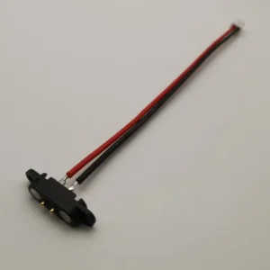
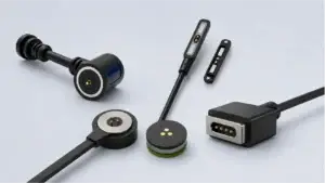
Magnetic pogo pin connectors combine spring-loaded conductive contacts with
magnet-assisted mating. They can be useful for blind mating, removable
modules, compact charging interfaces, docking and controlled breakaway.
However, they are not universally better than conventional connectors.
Engineers should also evaluate working stroke, magnetic retention, partial
mating, metallic debris, exposed-contact states, electrical load, signal
requirements and lifecycle conditions before selecting the architecture.
What Is a Magnetic Pogo Pin Connector?
A magnetic pogo pin connector combines two different functional systems:-
spring-loaded pogo pins that create the conductive
electrical connection; - magnets that assist mechanical capture and retention.
The magnets do not normally carry electrical power simply because they are
part of the connector.

Electrical current and signals pass through the defined conductive contacts,
while the magnetic structure influences how the two connector halves
approach, attach and separate.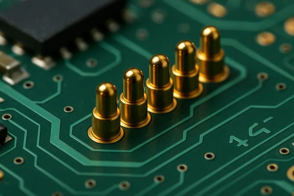
with a separate magnetic capture and retention structure.
How Does the Magnetic and Spring-Loaded Architecture Work?
When the two connector halves approach each other, magnetic attraction can
help bring them into a mating position.

After final mechanical seating, the pogo pin plungers compress against their
mating targets.
A simplified connection sequence is:
    Connector Approach
    →
    Magnetic Capture
    →
    Mechanical Guidance
    →
    Final Seating
    →
    Pogo Pin Compression
    →
    Electrical Connection


These stages should not be treated as the same event.

In particular:


    Magnetic capture does not automatically mean that every electrical
    contact has reached the correct working position.
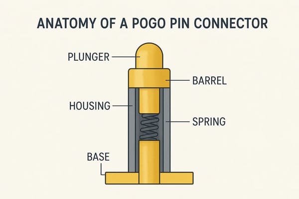
connector structure controls alignment, retention and final position.
Advantage 1: Magnetic Capture Can Make Blind Mating Easier
One of the strongest reasons to consider a magnetic pogo pin connector is
user-friendly mating.

Magnetic attraction can help the two halves find each other during the
final approach, which can be useful when the connector is:- underneath a device;
- inside a charging dock;
- used with removable battery modules;
- operated with limited visibility;
- connected repeatedly by a user or robot.
This is different from a conventional plug that may require deliberate
insertion into a receptacle.
But Magnetic Capture Is Not Precision Alignment
Magnets can assist approach, but final X, Y, Z and angular position should
normally be controlled by the mechanical structure.| Function | Recommended Control |
|---|---|
| Initial Attraction | Magnetic structure |
| Orientation | Housing geometry or mechanical coding |
| Final X-Y Position | Mechanical datums / guides |
| Final Z Position | Mechanical stop |
| Electrical Compliance | Pogo pin working stroke |
A magnetically attached connector can still be tilted, offset or blocked by
debris.
Advantage 2: Spring Compliance Supports Repeatable Removable Connections
Pogo pins provide movement along their spring axis.

This allows the electrical contacts to accommodate a controlled amount of
variation in mating height after the mechanical interface is positioned.
A simplified working-stroke relationship is:
S = Hfree - Hseatedwhere:
- S is actual pogo pin compression;
- Hfree is free contact height;
- Hseated is the contact height in the final mating position.
This can be valuable in removable charging, docking and modular electronic
assemblies.
But Pogo Pin Compliance Does Not Replace Tolerance Design
Spring travel should not be used to compensate for uncontrolled mechanical
stack-up.
The product should still account for:
- housing tolerance;
- PCB position;
- target position;
- connector mounting variation;
- coplanarity;
- mechanical-stop position.
Total mechanical travel is also different from recommended working stroke.Advantage 3: Magnetic Interfaces Can Be Designed for Controlled Breakaway
Magnetic connectors can be useful where the designer wants the connection
to separate under a defined cable or accessory load instead of using a
permanent mechanical latch.
Possible applications include:
- charging cables;
- portable equipment;
- wearable devices;
- tablets and handheld terminals;
- removable accessories.
Breakaway Is Not the Same as Weak Retention
Connector behavior depends strongly on the direction of separation.| Mechanical Behavior | Meaning |
|---|---|
| Capture | Attraction while the connector approaches |
| Seated Retention | Force keeping the connector attached in normal use |
| Axial Separation | Force required for straight pull-off |
| Peel Separation | Release behavior beginning from one side or edge |
| Off-Axis Loading | Behavior during twisting or lateral movement |
A connector can therefore be designed to hold securely in one loading
condition while releasing more easily in another.
Advantage 4: The Interface Can Support a Shallow External Profile
Magnetic pogo pin connectors do not always require the same deep insertion
cavity used by a traditional plug-and-receptacle interface.

This can help when product designers want:- a relatively flat external contact surface;
- a shallow docking interface;
- removable external modules;
- an alternative to a deep user-facing receptacle.
But “Compact” Must Be Evaluated in Three Dimensions
A magnetic connector still needs space for:- pogo pin bodies;
- magnets;
- housing walls;
- mechanical locating features;
- working stroke;
- PCB routing;
- termination;
- mating target support.
A small visible interface does not automatically mean the complete
connector consumes less total product volume.
Advantage 5: Pin Maps Can Be Customized for Different Electrical Functions
A custom magnetic pogo connector can contain multiple independent
conductive paths.
Depending on the project, these may be allocated for:
- power;
- power return;
- accessory detection;
- module identification;
- control signals;
- project-specific data signals;
- service or diagnostic functions.
This makes the architecture useful for project-specific devices where one
removable interface needs to perform several functions.
But More Pins Do Not Automatically Mean More Bandwidth
Pin count alone does not define high-speed signal performance.Data capability can depend on:
- signal-to-return arrangement;
- contact geometry;
- contact pitch;
- PCB transitions;
- cable construction;
- reference-path continuity;
- crosstalk;
- complete channel length.
A specific USB, Ethernet, RF or other data capability should therefore be
validated for the actual interface.
Advantage 6: Pogo Pin Arrays Can Be Designed for Higher-Current Power Paths
Magnetic pogo pin interfaces can be designed with larger contacts or
multiple parallel paths when a project requires more current than one
smaller contact should carry.

However, electrical current capability is not determined by contact diameter
alone.
The complete path can include:
    Source
    →
    PCB / Cable
    →
    Termination
    →
    Pogo Pin
    →
    Contact Interface
    →
    Target
    →
    Device
The total resistance can be represented as:
    Rpath =
    Rsource +
    Rtermination +
    Rpogo +
    Rinterface +
    Rtarget +
    Rdevice
The voltage drop is:
Vdrop = I × RpathThe resistive loss is:
Ploss = I² × RpathParallel Pins Do Not Automatically Share Current Equally
Current distribution across parallel contacts can change with:- working stroke;
- contact resistance;
- target flatness;
- connector tilt;
- PCB routing;
- termination resistance.
Higher-current arrays should therefore be validated as a complete electrical
and thermal system.
Advantage 7: Flat Contact Surfaces Can Simplify Some Product Architectures
Some magnetic pogo pin designs use relatively flat external mating targets.

This can make certain product surfaces easier to inspect or clean than deep
cavities.

A flat interface may also make it easier to integrate the connector into
some enclosure geometries.
But Flat Contacts Do Not Automatically Mean Waterproof
Environmental protection depends on the complete sealing boundary.This may include:
- pogo pin feedthroughs;
- connector housing;
- housing-to-device joint;
- gaskets;
- potting or insert molding;
- mating targets;
- PCB or cable termination;
- other openings in the product.
An IP rating should only be associated with a defined and tested connector
or product assembly.
Advantage 8: Magnetic Pogo Pin Connectors Can Support Modular Product Design
A removable magnetic interface can make it easier to attach and remove
project-specific modules.
Examples may include:
- battery packs;
- sensor modules;
- charging accessories;
- tool heads;
- service modules;
- consumer-electronics accessories.
This can support modularity without requiring a user to repeatedly engage a
deep plug or latch.
But Removable Does Not Automatically Mean Hot-Swappable
Hot swapping is a system-level electrical function.It can require:
- connection detection;
- power sequencing;
- current limiting;
- power-path switching;
- hold-up energy;
- firmware control;
- fault management.
The connector itself only creates the physical conductive interface.Advantage 9: The Architecture Can Be Customized Around User Interaction
Magnetic connector geometry can be adjusted around the way a product is
intended to be used.
Engineering variables can include:
- connector shape;
- pin count;
- pin arrangement;
- mating direction;
- magnetic polarity;
- mechanical coding;
- capture behavior;
- retention;
- breakaway direction;
- PCB, FPC, wire or cable termination.
This flexibility is one reason magnetic pogo pin interfaces are often used
in custom product architectures rather than only as standardized commodity
connectors.
Critical Limitation 1: Magnets Can Attract Metallic Debris
Permanent magnets introduce a contamination mechanism that designers should
consider explicitly.
Ferromagnetic debris may:
- collect around the connector;
- prevent complete seating;
- change pogo pin working stroke;
- scratch mating surfaces;
- bridge adjacent conductive areas;
- increase contact resistance.
This can be particularly relevant in workshops, factories, transportation
equipment or other environments where metallic particles may be present.
Critical Limitation 2: Partial Mating Creates Additional Electrical States
Magnetic attraction begins before the two connector halves necessarily
reach their final seated position.

This means there may be intermediate states in which only some contacts are
touching.| Condition | Possible Result |
|---|---|
| One Power Contact Engages First | Unexpected electrical sequencing |
| Connector Is Tilted | Unequal pogo pin compression |
| Only Some Parallel Pins Engage | Current concentration |
| Debris Blocks Final Seating | Higher or unstable contact resistance |
| Connector Separates Under Load | Electrical transient or arcing risk |
Higher-power systems may therefore require detection, power gating or
sequencing logic.
Critical Limitation 3: Magnetic Retention Creates a Mechanical Trade-Off
Strong magnetic retention can help keep a connector seated, but maximizing
magnetic force is not always desirable.
Too much retention may create:
- higher user removal force;
- increased housing load;
- more aggressive closing behavior;
- greater lateral contact sliding;
- reduced breakaway performance;
- more attraction of metallic debris.
The magnetic design should therefore balance:- spring reaction force;
- module weight;
- cable load;
- vibration;
- user interaction;
- desired separation behavior.
Critical Limitation 4: Magnetic Pogo Pin Connectors Are Not Standardized for Every Interface
Many magnetic pogo pin connectors are project-specific.

This flexibility is useful for custom engineering, but it can also reduce
interchangeability between products or suppliers.
A custom interface may create dependence on:
- a specific connector geometry;
- a specific cable or charger;
- a custom Pin Map;
- project-specific tooling;
- a particular mating target.
Where a product requires broad third-party compatibility, an established
standardized connector may still be the better engineering choice.
Magnetic Pogo Pins Are Not Wear-Free
One common misunderstanding is that replacing plug insertion with magnetic
mating eliminates connector wear.

It does not.
Wear can still result from:
- pogo pin compression;
- target contact;
- lateral sliding;
- angled mating;
- contamination;
- vibration;
- powered separation.
Connector lifecycle should therefore be validated under the actual working
stroke, target, load and environmental conditions.
Self-Wiping Does Not Mean Self-Cleaning
Some pogo pin geometries can generate limited movement against the mating
target.

This may disturb some light surface films, but it does not ensure removal
of:- dust;
- oil;
- sweat;
- fibers;
- abrasive contamination;
- corrosion products;
- metal particles.
When Should Engineers Consider Magnetic Pogo Pin Connectors?
| Requirement | Magnetic Pogo Pin Suitability |
|---|---|
| Frequent Removable Mating | Often worth evaluating |
| Blind / Low-Visibility Connection | Magnetic capture can be useful |
| Controlled Breakaway | Potentially useful with proper mechanical design |
| Custom Modular Interface | Strong candidate |
| Shallow External Contact Surface | Can be useful |
| Standardized Public Interface | Conventional standardized connector may be preferable |
| Positive Mechanical Locking | Magnetic-only retention may not be sufficient |
| Very High Contact Density | Requires careful comparison with alternative connector technologies |
| Uncontrolled Metallic Debris | Requires additional contamination analysis |
| Defined High-Speed Protocol | Requires complete signal-integrity validation |
When May a Conventional Connector Be the Better Choice?
Magnetic pogo pin connectors are not universal replacements for USB,
circular, board-to-board, wire-to-board or locking industrial connectors.
A conventional connector may remain preferable when:
- a standardized ecosystem is required;
- positive locking is required;
- very high contact density is needed;
- the application requires a standardized high-speed channel;
- metallic contamination is difficult to control;
- the connector must remain permanently attached;
- frequent removable mating is not an important requirement.
The correct question is therefore not:

“Are magnetic pogo pin connectors better?”
but:
    “Which connector architecture best matches the mechanical, electrical,
    environmental and user requirements of this product?”
Magnetic Pogo Pin Connector Selection Matrix
| Parameter | Engineering Question |
|---|---|
| Application | Charging, docking, battery, module, cable or another interface? |
| Pin Count | How many independent electrical paths are required? |
| Pin Map | Which contacts carry power, return, control or signals? |
| Working Stroke | What minimum, nominal and maximum compression will occur? |
| Contact Force | What spring force is required at working stroke? |
| Current | What continuous and peak current must the complete path carry? |
| Signal Requirement | Is the interface power-only, low-speed signal or validated high-speed data? |
| Capture | How should the connector behave during approach? |
| Retention | How strongly should it remain seated? |
| Breakaway | Should the connector release under a defined cable load? |
| Mechanical Alignment | What X, Y, Z and angular variation must the housing control? |
| Environment | Will it see moisture, sweat, dust, oil or metallic debris? |
| Lifecycle | How frequently will it mate and under what conditions? |
| Standardization | Does the product require compatibility with third-party accessories? |
Frequently Asked Questions
What are the main advantages of magnetic pogo pin connectors?
Their main advantages can include magnet-assisted blind mating,
spring-loaded compliance, customizable contact layouts, compact external
interfaces, removable modules and controlled breakaway behavior.
What are the main disadvantages of magnetic pogo pin connectors?
Potential limitations include metallic-debris attraction, partial-mating
states, magnetic-retention trade-offs, exposed contacts and reduced
standardization compared with some conventional connector families.
Are magnetic pogo pin connectors more reliable than traditional connectors?
Not universally. Reliability depends on the application, working stroke,
mechanical alignment, electrical load, environment, mating target and
lifecycle requirements. Different connector architectures have different
failure modes.
Do magnetic pogo pin connectors automatically self-align?
Magnets can assist capture, but mechanical guides and datums should control
final position and working stroke.
Are magnetic pogo pin connectors wear-free?
No. Pogo pins and mating targets still experience contact wear, and
contamination or lateral sliding can accelerate degradation.
Can magnetic pogo pin connectors support high current?
They can be designed as part of a higher-current interface, but practical
capability depends on the complete resistance path, working stroke,
termination, current sharing and temperature rise.
Can magnetic pogo pin connectors support high-speed data?
Potentially, but data capability cannot be determined from pin count alone.
Contact layout, signal returns, PCB transitions, cable design and the
complete channel must be validated.
Are magnetic pogo pin connectors waterproof?
Not automatically. Environmental protection depends on the complete
connector feedthrough, housing, seals, target structure and product
enclosure.
Can a magnetic pogo pin connector be hot-swappable?
The physical connector can be removable, but true hot-swap operation
requires an electrical system designed for detection, sequencing, switching
and fault management.
Are stronger magnets always better?
No. Higher magnetic force can increase retention but can also increase
removal effort, mating impact, lateral sliding and metallic-debris
attraction.
When should I use a magnetic pogo pin connector?
Consider one when the application benefits from frequent removable mating,
blind connection, a shallow contact interface, modular accessories or
controlled breakaway and when the complete mechanical and electrical system
can be designed around a custom interface.
When should I avoid a magnetic pogo pin connector?
Another connector type may be preferable when the project requires a
standardized third-party ecosystem, positive locking, very high contact
density, uncontrolled metallic contamination or a standardized high-speed
interface without custom channel validation.
Request a Magnetic Pogo Pin Connector Engineering Review
Explore

    custom magnetic connector solutions

for removable charging, docking and modular device interfaces.

Review

    pogo pin and spring-contact solutions

for different contact layouts and termination structures.

Submit your Pin Map, electrical requirements, installation space, working
stroke, mating direction, magnetic requirements and product drawings through
the

    Get Quote & Samples page
.


    CTP can review contact layout, working stroke, mating targets, capture
    behavior, seated retention, breakaway requirements and PCB, FPC, wire
    or cable termination for custom magnetic pogo pin connector projects.
    Final current capability, signal performance, environmental protection,
    lifecycle and connector reliability depend on the approved product
    design and project-specific validation.
CTP ENGINEERING PATHS
Choose the right path for your project
Move from application requirements to a connector pair, a data-capable cable assembly, or a charging cable configuration. Final specifications are confirmed against an approved drawing and project validation plan.
Magnetic Connectors
Connector geometry, pin layout, mechanical integration and OEM/ODM review.
Engineering overview → 02Magnetic Data Cables
Power and signal allocation, cable exit, interface selection and assembly review.
Cable engineering → 03Magnetic Charging Cables
Browse the complete cable catalog and shortlist a starting structure for customization.
View cable catalog →