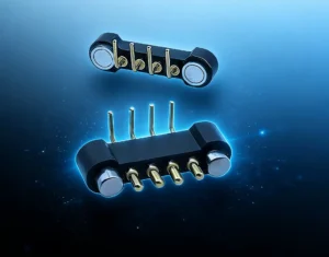
Reliable magnetic pogo pin connector design requires coordination between
mechanical alignment, pogo pin working stroke, mating-target geometry,
magnetic capture, seated retention, electrical load and environmental
exposure. Magnets can make mating easier, but they do not eliminate contact
wear, misalignment, side loading, contamination or electrical fault states.
Connector reliability should therefore be developed from defined failure
modes and verified through project-specific mechanical, electrical and
environmental validation.
What Does Magnetic Pogo Pin Connector Reliability Actually Mean?
Connector reliability is not the same as simply achieving electrical
continuity during the first prototype test.
A reliable magnetic pogo pin interface should continue to establish the
required electrical connection while operating within its approved
mechanical and environmental conditions.
Depending on the application, engineers may need to evaluate connection
stability across repeated mating, dimensional variation, user
misalignment, vibration, contamination, electrical load and temperature.
This means the useful engineering question is not:
“Can this magnetic connector make contact?”
A better question is:
“Which failure modes could prevent this interface from maintaining the
required electrical condition throughout the product lifecycle?”
Start with the Connector Failure Modes
| Failure Mode | Possible Cause | Primary Design Control |
|---|---|---|
| Intermittent Contact | Insufficient working stroke or unstable seating | Mechanical stop and tolerance-stack control |
| High Contact Resistance | Contamination, wear or insufficient contact force | Contact geometry, stroke and environmental validation |
| Bent or Damaged Pogo Pin | Excessive side loading or poor alignment | Mechanical guidance and structural load separation |
| Incomplete Mating | Offset, tilt or foreign debris | Housing geometry and mating-state detection |
| Unexpected Separation | Insufficient retention or external cable load | Retention and breakaway design |
| Excessive Wear | Sliding, contamination or over-compression | Controlled mating motion and lifecycle testing |
| Thermal Rise | Higher path resistance under electrical load | Voltage-drop and temperature-rise validation |
Reliability therefore comes from controlling several interacting failure
mechanisms rather than relying on one material, magnet or plating choice.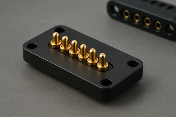
depends on working stroke, alignment, target geometry, electrical load
and project-specific validation.
Magnetic Capture Helps Alignment — But It Does Not Replace Mechanical Design
One advantage of a magnetic interface is that attraction can assist the
final approach between the two connector halves.

However, magnetic force should not be expected to correct every lateral,
angular or dimensional error.

A robust connector generally separates the mating process into different
mechanical functions.| Mating Function | Recommended Design Control |
|---|---|
| Initial Approach | User, robot or module positioning |
| Coarse Alignment | Housing geometry or guide features |
| Magnetic Capture | Magnet arrangement |
| Final Position | Mechanical datum surfaces |
| Pogo Pin Compression | Mechanical stop and tolerance stack |
| Seated Retention | Magnetic and housing structure |
This reduces the risk of forcing the pogo pin plunger to absorb large
alignment errors that should have been handled by the surrounding
mechanical structure.
Pogo Pins Should Not Be the Mechanical Alignment Feature
Spring-loaded contacts are primarily designed to provide compliant
electrical contact along their intended axis.

Excessive lateral force can increase friction, damage the plunger or create
uneven compression across a multi-pin array.

A preferred mechanical architecture transfers structural loads through the
connector housing and locating features rather than through the pogo pins.

A simplified load path is:


    Mating Module
    →
    Housing / Guide Features
    →
    Mechanical Stop
    →
    Host Structure
rather than:
    Mating Module
    →
    Pogo Pin Plunger
    →
    Internal Spring
    →
    PCB / Termination
Working Stroke Is One of the Most Important Reliability Parameters
Once the connector reaches its final seated condition, every pogo pin
should remain within its approved working-compression range.
A simplified relationship is:
S = Hfree - Hseatedwhere:
- S is actual pogo pin compression;
- Hfree is the installed free contact height;
- Hseated is the final mating height.
The complete tolerance stack can include pogo pin height, target position,
PCB mounting, housing dimensions and mechanical-stop variation.| Working Condition | Possible Reliability Effect |
|---|---|
| Insufficient Compression | Intermittent contact or unstable resistance |
| Approved Working Stroke | Intended contact-force and electrical condition |
| Excessive Compression | Spring bottoming, target wear or structural loading |
| Unequal Compression | Different electrical conditions across the contact array |
Total Travel Is Not the Same as Recommended Working Stroke
A pogo pin can have more available mechanical travel than should be used
during normal operation.

Designing the product around the maximum possible travel can increase
internal stress and make the connector more sensitive to dimensional
variation.

The final product should therefore use the recommended working stroke from
the approved pogo pin specification rather than treating total travel as
the normal operating range.
Magnetic Force Does Not Control Contact Force by Itself
The magnet pulls the mating halves together, while the pogo pin spring
creates contact force at the defined compression.

These forces interact mechanically, but they are not the same parameter.

A multi-pin connector also generates a total spring reaction force from the
compressed contact array.
A simplified relationship is:
Ftotal ≈ F1 + F2 + ... + Fn

The seated magnetic retention should therefore be sufficient for the
intended interface while accounting for contact spring force, module weight,
vibration and expected user or cable loads.
Capture Force, Retention and Breakaway Should Be Specified Separately
One magnetic-force number does not completely describe connector behavior.| Magnetic Requirement | Engineering Meaning |
|---|---|
| Capture Behavior | How attraction influences the connector during approach |
| Seated Retention | Force holding the fully seated halves together |
| Axial Separation | Force required for straight pull-off |
| Peel Separation | Behavior when separation begins from one edge |
| Off-Axis Load | Response to lateral or twisting force |
Zero-Force Release Is Not an Accurate Description
A magnetic connector can be designed for easier or controlled breakaway,
but physical separation still requires force.

Breakaway behavior depends on:- magnet geometry;
- seated retention;
- pull direction;
- cable angle;
- connector housing;
- device mass;
- surface friction.
For cable-based interfaces, peel release may behave very differently from
straight axial separation.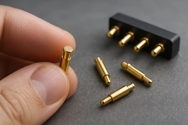
variation while magnets assist capture. Final position should still be
controlled by the mechanical interface.
Magnetic Pogo Pin Connectors Are Not Wear-Free
Switching from a deep insertion connector to a pogo pin interface changes
the mating mechanics, but it does not eliminate mechanical wear.
Wear can still come from:
- lateral sliding during capture;
- angled mating;
- vibration while connected;
- abrasive contamination;
- excessive working stroke;
- target-surface wear;
- powered mating or separation.
The useful design goal is controlled and repeatable contact motion rather
than “zero friction.”
Self-Wiping Does Not Mean Self-Cleaning
Some pogo pin tip and mating-target geometries may create limited relative
movement during compression.

This can disturb certain light surface films, but it should not be treated
as guaranteed cleaning.

Dust, fibers, oil, corrosion products and abrasive particles can still
interfere with the contact interface.

Representative contamination testing is therefore more meaningful than a
generic self-cleaning claim.
Contact Resistance Should Be Defined Under a Test Condition
A single contact-resistance value has limited engineering meaning unless
the measurement method is also defined.
Relevant conditions can include:
- working stroke;
- contact force;
- mating target;
- measurement current;
- temperature;
- contact cleanliness;
- measurement method.
Contact resistance may also change after repeated mating or environmental
exposure.
Evaluate the Complete Electrical Resistance Path
The pogo pin is only one resistance element inside the finished electrical
connection.
A simplified path can be represented as:
    Host PCB / Wire
    →
    Termination
    →
    Pogo Pin
    →
    Contact Interface
    →
    Mating Target
    →
    Device PCB / Wire
The complete resistance can be expressed as:
    Rpath =
    Rhost +
    Rtermination +
    Rpogo +
    Rinterface +
    Rtarget +
    Rdevice
The voltage drop is:
Vdrop = I × RpathThe resistive loss is:
Ploss = I² × Rpath

Higher-current applications should therefore be validated using the
complete electrical path and temperature-rise behavior.
Parallel Contacts Need Current-Sharing Validation
Multi-pin magnetic connectors sometimes place several contacts in parallel
for power or return.

Parallel contacts do not automatically carry equal current.
Current distribution can be affected by:
- working-stroke variation;
- contact-resistance variation;
- target flatness;
- connector tilt;
- PCB or busbar routing;
- termination resistance;
- contamination.
The current capability of the complete array should therefore be verified
rather than calculated by simply multiplying the rating of one contact.
Partial Mating Is a Reliability and Safety State
Magnetic attraction begins before the connector always reaches its final
seated position.

During this transition, individual contacts can engage at different times.| Partial-Mating Condition | Possible Effect |
|---|---|
| One Contact Touches First | Unexpected electrical sequence |
| Connector Is Tilted | Unequal pogo pin compression |
| Debris Prevents Full Seating | Unstable or high-resistance contact |
| Only Some Parallel Contacts Engage | Unequal current distribution |
| Connector Separates Under Load | Transient voltage or arcing |
Products with higher electrical power or sensitive electronics may require
detection, sequencing, current limiting or power gating before the interface
becomes fully energized.
Magnets Can Create a Metallic-Debris Failure Mode
Permanent magnets can attract ferromagnetic particles toward the mating
interface.

Depending on connector geometry, metallic debris may:- prevent full seating;
- change working stroke;
- scratch mating targets;
- bridge adjacent contacts;
- increase local resistance.
Cleaning access, insulation barriers, contact spacing and fault protection
should therefore be considered where metallic contamination is realistic.
Environmental Protection Is an Assembly-Level Requirement
A magnetic pogo pin connector can be incorporated into a sealed product,
but neither magnets nor pogo pins automatically establish an IP rating.
The environmental boundary may include:
- pogo pin feedthroughs;
- connector housing;
- housing-to-product joint;
- gaskets;
- insert molding or potting;
- PCB or wire termination;
- other enclosure openings.
Mated and unmated connector states can also require different validation.Material and Plating Selection Should Follow the Application
Spring materials, plunger materials and surface finishes influence
electrical and mechanical behavior, but one material stack is not optimal
for every magnetic pogo pin connector.
Material selection can depend on:
- working stroke;
- contact force;
- continuous and peak current;
- temperature;
- mating-cycle target;
- wear mechanism;
- corrosion environment;
- target material and finish.
Claims such as a specific copper alloy, plating thickness or mating life
should therefore be tied to the approved connector drawing and validation
record.
A Metal Housing Does Not Automatically Create EMI Immunity
Conductive housing material can contribute to an electromagnetic shielding
architecture, but the housing alone does not ensure EMI immunity.
EMC behavior can also depend on:
- housing electrical continuity;
- shield termination;
- chassis bonding;
- apertures and gaps;
- signal-return paths;
- contact layout;
- PCB routing;
- cable shielding;
- frequency range.
Likewise, a metal connector housing should not automatically be described
as a Faraday cage.
Pin Count Does Not Define Data Capability
A multi-pin magnetic pogo pin connector provides multiple conductive paths,
but the number of contacts alone does not establish support for a particular
signal protocol or data rate.

Signal capability can depend on contact geometry, reference paths, PCB
transitions, cable construction, crosstalk and complete-channel validation.
Mating Cycle Claims Need Defined Test Conditions
A generic mating-cycle number should not be treated as a universal property
of magnetic pogo pin connectors.
A meaningful lifecycle test should identify:
- connector revision;
- working stroke;
- mating target;
- mating speed;
- alignment condition;
- electrical load;
- environmental conditions;
- cleaning procedure;
- measurement intervals;
- electrical and mechanical failure criteria.
A cycle number measured under clean, unloaded bench conditions should not
automatically be transferred to a powered connector operating in a
contaminated or dynamic application.
Reliability Should Be Validated Against Defined Failure Criteria
| Validation Area | Recommended Evaluation |
|---|---|
| Working Stroke | Verify minimum, nominal and maximum compression |
| Alignment | Evaluate expected lateral and angular mating errors |
| Side Load | Confirm housing carries structural loading rather than pogo pins |
| Magnetic Capture | Evaluate approach and final seating separately |
| Retention / Breakaway | Measure defined axial and off-axis release conditions |
| Contact Resistance | Measure at defined stroke and target condition |
| Voltage Drop | Measure complete power path under load |
| Temperature Rise | Evaluate at intended electrical load and ambient condition |
| Partial Mating | Test tilted, offset and incomplete connection states |
| Contamination | Evaluate representative dust, oil, fibers or metallic debris |
| Repeated Mating | Monitor resistance, stroke, wear and magnetic behavior |
| Environmental Exposure | Evaluate the conditions required by the actual application |
How to Specify a Reliable Magnetic Pogo Pin Connector
| Parameter | Engineering Definition |
|---|---|
| Pin Count | Number of independent electrical paths |
| Pin Map | Power, return, control and signal allocation |
| Working Stroke | Minimum, nominal and maximum pogo pin compression |
| Contact Force | Specify at a defined working stroke |
| Mating Target | Dimensions, finish, flatness and structural support |
| Alignment Tolerance | Expected X, Y and angular mating variation |
| Capture Behavior | Magnetic response during approach |
| Seated Retention | Required holding force after complete mating |
| Breakaway Requirement | Desired separation behavior and pull direction |
| Electrical Conditions | Voltage, continuous current and peak current |
| Environment | Temperature, dust, moisture, sweat, oil or other exposure |
| Lifecycle Target | Required cycles and acceptance criteria |
Frequently Asked Questions
Are magnetic pogo pin connectors 100% reliable?
No connector should be described as universally 100% reliable.
Reliability depends on the application, working stroke, alignment,
electrical load, environment, lifecycle and complete system design.
Do magnets prevent pogo pin misalignment?
Magnets can assist final capture, but housing geometry and mechanical
datums should control final connector position and pogo pin compression.
Can magnetic pogo pins eliminate lateral stress?
Not automatically. Lateral loading should be minimized through mechanical
guidance and a load path that prevents the pogo pins from acting as
structural alignment features.
Are magnetic pogo pin connectors wear-free?
No. Pogo pins and mating targets can still experience wear from repeated
contact, sliding, vibration, contamination and excessive compression.
Are pogo pin contacts self-cleaning?
Some contact geometries may create limited wiping action, but this should
not be treated as guaranteed removal of dust, oil, corrosion or debris.
Does a magnetic connector have zero-force breakaway?
No. Separation always requires some force. The actual breakaway behavior
depends on magnet geometry, pull direction, housing design and the complete
product mechanics.
Can a metal housing eliminate EMI?
No. A conductive housing can contribute to shielding, but EMC performance
depends on the complete grounding, shielding, PCB, cable and enclosure
architecture.
Can a magnetic pogo pin connector last one million cycles?
A specific cycle-life claim is meaningful only when the connector revision,
working stroke, target, mating conditions, electrical load, environment
and acceptance criteria are defined and tested.
Does a magnetic pogo pin connector automatically support high-speed data?
No. Pin count and magnetic structure do not establish data capability.
Signal performance requires complete-channel electrical design and
validation.
What information is needed for a reliable custom magnetic connector?
Provide the Pin Map, voltage, current, working stroke, mating target,
alignment tolerance, retention and breakaway requirements, environmental
conditions, lifecycle target and available mechanical or PCB drawings.
Request a Magnetic Pogo Pin Connector Engineering Review
Explore

    custom magnetic connector solutions

for different pin counts, layouts and removable electrical interfaces.

Review

    pogo pin and spring-contact solutions

for project-specific board-level and device interfaces.

Learn more about CTP manufacturing and engineering capabilities on our

    About Us page
.

Submit the Pin Map, electrical requirements, working stroke, installation
space, mating conditions and project drawings through the

    Get Quote & Samples page
.


    CTP can review contact layout, pogo pin working stroke, mating targets,
    magnetic capture, seated retention, breakaway behavior and PCB, FPC or
    wire termination for custom magnetic connector projects. Final contact
    resistance, current capability, signal performance, environmental
    protection, lifecycle and system reliability depend on the approved
    connector design and project-specific validation.
CTP ENGINEERING PATHS
Choose the right path for your project
Move from application requirements to a connector pair, a data-capable cable assembly, or a charging cable configuration. Final specifications are confirmed against an approved drawing and project validation plan.
Magnetic Connectors
Connector geometry, pin layout, mechanical integration and OEM/ODM review.
Engineering overview → 02Magnetic Data Cables
Power and signal allocation, cable exit, interface selection and assembly review.
Cable engineering → 03Magnetic Charging Cables
Browse the complete cable catalog and shortlist a starting structure for customization.
View cable catalog →