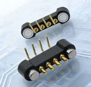
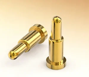
Industrial magnetic pogo pin selection should begin with the machine interface, not with a catalog photo or a preferred magnet grade. The connector must match the required current, signal type, mating frequency, working compression, docking tolerance, environmental exposure and production method.
A magnetic pogo pin connector combines two different systems:
- spring-loaded contacts that carry electrical current or signals;
- magnets that assist alignment and provide retention force.
These functions must be designed together, but they should not be confused. Stronger magnets do not increase the electrical current rating, and a larger pogo pin does not automatically correct poor docking alignment.
Select an industrial magnetic pogo pin connector by defining the circuit map, continuous and peak current, operating voltage, required stroke, spring force, total contact load, magnetic retention range, allowable misalignment, termination method and environmental conditions. The final selection should then be confirmed through tolerance, temperature, mating and contamination testing.
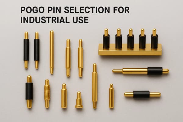
When Should Engineers Consider a Magnetic Pogo Pin Connector?
A magnetic pogo pin connector is most useful when the application requires repeated mating and benefits from assisted alignment or controlled breakaway.
Typical industrial applications include:
- AGV and AMR charging docks;
- robotic tool changers;
- automated inspection fixtures;
- removable sensor modules;
- portable industrial terminals;
- smart battery modules;
- industrial handheld equipment;
- service and programming interfaces;
- automated pallet systems.
A magnetic interface may not be necessary when the connection remains permanently installed, requires a standardized industrial connector or must withstand high structural loads without any possibility of separation.
Industrial Magnetic Pogo Pin Selection Workflow
A practical selection process can be divided into nine steps:
- define the application and mating behavior;
- create the electrical pin map;
- determine the current and voltage requirements;
- select the pogo pin working stroke and spring force;
- calculate the total spring load;
- define magnetic retention and breakaway force;
- select the mechanical layout and mounting method;
- review environmental and contamination risks;
- create the validation and acceptance plan.
Skipping one of these steps often leads to repeated sample revisions or a connector that performs correctly only under nominal laboratory conditions.
1. Define the Application Before Selecting the Contact
The same pogo pin may behave differently in a stationary charging dock, a moving robot arm and a handheld industrial device.
Start by defining:
- what two assemblies are being connected;
- whether mating is manual or automated;
- whether the connection remains engaged during operation;
- whether controlled breakaway is required;
- how often the connector mates per day;
- whether power is present during mating;
- whether the connector is exposed when disconnected;
- whether the contact module must be replaceable.
| Application condition | Selection impact |
|---|---|
| Automated docking | Requires defined capture range, mechanical guides and repeatable final compression. |
| Manual charging | Requires suitable user force, orientation control and exposed-contact protection. |
| Connection remains during machine movement | May require mechanical retention beyond magnetic force. |
| Frequent tool replacement | Requires accessible and replaceable contact modules. |
| Harsh contamination | Requires recessed contacts, cleaning access and fault protection. |
2. Create the Electrical Pin Map
The connector pin count should be determined by the required circuits rather than by the appearance of an existing connector.
Possible circuits include:
- main power;
- power ground;
- control voltage;
- analog sensor signals;
- digital inputs and outputs;
- communication signals;
- module identification;
- temperature sensing;
- connector detection;
- protective or functional ground.
Example industrial pin allocation
| Contact group | Possible circuit | Selection priority |
|---|---|---|
| Power contacts | Main supply or charging current. | Low resistance, temperature rise and sufficient spacing. |
| Power return | Main current return. | Return capacity should match the outgoing path. |
| Detection contact | Confirms correct mating. | May engage before the main power path. |
| Identification contact | Identifies the connected tool or module. | Should be protected from incorrect offset mating. |
| Signal contacts | Control, sensor or communication. | Requires suitable ground reference and spacing from power. |
Separate power and sensitive signals
Where space allows, high-current circuits should be separated from sensitive analog or communication contacts. Ground contacts may be placed between groups to improve return-path control and reduce coupling.
For high-speed industrial protocols, continuity alone is not enough. The connector-head PCB, cable, signal return and shielding must be designed for the specific protocol.
3. Determine Current and Voltage Requirements
Industrial pogo pin current capability should be evaluated through the complete path, not only through the pogo pin itself.
The current path may include:
- the pogo pin;
- mating pad;
- connector-head PCB;
- wire or cable;
- solder joint or crimp;
- device-side PCB or busbar;
- switching and protection components.
Electrical requirements to define
- continuous current per circuit;
- peak current and duration;
- operating voltage;
- acceptable voltage drop;
- maximum temperature rise;
- duty cycle;
- hot-plugging requirement;
- fault-current capability;
- required insulation spacing.
A connector may carry a short current pulse without excessive heating but be unsuitable for the same current continuously.
Parallel power contacts
Multiple pogo pins can be connected in parallel, but current does not always divide equally.
Current sharing is affected by:
- contact resistance;
- working compression;
- installed height;
- PCB routing length;
- mating-pad condition;
- local temperature.
Parallel-contact capacity should therefore be confirmed through branch-current and temperature testing rather than simple multiplication.
4. Select the Pogo Pin Working Stroke
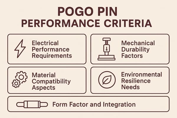
The working stroke is the amount of compression used during normal mating. It should not be confused with total mechanical travel.
The required stroke depends on:
- connector housing tolerance;
- PCB position tolerance;
- mating-pad height;
- robot or fixture repeatability;
- enclosure deformation;
- expected wear;
- thermal expansion.
Compression conditions to check
| Condition | Risk | Required action |
|---|---|---|
| Too little compression | Insufficient contact force and intermittent continuity. | Adjust installed height, mating distance or selected stroke. |
| Correct compression | Contact operates inside the approved force and travel range. | Control through datums, guides and mechanical stops. |
| Excessive compression | Bottoming, spring damage, housing stress or PCB deformation. | Add a mechanical stop and review the worst-case tolerance. |
| Uneven compression | Different resistance and force across the array. | Improve flatness, alignment and installed-height control. |
Calculate the complete tolerance stack
The minimum and maximum compression should include all supplier-side and customer-side dimensions. A connector that works at the nominal CAD position may still fail at the tolerance limits.
5. Select Spring Force and Calculate Total Contact Load
Each pogo pin creates an axial spring force at its working position. In a multi-pin connector, the forces add together.
Total spring load influences:
- the required magnetic retention;
- robot or actuator force;
- housing deformation;
- PCB loading;
- user separation force;
- gasket compression.
For example, a connector with many signal contacts may create a substantial total load even though each individual pin has a moderate spring force.
Spring force should be selected according to:
- required contact stability;
- mating-pad material;
- plunger-tip geometry;
- working stroke;
- contact count;
- housing strength;
- mating mechanism;
- expected vibration.
Higher force may improve contact pressure but can also increase wear, mating load and housing stress.
6. Define Magnetic Retention and Breakaway Force
Magnetic force should be specified as an acceptable range rather than only as a maximum attraction value.
The minimum retention should overcome:
- the total pogo pin spring load;
- cable weight;
- normal vibration;
- gasket or seal force;
- expected operating movement.
The maximum retention should remain compatible with:
- required breakaway behavior;
- robot separation force;
- user handling;
- housing strength;
- device mass;
- maintenance requirements.
Do not select magnets by grade alone
Magnetic holding force depends on more than the magnet grade. It is also affected by:
- magnet dimensions;
- number of magnets;
- air gap;
- steel or magnetic circuit components;
- housing thickness;
- magnet position;
- mating orientation;
- temperature.
A particular magnet grade is not automatically required for every industrial connector.
7. Decide Whether Magnetic Retention Is Enough
Some industrial interfaces need magnets only for final alignment. Other interfaces may use magnetic force as the main retention mechanism.
Independent mechanical locking should be considered when:
- the module remains connected during high-speed machine movement;
- the connected tool is heavy;
- the cable applies continuous force;
- unexpected separation could damage equipment;
- the connector carries a safety-related function;
- the application cannot tolerate breakaway.
In these cases, magnets may guide the connector while a latch, rail, screw or mechanical lock carries the operating load.
8. Select the Contact Layout
The arrangement of the pogo pins affects electrical safety, alignment, current sharing and offset-mating behavior.
Linear layout
Linear contact arrays are compact and easy to integrate into narrow housings. They may be suitable for magnetic cables, rails and elongated docking surfaces.
Circular layout
Circular arrangements may support rotational symmetry or compact module docking. Anti-rotation features may still be required when the pin map is not rotationally symmetric.
Multi-row layout
Multi-row layouts increase circuit density but require tighter control of flatness, compression and contact spacing.
Asymmetric layout
Asymmetry can help prevent reverse mating and reduce the risk of an incorrect pin-to-pad connection.
Review offset mating
The design should be checked under:
- one-pin lateral offset;
- reverse orientation;
- angular mating;
- partial engagement;
- mating with the wrong module.
Incorrect mating should not connect main power to a signal or ground circuit.
9. Select Pin Pitch and Contact Spacing
Smaller pitch allows more contacts in a limited area, but it also reduces spacing between conductive surfaces.
Pin pitch should consider:
- operating voltage;
- contamination level;
- expected condensation;
- mating-pad diameter;
- allowable positional error;
- manufacturing tolerance;
- signal coupling;
- cleaning access.
A high-density layout that works in a clean laboratory may become unreliable in an industrial environment containing oil, conductive dust or moisture.
10. Choose the Pogo Pin Tip Geometry
The plunger-tip geometry affects contact area, wiping behavior, mating-pad wear and contamination tolerance.
Possible tip types include:
- flat;
- rounded;
- conical;
- crown;
- serrated;
- custom-profile tips.
| Tip geometry | Potential advantage | Selection concern |
|---|---|---|
| Flat | Broad contact area on a flat pad. | May be more sensitive to surface contamination. |
| Rounded | Tolerates moderate angular variation. | Creates a smaller initial contact area. |
| Crown or serrated | Can engage uneven or contaminated surfaces. | May increase pad wear or marking. |
| Conical | Creates concentrated contact pressure. | Requires a suitable mating-pad material and thickness. |
The tip should be selected together with the mating pad, not independently.
11. Select the Mounting and Termination Method
Industrial magnetic pogo pin connectors may connect to the system through:
- SMT soldering;
- through-hole soldering;
- press-fit installation;
- wire soldering;
- crimped wires;
- FPC;
- connector-head PCB;
- overmolded cable assemblies.
SMT-mounted connector
Suitable for automated PCB assembly, but coplanarity, placement support and reflow compatibility must be controlled.
Through-hole connector
Can provide stronger PCB retention but requires suitable hole dimensions, soldering control and cleaning.
Wire or cable termination
Provides routing flexibility, but strain relief, wire gauge, solder joints and cable movement become part of the reliability system.
FPC termination
Useful for compact or movable interfaces, but bend radius, reinforcement and strain must be controlled.
The termination method should fit the customer’s final assembly process rather than only the connector supplier’s preferred process.
12. Review the Environmental Conditions
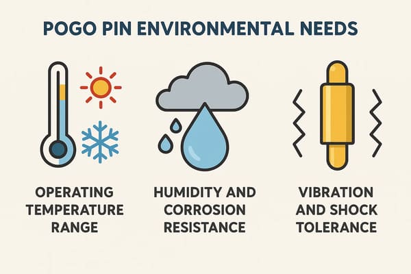
Environmental requirements may include:
- operating temperature;
- storage temperature;
- humidity;
- condensation;
- water exposure;
- oil and coolant;
- salt or sweat;
- dust;
- metallic particles;
- cleaning chemicals;
- vibration and shock.
Magnets and metallic debris
Magnetic connectors require specific attention to iron-containing debris. Particles attracted to the mating surface may bridge contacts, restrict pogo pin compression or scratch the plating.
Possible controls include:
- recessed contacts;
- insulating barriers;
- protective covers;
- cleaning access;
- debris inspection before power enable;
- fault-current protection.
Ingress protection
An industrial magnetic connector can be integrated into a sealed system, but a particular IP rating applies only to the tested assembled product.
Ingress protection depends on:
- housing joints;
- gasket design;
- insert molding or potting;
- cable entry;
- drainage;
- the mated and unmated condition.
13. Select Materials and Plating from the Application
Pogo pin materials influence spring behavior, conductivity, wear and corrosion resistance. However, there is no single material combination that is best for every industrial application.
Selection should consider:
- electrical current;
- contact force;
- mating-cycle target;
- operating temperature;
- humidity and chemical exposure;
- tip and pad materials;
- expected sliding movement;
- manufacturing process;
- cost and availability.
Plating cannot correct incorrect compression, side loading or poor mechanical alignment. Mechanical conditions should be defined before changing to a thicker or more expensive surface finish.
14. Define Contact Sequencing and Hot-Plug Behavior
During mating, not every contact necessarily engages at the same time. Industrial connectors carrying power and control circuits may require a defined sequence.
Possible sequences include:
- ground before power;
- detection before power;
- identification before machine enable;
- pre-charge before main current;
- power removal before physical separation.
Sequencing can be created through different pin lengths, pad heights or electronic control.
The sequence should be checked during:
- straight mating;
- angled mating;
- partial mating;
- slow engagement;
- rapid engagement;
- contaminated contact conditions.
15. Select Between Standard, Semi-Custom and Full-Custom Designs
| Design route | Suitable condition | Typical customization |
|---|---|---|
| Standard connector | Existing dimensions and performance match the device. | Cable length, color, pin map or marking. |
| Semi-custom connector | Existing pogo pin and magnet platforms can be reused. | Housing, pin arrangement, mounting and cable exit. |
| Full-custom connector | Current, stroke, size or environment falls outside existing platforms. | Pogo pin, housing, magnet system, tooling and assembly process. |
A full-custom design should be selected only when the technical requirements justify the additional tooling, validation and supply-chain complexity.
Industrial Magnetic Pogo Pin Selection Matrix
| Project requirement | Selection direction |
|---|---|
| Simple low-voltage charging | Evaluate a 2-pin power-and-ground layout. |
| Power plus mating detection | Add a dedicated detection or identification contact. |
| High current in limited space | Evaluate larger contacts or parallel power pins with thermal testing. |
| High positional variation | Use mechanical guides, floating mounts and suitable working stroke. |
| Controlled breakaway required | Define a magnetic retention-force window. |
| Heavy tool remains connected during operation | Use magnetic alignment with independent mechanical locking. |
| Conductive dust or metal chips | Use recessed contacts, cleaning access and fault protection, or consider a different connector. |
| Standardized industrial communication | Confirm protocol-level performance or retain a standardized connector. |
Validation Plan Before Final Selection
The connector should be evaluated under realistic assembled conditions.
| Validation area | Recommended evaluation |
|---|---|
| Dimensions | Installed height, pin pitch, flatness, magnet position and mating distance. |
| Compression | Minimum, nominal and maximum working stroke across all contacts. |
| Electrical | Continuity, contact resistance, voltage drop and insulation. |
| Thermal | Temperature rise under continuous and peak load. |
| Magnetic | Retention force, breakaway force and polarity verification. |
| Mating | Straight, offset, angled and partial mating. |
| Durability | Repeated mating followed by resistance, force and surface inspection. |
| Dynamic | Live continuity during machine movement, vibration and cable loading. |
| Environment | Dust, moisture, oil, metal particles, chemicals and cleaning procedures. |
What to Include in a Connector Specification Sheet
A useful specification or RFQ should include:
- application and equipment type;
- connector location;
- manual or automated mating;
- pin count and pin assignment;
- continuous and peak current;
- operating voltage;
- signal protocol and data rate;
- available connector dimensions;
- required pin pitch;
- working stroke;
- preferred spring-force range;
- required magnetic retention or breakaway range;
- mating direction;
- allowable lateral and angular misalignment;
- mounting and termination method;
- environmental exposure;
- mating-cycle target;
- prototype quantity;
- production forecast;
- required tests and acceptance criteria;
- 2D drawings, 3D files and PCB information.
Clearly identify which values are fixed requirements and which remain open to engineering recommendation.
Common Industrial Magnetic Pogo Pin Selection Mistakes
Selecting by external size only
Two connectors with similar dimensions may have different stroke, force, current path and mating behavior.
Choosing the strongest available magnet
Excessive attraction can increase separation force, housing stress and metallic-debris collection.
Ignoring total spring load
The combined force of many pogo pins may exceed the magnetic retention or robot docking capability.
Using current per pin as the complete connector rating
The cable, PCB, termination, mating pads and thermal environment must also support the load.
Assuming more pins always provide more current
Parallel contacts may share current unevenly.
Selecting plating before correcting the mechanics
Expensive plating does not fix side loading, incorrect compression or poor alignment.
Assuming magnetic alignment eliminates mechanical guides
Magnets normally assist final alignment. Large positional and angular errors still require mechanical guidance.
Ignoring the unmated condition
Exposed contacts may be affected by contamination, accidental shorting or unauthorized contact.
When an Industrial Magnetic Connector May Not Be Suitable
A conventional connector may be a better option when:
- the interface must remain positively locked under high force;
- a standardized industrial connector is mandatory;
- the environment contains uncontrolled metallic debris;
- the connection remains permanent;
- the system cannot keep exposed contacts de-energized;
- the available area cannot provide suitable electrical spacing;
- third-party cable compatibility is required;
- magnetic fields are incompatible with nearby components or processes.
Frequently Asked Questions
How do I select an industrial magnetic pogo pin?
Start with the application, pin map, current, voltage, working stroke, total spring load, retention-force range, mounting method and environment. Then confirm the selection through assembled testing.
Is a magnetic pogo pin connector more reliable than a standard pogo pin connector?
It can simplify alignment and retention in suitable applications. Reliability still depends on mechanical guides, compression, contamination control and the complete electrical path.
How much working stroke should a pogo pin use?
The required stroke depends on the full tolerance stack and selected pogo pin structure. The pin should remain within its approved working range at both minimum and maximum assembled conditions.
How is magnetic retention force selected?
The minimum force should overcome total spring load and normal external forces. The maximum should remain compatible with breakaway, housing strength and maintenance requirements.
Can multiple pogo pins be connected in parallel for higher current?
Yes, but current sharing, voltage drop and temperature should be measured. Equal current distribution should not be assumed.
What pin count should a magnetic charging connector use?
Two pins may support basic power and ground. Additional contacts may be required for detection, identification, temperature sensing, control or data.
Does a magnetic connector require a mechanical guide?
Usually yes. Mechanical guides control large positional errors and protect the pogo pins from side loading, while magnets assist final alignment.
Can an industrial magnetic pogo pin connector be waterproof?
It can be integrated into a sealed assembly, but the final protection level depends on the complete housing, gasket, molding, cable entry and test conditions.
Conclusion
Industrial magnetic pogo pin selection should be based on the complete electrical and mechanical interface rather than one isolated specification.
Engineers should first define the application and circuit map, then select the working stroke, spring force, contact layout, magnetic retention and mounting method. The final design must account for total spring load, offset mating, environmental contamination, hot-plug behavior and the customer-side tolerance stack.
A magnetic connector is most effective when each element has a clear role: mechanical guides control large positional errors, magnets assist final alignment and retention, pogo pins provide axial electrical contact, and the control system manages detection and power sequencing.
CTP supports custom development of individual pogo pins, pogo pin connector assemblies, magnetic pogo pin connectors and magnetic cable assemblies.
For an industrial connector project, submit the pin map, current, voltage, available space, working stroke, docking tolerance, retention requirement and environmental conditions through our Get a Quote & Samples page. The pogo pin, magnetic structure and mounting interface can then be evaluated together.