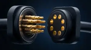
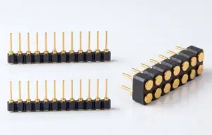
Moving a magnetic pogo pin connector from prototype to mass production requires more than approving a functional sample. The product drawing, material stack, working stroke, spring force, magnetic force, contact resistance, assembly process, measurement method, traceability and change-control rules must all be converted into repeatable production controls.
A successful engineering sample does not automatically prove that a magnetic pogo pin connector is ready for mass production. Prototype parts may be assembled by experienced technicians, adjusted individually or produced with temporary tooling. Mass production introduces different risks, including material-lot variation, tooling wear, fixture variation, operator differences, plating-process changes and measurement-system error.
The objective of production readiness is not to reproduce one perfect sample. It is to establish a controlled process that repeatedly produces connector assemblies within the approved electrical, mechanical and dimensional limits.
This guide explains how engineers can apply Design for Manufacturing, commonly called DFM, to move a custom magnetic pogo pin connector from concept samples through pilot production and into controlled volume manufacturing.
What Does Mass-Production Readiness Mean?
A connector is production-ready when the product definition, manufacturing process and inspection system are sufficiently controlled to support repeatable output.
This normally requires:
- An approved product drawing and revision
- A controlled bill of materials
- Defined critical-to-quality characteristics
- Approved manufacturing tooling and fixtures
- Documented process parameters
- Qualified measurement methods
- Pilot-production evidence
- Defined acceptance criteria
- Lot and material traceability
- A reaction plan for abnormal results
- Engineering change-control requirements
The amount of documentation depends on the customer, industry and product risk. A simple consumer charging interface may require a different approval package from a medical, automotive or safety-related device.
Prototype Success and Production Readiness Are Different
| Prototype Stage | Mass-Production Stage |
|---|---|
| Small quantity | Repeated production lots |
| Manual adjustment may be possible | Adjustment should be minimized and controlled |
| Experienced engineers may assemble each unit | Standardized work instructions and fixtures are required |
| Temporary tooling may be used | Production tooling must maintain dimensions over time |
| Parts may come from selected samples | Normal supplier and material-lot variation must be represented |
| Functional confirmation is the priority | Capability, repeatability, throughput and traceability are also required |
| Measurements may be performed by the design team | Production inspection methods must be documented and repeatable |
A connector that performs correctly after manual sorting or adjustment is not yet a stable production design.
Step 1: Freeze the Product Definition
Mass-production preparation should begin with a controlled product definition.
The approved package should identify:
- Connector part number
- Drawing revision
- Pin Map
- Electrical functions
- Mechanical envelope
- PCB, FPC, cable or wire interface
- Magnet arrangement and polarity
- Housing and mechanical-stop structure
- Materials and surface finishes
- Working-stroke window
- Spring-force requirements
- Magnetic holding and release requirements
- Inspection and validation criteria
Unresolved items should be recorded rather than left as informal assumptions.
Examples of incomplete specifications include:
- “Strong magnet”
- “Low resistance”
- “Gold plated”
- “Waterproof structure”
- “High-current pogo pins”
- “Suitable for repeated use”
These statements must be converted into measurable requirements before production release.
Step 2: Confirm the Required Supply Scope
The manufacturing process depends on whether the customer is purchasing:
- Individual pogo pins
- A pogo pin connector assembly
- A magnetic connector component
- A magnetic cable assembly
- A connector with PCB or FPC
- An overmolded magnetic cable
- An integrated magnetic module
A complete magnetic cable assembly may include additional production processes that are not present in a connector-only project:
- Wire cutting and stripping
- Crimping, soldering or welding
- PCB assembly
- Cable electrical testing
- Strain-relief assembly
- Overmolding
- Final connector alignment
- Appearance and dimensional inspection
The drawing, bill of materials and process flow should cover the complete requested supply scope.
Step 3: Conduct a Connector DFM Review
A DFM review evaluates whether the approved function can be produced consistently using practical materials, tooling, assembly methods and inspection systems.
Pogo Pin DFM
Review:
- Plunger diameter and tip geometry
- Barrel geometry and internal guidance
- Spring dimensions and force tolerance
- Free-height tolerance
- Total travel and working stroke
- Termination structure
- Plating coverage
- Assembly access
- Risk of plunger sticking or side loading
Housing DFM
Review:
- Pin pitch and hole position
- Connector flatness
- Wall thickness
- Material shrinkage
- Mold-release direction
- Insert retention
- Mechanical-stop dimensions
- Assembly datum structure
- Inspection access
Magnet DFM
Review:
- Magnet dimensions and tolerance
- Polarity arrangement
- Coating
- Assembly direction
- Adhesive or mechanical retention
- Magnet-position tolerance
- Assembled air gap
- Risk of reversed installation
PCB and Cable DFM
Review:
- PCB pad dimensions
- Solder-joint access
- Trace width and current path
- Wire gauge
- Cable conductor arrangement
- Stripping and termination length
- Strain-relief structure
- Overmolding flow and support
- Test-point access
Step 4: Build a Tolerance Stack
The installed pogo pin compression is determined by the complete assembly, not only by the pogo pin drawing.
The tolerance stack may contain:
- Pogo pin free height
- Pogo pin installed height
- Housing height
- PCB thickness
- Target-pad position
- Magnet position
- Mechanical-stop position
- Adhesive or overmolding thickness
- Seal compression
- Housing and PCB flatness
Calculate the following conditions:
| Assembly Condition | Required Confirmation |
|---|---|
| Minimum compression | Every required pin maintains sufficient contact force and electrical stability |
| Nominal compression | The connector operates at its intended design point |
| Maximum compression | No pin reaches an unintended mechanical limit or overloads the structure |
| Uneven compression | Housing or PCB variation does not cause unacceptable channel imbalance |
Production drawings should use functional datums that match how the connector is assembled and measured.
Step 5: Identify Critical-to-Quality Characteristics
Not every dimension or inspection item has the same effect on product function.
Critical-to-quality characteristics, often abbreviated as CTQs, are features that directly influence electrical performance, assembly, safety, reliability or customer use.
Typical magnetic pogo pin connector CTQs may include:
- Pogo pin free height
- Working height after assembly
- Spring force at a defined stroke
- Pin-to-pin position
- Connector flatness
- Magnet position and polarity
- Magnetic holding force
- Release or breakaway force
- Initial contact resistance
- Voltage drop under load
- Temperature rise
- Insulation between adjacent contacts
- Cable termination integrity
- Strain-relief performance
- Seal or insert retention
Each CTQ should link to:
- A drawing or specification requirement
- A measurement method
- An inspection frequency
- A sampling or full-inspection rule
- A reaction plan
- A retained record
Example CTQ Control Matrix
| CTQ | Why It Matters | Possible Control Method | Reaction to Failure |
|---|---|---|---|
| Pogo pin free height | Affects installed working stroke | Dimensional gauge or optical measurement | Contain the lot and investigate assembly or component variation |
| Spring force | Affects contact pressure and total connector load | Force measurement at a defined stroke | Verify spring lot, assembly condition and measurement system |
| Connector flatness | Affects pin-to-pin compression consistency | Fixture, optical system or coordinate measurement | Review housing molding, PCB support and assembly fixture |
| Magnet polarity | Affects mating orientation and holding behavior | Polarity fixture or magnetic inspection | Stop production and segregate affected assemblies |
| Contact resistance | Affects voltage drop, heat and signal stability | Defined two-wire or four-wire method | Isolate plating, stroke, contamination and termination causes |
| Cable pull strength | Affects field durability | Sampling pull test in a defined direction | Review termination, strain relief and overmolding process |
Step 6: Define the Manufacturing Process Flow
The process flow should represent the actual production sequence.
A magnetic connector assembly may include:
- Incoming material inspection
- Pogo pin component manufacturing or receipt
- Plating verification
- Housing molding or machining
- Magnet inspection
- Pogo pin insertion
- Magnet installation
- Adhesive curing or mechanical retention
- PCB, FPC, wire or cable termination
- Soldering, welding or crimping
- Housing assembly
- Overmolding or sealing
- Electrical testing
- Mechanical-force inspection
- Appearance inspection
- Cleaning and packaging
- Lot release and traceability recording
Each step should identify:
- Process input
- Equipment or tooling
- Controlled parameter
- Inspection method
- Responsible operation
- Output record
- Abnormal-condition reaction
Step 7: Conduct a Process Risk Review
Process risks should be evaluated before pilot production.
Typical magnetic connector process risks include:
- Wrong pogo pin installed
- Pogo pin inserted to the wrong height
- Pin damaged during pressing
- Spring or plunger contamination
- Incorrect magnet polarity
- Magnet positioned at the wrong depth
- Insufficient adhesive
- Adhesive entering the contact area
- Solder or flux entering the moving barrel
- Wire connected to the wrong Pin Map position
- Unequal overmolding pressure
- Connector housing deformation
- Incorrect test-fixture contact
- Mixed material or plating lots
Risk controls may include:
- Mechanical poka-yoke features
- Polarity-detection fixtures
- Barcode or material-lot verification
- Controlled press depth
- Automated vision inspection
- Dedicated fixture nests
- Electrical Pin Map testing
- Controlled adhesive dispensing
- Process alarms and interlocks
Step 8: Confirm the Measurement System
A production measurement must be repeatable enough to distinguish real product variation from inspection variation.
Before using a gauge or tester for release decisions, confirm:
- Measurement range
- Resolution
- Calibration status
- Fixture alignment
- Part positioning method
- Operator instructions
- Environmental sensitivity
- Repeatability
- Reproducibility between operators or stations
Measurement-system analysis may be appropriate for important CTQs such as:
- Spring force
- Magnetic holding force
- Connector height
- Contact resistance
- Pin position
- Housing flatness
A measurement method that produces different results depending on the operator, contact location or fixture pressure should not be used as the sole basis for product acceptance.
Contact Resistance Measurement Requires Controlled Conditions
Low-resistance measurements can be affected by:
- Test-lead resistance
- Probe location
- Fixture contact force
- Pogo pin compression
- Temperature
- Measurement current
- Contact stabilization time
Where appropriate, a four-wire Kelvin method can help separate lead and fixture resistance from the contact measurement.
The inspection specification should define:
- Measurement points
- Test current
- Working stroke
- Sample condition
- Maximum permitted value
- Whether the value applies to one contact or the complete path
Force Measurement Requires Controlled Geometry
Spring force and magnetic force should be measured separately.
For pogo pin spring-force measurement, define:
- Compression stroke
- Compression speed
- Axial alignment
- Force-gauge resolution
- Pin or connector assembly state
For magnetic-force measurement, define:
- Assembled air gap
- Pull direction
- Pull speed
- Pogo pins installed or removed
- Seal installed or removed
- Peak force or force-displacement requirement
A magnet-only pull test does not represent the net retention force of a completed connector containing compressed pogo pins and seals.
Step 9: Run a Representative Pilot Build
Pilot production should use the intended:
- Production materials
- Production tooling
- Production equipment
- Production fixtures
- Work instructions
- Inspection methods
- Operators or normal production staffing
The pilot build should not be produced entirely through engineering rework or manual adjustment.
The objectives include:
- Confirming process sequence
- Identifying assembly bottlenecks
- Measuring CTQ variation
- Evaluating tooling repeatability
- Confirming production test time
- Reviewing yield and defect categories
- Verifying traceability
- Confirming packaging and handling
Sample quantities and capability criteria should be agreed according to customer requirements, process risk and expected production volume rather than copied from a universal template.
Step 10: Review Process Capability
Process capability analysis can help determine whether a stable process has sufficient margin relative to the approved specification limits.
Suitable characteristics may include:
- Connector height
- Pin position
- Housing flatness
- Spring force
- Magnet position
- Magnetic holding force
- Contact resistance
Before calculating capability, confirm that:
- The measurement system is suitable
- The process is sufficiently stable
- The data represent normal production
- The specification limits are engineering limits rather than arbitrary inspection limits
- The selected statistical method is appropriate for the data distribution
A capability value should not replace engineering review. A process can appear statistically capable while still using the wrong product specification or measurement method.
Step 11: Establish the Production Control Plan
The production control plan should connect process risks and CTQs to routine controls.
| Process Stage | Potential Control |
|---|---|
| Incoming pogo pins | Part number, dimensions, free height, force and material-lot verification |
| Incoming magnets | Dimensions, coating, polarity and magnetic-force sampling |
| Housing production | Critical dimensions, flatness and molding-process parameters |
| Pogo pin assembly | Insertion height, retention and damage inspection |
| Magnet assembly | Polarity, position, adhesive amount and retention |
| Wire or PCB termination | Pin Map, soldering or welding parameters and electrical continuity |
| Final assembly | Connector height, flatness, magnetic mating and appearance |
| Electrical test | Continuity, short circuit, resistance or voltage drop as required |
| Packaging | Contact protection, magnet separation, label and lot traceability |
The control plan should specify what happens when a result is outside the requirement. Recording a failure without a containment and escalation rule is not a complete control.
100% Inspection Does Not Replace Process Control
Full inspection can be useful for selected characteristics such as:
- Electrical continuity
- Short-circuit detection
- Magnet polarity
- Pin Map verification
- Critical appearance defects
However, 100% inspection does not automatically prevent:
- Measurement-system error
- Progressive tooling wear
- Material changes
- Latent soldering defects
- Plating variation
- Spring-force drift
- Environmental durability problems
Destructive tests such as cable pull, sectioning or selected environmental tests are normally controlled through project-defined sampling rather than testing every product.
Step 12: Control Materials and Plating
The production bill of materials should distinguish:
- Plunger material
- Barrel or base material
- Spring material
- Underplate
- Contact finish
- Termination finish
- Housing resin
- Magnet material and coating
- Adhesive
- Wire and cable materials
Where plating is critical, control may include:
- Approved plating process
- Plating thickness or approved range
- Surface coverage
- Supplier lot traceability
- Inspection or certificate requirements
- Change-notification rules
A visual gold color check does not prove the complete plating stack or its thickness.
Step 13: Control Soldering and Assembly Cleanliness
Connector electrical performance can be affected by assembly residue and contamination.
Potential risks include:
- Flux entering the pogo pin barrel
- Solder wicking into a moving contact
- Adhesive contaminating the target surface
- Particles trapped around magnets
- Cleaning fluid remaining inside a recess
- Overmolding pressure moving the connector
The process should define:
- Soldering or welding parameters
- Fixture support
- Flux and cleaning controls
- Connector orientation during assembly
- Post-process inspection
- Contact protection during handling
Step 14: Establish Traceability
Traceability allows the manufacturer and customer to connect a finished connector to its production history.
Depending on project requirements, the record may include:
- Finished-product lot
- Production date and line
- Drawing revision
- Pogo pin lot
- Magnet lot
- Housing material lot
- Plating lot
- Cable or wire lot
- Inspection station
- Key test results
- Operator or equipment record
Traceability depth should reflect product risk, customer requirements and the ability to contain a suspected production issue.
Retain Reference Samples
Reference samples may include:
- Approved engineering sample
- Golden sample
- Limit samples for appearance
- Pilot-production samples
- First-off and last-off tooling samples
- Samples from major engineering revisions
A reference sample should not replace the drawing. Samples can age, become damaged or fail to represent all measurable requirements.
Step 15: Use a Controlled Launch Period
During initial production, additional monitoring may be appropriate for CTQs or known process risks.
A controlled launch may include:
- Increased inspection frequency
- Additional dimensional checks
- Expanded electrical testing
- Review of every defect category
- Daily process-data review
- Tooling and fixture verification
- Rapid escalation rules
The exit criteria should be defined in advance. Additional inspection should not continue indefinitely without reviewing whether the process itself has become stable.
Step 16: Control Engineering and Process Changes
Production approval applies to a defined product and process state.
Changes that may require review or partial revalidation include:
- Changing pogo pin construction
- Changing spring material or force
- Changing base material or plating
- Changing the magnet or coating
- Changing housing resin
- Changing adhesive
- Changing wire gauge or cable supplier
- Changing PCB finish
- Changing molds, tools or fixtures
- Changing production equipment
- Moving production to another facility or line
- Changing inspection equipment
- Changing the product drawing
The review should determine:
- Which product requirements are affected
- Which process risks are introduced
- Which inspections must be repeated
- Whether customer approval is required
- How old and new material will be separated
Recommended Production-Release Package
The required package depends on the customer and industry, but may include:
| Document | Purpose |
|---|---|
| Approved drawing | Defines the product and acceptance requirements |
| Bill of materials | Defines controlled materials and components |
| Process flow | Shows the manufacturing sequence |
| Process risk analysis | Identifies potential manufacturing failures and controls |
| Control plan | Defines routine inspections and reaction rules |
| Measurement-system records | Supports confidence in CTQ measurements |
| Dimensional report | Confirms drawing characteristics |
| Material and plating evidence | Confirms specified material stack |
| Electrical and mechanical results | Confirms required functional performance |
| Capability or pilot data | Shows production variation under representative conditions |
| Packaging specification | Protects contacts, magnets and traceability during shipment |
| Change-control agreement | Defines approval requirements for future changes |
Common Mass-Production Mistakes
| Mistake | Possible Consequence | Better Approach |
|---|---|---|
| Approving only one functional sample | Normal production variation remains unknown | Use pilot lots produced with intended materials and tooling |
| Leaving force and resistance as descriptive claims | Production cannot inspect them consistently | Define conditions, limits and measurement methods |
| Ignoring the measurement system | Good parts may fail inspection and bad parts may pass | Confirm fixture, resolution, repeatability and reproducibility |
| Using 100% inspection as the only quality strategy | Process drift and latent failures remain undetected | Combine process controls, sampling and suitable final inspection |
| Not controlling magnet polarity | Incorrect mating behavior or assembly rejection | Use polarity poka-yoke and documented inspection |
| Not controlling the complete tolerance stack | Pogo pins operate outside their approved stroke | Calculate minimum, nominal and maximum assembly conditions |
| Changing plating or materials without review | Resistance, wear or assembly behavior may change | Use formal change control and affected-item revalidation |
| Testing only loose connector components | PCB, cable and housing effects are missed | Test the complete supplied assembly and final installation where required |
| Using marketing production-capacity numbers as quality evidence | Volume claims do not prove process capability | Review control plans, traceability, pilot results and measurable CTQs |
Questions Engineers Should Ask a Connector Manufacturer
- Which characteristics are treated as CTQs?
- How is pogo pin working height controlled?
- How are spring force and magnetic force measured?
- How is magnet polarity prevented from being assembled incorrectly?
- How are materials and plating lots traced?
- Which electrical tests are performed routinely?
- Which tests are performed by sampling?
- How are cable terminations and strain relief controlled?
- What production changes require customer notification?
- Can pilot-production and dimensional records be provided?
- How are abnormal lots contained and investigated?
Engineering Reference Frameworks
The following standards and industry frameworks can support production planning. Their applicability depends on the customer, industry and project requirements.
- AIAG APQP 3rd Edition — New product planning and launch management
- AIAG Control Plan 1st Edition — Production control planning
- AIAG PPAP 4th Edition — Production part approval
- AIAG MSA 4th Edition — Measurement-system analysis
- IPC J-STD-001J and IPC-A-610J — Electronic assembly process and acceptance
- IEC 60512-2-2 — Contact resistance at specified test current
- IEC 60512-13-1 — Engaging and separating force measurement
Frequently Asked Questions
Does a successful connector prototype mean the design is ready for mass production?
No. A prototype proves that a design concept can function under specific conditions. Production readiness also requires repeatable materials, tooling, processes, inspection methods, traceability and change control.
What are the most important CTQs for a magnetic pogo pin connector?
Common CTQs include pogo pin height, working stroke, spring force, connector flatness, magnet position, polarity, magnetic force, contact resistance, voltage drop and cable-termination integrity. The final list depends on the application.
Should every finished connector receive 100% inspection?
Some characteristics, such as continuity, short circuits, Pin Map and magnet polarity, may be suitable for full inspection. Destructive and long-duration tests are normally controlled through risk-based sampling.
Does a large monthly production capacity prove product quality?
No. Capacity describes potential output. Quality evidence should include controlled drawings, CTQs, measurement systems, process data, pilot-production results, traceability and change-control records.
What is the difference between DVP&R and production control?
DVP&R verifies that the product design meets project requirements. Production control verifies that the approved design is manufactured consistently during normal production.
When should process capability be calculated?
Capability should be reviewed after the measurement system is suitable and the process is sufficiently stable. The data should represent the intended production materials, tooling and operating conditions.
Why is measurement-system analysis important?
Measurement variation can be mistaken for product variation. A suitable measurement system helps determine whether a detected change comes from the product, fixture, equipment, operator or method.
Which changes may require revalidation?
Changes to pogo pin construction, spring force, plating, magnets, housing resin, adhesives, cables, PCB finishes, tooling, equipment or production location may affect approved requirements and should be reviewed.
Is PPAP required for every magnetic connector project?
No. PPAP is commonly associated with automotive and customer-specific production approval requirements. Other industries may use a different approval package based on their quality systems and product risks.
Prepare a Magnetic Connector Production-Readiness Review
Provide the following information before production tooling and pilot release:
- Approved connector drawings
- Pin Map and electrical limits
- Working-stroke and force requirements
- Magnet arrangement and force requirements
- Material and plating specifications
- PCB, FPC, cable and enclosure drawings
- Expected annual and lot quantities
- Required CTQs
- Customer inspection and documentation requirements
- Traceability requirements
- Required pilot quantity
- Change-notification requirements
Review available custom magnetic connector structures, compare pogo pin connector assemblies, access the engineering guides, or submit drawings and production requirements through the Get Quote & Samples page.
CTP can review the connector drawing, CTQs, tolerance stack, assembly process, measurement method, pilot-production scope and production documentation before volume release. Final inspection levels, capability criteria and approval documents should be confirmed with the customer according to the application and industry requirements.
CTP ENGINEERING PATHS
Choose the right path for your project
Move from application requirements to a connector pair, a data-capable cable assembly, or a charging cable configuration. Final specifications are confirmed against an approved drawing and project validation plan.
Magnetic Connectors
Connector geometry, pin layout, mechanical integration and OEM/ODM review.
Engineering overview → 02Magnetic Data Cables
Power and signal allocation, cable exit, interface selection and assembly review.
Cable engineering → 03Magnetic Charging Cables
Browse the complete cable catalog and shortlist a starting structure for customization.
View cable catalog →