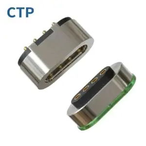
A magnetic pogo pin connector field failure should be investigated as a complete interface problem. Engineers should preserve the failed sample, document the operating conditions, reproduce the symptom, separate electrical and mechanical causes, identify the physical failure mechanism and verify the corrective action on representative production samples.
A field failure is not fully resolved when a connector starts working again after cleaning, reassembly or replacement. The engineering objective is to determine why the failure occurred, which design or process condition allowed it to occur and whether the corrective action prevents recurrence.
Magnetic pogo pin connector failures may originate from the spring-loaded contact, mating pad, magnet, housing, PCB solder joint, cable termination, environmental contamination or tolerance stack-up. The visible symptom is therefore not always located at the true root cause.
This guide presents a practical workflow for investigating intermittent connections, elevated resistance, abnormal heating, weak magnetic retention, corrosion, mechanical sticking and other field problems in custom magnetic pogo pin connector assemblies.
What Is a Magnetic Pogo Pin Connector Field Failure?
A field failure is a functional or performance problem that occurs after the connector has been installed in a device, used by a customer or exposed to its actual operating environment.
Common reported symptoms include:
- Charging starts and stops intermittently
- One contact carries less current than the others
- The connector becomes warmer than expected
- The device connects only when the cable is held at a particular angle
- A pogo pin does not return to its original height
- The magnetic connector does not align consistently
- The magnetic holding force becomes weaker over time
- Visible deposits, discoloration or corrosion appear on the contact surfaces
- The cable, housing or PCB connection becomes mechanically loose
- The device passes initial inspection but fails after movement, vibration or repeated use
These symptoms describe what the user observes. They do not yet identify the failure mechanism.
Symptom, Failure Mechanism and Root Cause Are Different
A complete investigation should separate three levels of information.
| Level | Meaning | Example |
|---|---|---|
| Symptom | What the customer or device reports | Charging stops when the cable moves |
| Failure mechanism | The physical or electrical process causing the symptom | Momentary contact separation at one pin |
| Root cause | The design, process or use condition that allowed the mechanism to occur | Insufficient working stroke caused by housing tolerance stack-up |
Replacing the connector may remove the symptom, but it does not prove that the root cause has been eliminated from other units.
Step 1: Preserve the Failed Sample
The failed connector should be preserved before cleaning, polishing, lubricating, disassembling or repeatedly operating it.
Uncontrolled handling can remove important evidence, including:
- Contamination on the contact surface
- Corrosion products
- Uneven wear patterns
- Loose particles inside the pogo pin barrel
- Position changes in the magnet or insert
- Cable damage near the strain relief
- Cracked solder joints
- Temporary electrical discontinuities
At minimum, record:
- Photographs of both mating halves
- Device serial number
- Connector part number and drawing revision
- Production lot or date code
- Returned quantity and affected quantity
- Customer-reported symptom
- Whether the failure is continuous or intermittent
- Any previous cleaning or repair activity
Where possible, retain an untested failed sample as a reference. Use separate samples for destructive analysis.
Step 2: Reconstruct the Field Conditions
Laboratory testing is only useful when it represents the conditions under which the problem occurred.
Collect information in the following categories:
| Category | Questions to Ask |
|---|---|
| Electrical Load | What voltage, current, duty cycle and operating sequence were present? |
| Mating Behavior | Was the connector mated axially, at an angle or while current was flowing? |
| Usage Frequency | How many times per day was the connector connected and disconnected? |
| Mechanical Loading | Was the cable pulled, twisted, dropped or used as a device handle? |
| Environment | Was the device exposed to humidity, sweat, dust, salt, oil or cleaning chemicals? |
| Temperature | Was the connector operated near a heat source or under changing temperature? |
| Installation | Were the housing, PCB, cable and mating pad assembled according to the approved drawing? |
| Failure Timing | Did the failure occur immediately, gradually or after a specific event? |
“Failed in normal use” is not sufficient information. Normal use should be converted into measurable electrical, mechanical and environmental conditions.
Step 3: Compare Failed, Unused and Known-Good Samples
A failed sample should not be evaluated in isolation.
A useful comparison set may include:
- The returned failed connector
- An unused connector from the same production lot
- A known-good field unit
- A retained reference sample
- A current production sample
Comparative measurements help distinguish between:
- A single damaged unit
- A production-lot variation
- A gradual field degradation mechanism
- A design-related limitation present in all units
- A change introduced by a material or process revision
Record individual results rather than reporting only an average. One abnormal contact can be hidden by the average value of a multi-pin connector.
Step 4: Reproduce the Failure Without Destroying Evidence
Begin with non-destructive evaluation.
A recommended order is:
- Visual inspection at low magnification
- Dimensional and position inspection
- Electrical continuity check
- Low-resistance measurement
- Working-height and compression verification
- Spring-return observation
- Magnetic holding and breakaway-force measurement
- Cable movement and strain-relief evaluation
- Controlled reproduction of the reported symptom
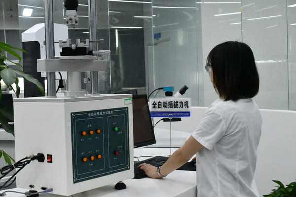
Do not begin by forcing the connector through a large number of mating cycles. Repeated operation may change the wear surface, dislodge contamination or temporarily restore contact.
Step 5: Divide the Investigation into Failure Categories
Magnetic pogo pin connector failures can normally be organized into five main categories.
Electrical Failure
- High or unstable contact resistance
- Intermittent open circuit
- Excessive voltage drop
- Abnormal temperature rise
- Short circuit between adjacent contacts
- Signal degradation or communication errors
Mechanical Failure
- Sticking or non-returning plunger
- Bent or damaged contact
- Insufficient or excessive compression
- Housing deformation
- Uneven mating-pad wear
- Loose insert or damaged mechanical stop
Magnetic Failure
- Reduced holding force
- Incorrect magnet polarity
- Magnet displacement
- Excessive assembled air gap
- Unstable final alignment
- Unintended offset or reversed mating
Environmental Failure
- Corrosion
- Condensation
- Dust or particle contamination
- Sweat or chemical residue
- Coating degradation
- Seal or adhesive failure
Assembly and Integration Failure
- Cracked PCB solder joint
- Incorrect PCB pad finish
- Loose cable termination
- Inadequate strain relief
- Housing tolerance stack-up
- Incorrect connector installation height
This classification prevents the investigation from focusing only on the pogo pin when the actual problem may be elsewhere in the assembly.
Electrical Failure Analysis
Contact Resistance
Measure resistance across the complete mated interface, not only across the discrete pogo pin.
The measurement points should be documented because the result may include:
- Pogo pin internal resistance
- Contact interface resistance
- Mating-pad resistance
- PCB trace or solder-joint resistance
- Wire and termination resistance
For low-resistance measurements, a four-wire Kelvin method is generally preferred where the product geometry allows it. IEC 60512-2-2 provides a specified-test-current method for measuring resistance across mated contacts.
Compare:
- Initial resistance
- Resistance while the connector is moved
- Resistance under nominal compression
- Resistance under minimum and maximum assembly tolerance
- Resistance before and after cleaning, when cleaning is part of the investigation
Intermittent Discontinuity
A handheld meter may not capture a short interruption. Intermittent failures may require continuous monitoring at an appropriate sampling rate while reproducing:
- Cable movement
- Housing deflection
- Connector rotation
- Vibration
- Temperature change
- Current loading
The monitoring method should record the affected channel, interruption duration and mechanical condition present when the event occurred.
Voltage Drop and Temperature Rise
Abnormal heating can originate from one contact or from another element in the current path.
Measure voltage drop across separate sections where possible:
- Pogo pin interface
- PCB connection
- Cable termination
- External connector
Temperature should be measured after the assembly reaches a stable operating condition under the specified current and duty cycle.
A low-current continuity test does not demonstrate acceptable performance at the device’s maximum operating load.
Mechanical Failure Analysis
Working Stroke and Tolerance Stack-Up
Many intermittent failures are caused by incorrect compression rather than by a defective spring.
Compare the actual assembly with the approved drawing:
- Pogo pin free height
- Installed height
- Mating-pad position
- Housing flatness
- PCB position
- Nominal working stroke
- Minimum and maximum compression
- Available over-travel
Insufficient compression can reduce contact force. Excessive compression can increase mechanical stress, accelerate wear or cause the plunger to reach its mechanical limit.
Wear Pattern Analysis
The position and shape of contact wear can provide important evidence.
| Observed Wear Pattern | Possible Interpretation |
|---|---|
| Centered circular mark | Primarily axial compression |
| Wear concentrated on one side | Angular mating or lateral misalignment |
| Long sliding track | Relative movement during mating or use |
| Uneven wear across pins | Housing flatness or tolerance-stack problem |
| Dark deposits | Possible contamination, corrosion products or damaged surface finish |
| Deep indentation | Excessive load, hard stop or concentrated contact stress |
The wear pattern should be compared with the device’s mating direction and magnet arrangement.
Plunger Sticking
A non-returning pogo pin may be associated with:
- Particles inside the barrel
- Side loading
- Barrel deformation
- Spring damage
- Contaminant migration
- Excessive working stroke
- Surface damage on the plunger
Before sectioning the sample, document free height, return movement and force behavior.
Magnetic Structure Failure Analysis
Magnetic attraction does not automatically supports correct pogo pin compression or final alignment.
Measure magnetic behavior separately from spring-loaded contact behavior.
Magnetic Holding Force
Define the pull direction during measurement. Axial pull, cable peel and lateral sliding can produce different results.
Record:
- Test direction
- Loading speed
- Assembled air gap
- Connector orientation
- Maximum force
- Force-displacement behavior
Magnet Position and Air Gap
Reduced holding force may be caused by:
- Magnet displacement inside the housing
- Incorrect magnet orientation
- Additional gap caused by adhesive or housing deformation
- Foreign material on the mating face
- Dimensional variation in the insert
- Damage to the magnet or its protective coating
Capture and Final Alignment
Evaluate both initial capture and final position.
A connector can attract from a useful distance but still stop at an offset position that produces uneven pin compression. Check:
- Lateral offset after engagement
- Angular alignment
- Contact sequence
- Compression of each pin
- Potential for reversed or shifted connection
Environmental Failure Analysis
Corrosion and Surface Deposits
Visible corrosion should not automatically be attributed to inadequate gold plating.
Potential contributors include:
- Pores or discontinuities in the surface finish
- Damage caused by sliding wear
- Contamination introduced during assembly
- Residue from cleaning agents
- Condensation inside the enclosure
- Galvanic interaction with adjacent materials
- Exposure to sweat, salt or industrial chemicals
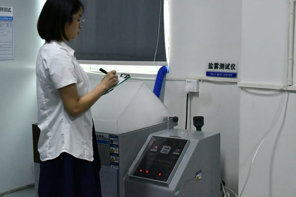
IEC 60068-2-11 provides a salt-mist test method for evaluating corrosion resistance and the comparative quality of protective coatings. A salt-mist result should not be treated as a universal prediction of service life in every field environment.
Humidity and Condensation
Humidity exposure and condensation should be distinguished.
IEC 60068-2-30:2025 addresses cyclic damp-heat conditions that generally produce condensation on the specimen. The project should still define:
- Whether the connector is powered
- Whether it is mated or unmated
- Number of cycles
- Recovery period
- Pre-test and post-test measurements
Temperature Change
Temperature change can affect:
- Housing dimensions
- Contact compression
- Adhesive retention
- Seal performance
- Magnet position
- Electrical resistance
IEC 60068-2-14 provides methods for analysing the effects of specified ambient-temperature changes. The actual temperature limits and transition conditions should reflect the device requirement.
Vibration and Shock Investigation
Vibration or impact may expose a marginal interface that appears stable during static inspection.
Possible failure mechanisms include:
- Momentary separation of contacts
- Relative movement between the pogo pin and mating pad
- Fretting-related surface damage
- Loose magnet or insert
- Cable movement transferring load to the connector
- Cracked PCB solder joints
- Housing resonance or deformation
IEC 60512-6-4 provides a sinusoidal-vibration test method for connectors, while IEC 60068-2-27 provides procedures for specified shock severities.
The test fixture should reproduce the mounting method used in the device. Testing an unsupported loose connector may produce a different result from testing the complete device assembly.
Accelerated Testing Cannot Predict Field Life with Absolute Certainty
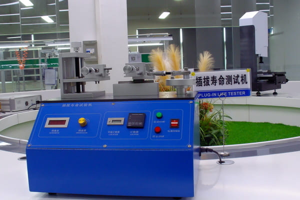
Accelerated tests can help reproduce a suspected mechanism more quickly, but they are useful only when the acceleration condition does not introduce a different failure mode.
Examples of inappropriate acceleration include:
- Increasing temperature beyond the material’s intended operating range
- Using unrealistic cycle speed that prevents normal thermal stabilization
- Applying excessive compression not present in the device
- Using salt mist to represent every type of field contamination
- Increasing current until a thermal failure unrelated to the original complaint occurs
The investigation should explain why the selected accelerated condition represents the suspected field mechanism.
Common Field Symptoms and Likely Investigation Paths
| Field Symptom | Initial Measurements | Possible Areas to Investigate |
|---|---|---|
| Charging stops when cable moves | Dynamic continuity, cable pull and working stroke | Strain relief, solder joint, compression or angular mating |
| Connector becomes hot | Voltage drop, contact resistance and thermal imaging | Contact surface, current path, termination or insufficient force |
| One pin has high resistance | Individual-channel resistance and surface inspection | Contamination, wear, damaged plating or spring-force variation |
| Pin remains compressed | Free height, return movement and internal inspection | Particles, side load, barrel deformation or spring damage |
| Magnetic force is weak | Pull-force curve, air gap and magnet position | Magnet displacement, orientation, coating or housing variation |
| Corrosion appears after use | Microscopy, residue analysis and environment review | Condensation, sweat, chemical exposure, wear or coating defects |
| Failure occurs only after vibration | Dynamic resistance and assembly inspection | Marginal stroke, loose insert, cable load or solder-joint damage |
| Connector sometimes mates offset | Capture path, final alignment and pin compression | Magnet geometry, housing guides, polarity or tolerance stack-up |
How to Confirm the Root Cause
A suspected cause should be supported by evidence from several directions.
A strong root-cause conclusion normally includes:
- The failed sample contains the suspected physical or electrical condition
- The condition explains the reported symptom
- Known-good samples do not show the same abnormality
- The condition can be reproduced under representative test conditions
- Removing or correcting the condition prevents the symptom
For example, “contamination caused high resistance” is incomplete unless the investigation identifies:
- What the contamination was
- How it reached the contact
- Why the product design or process allowed it
- How the proposed change prevents recurrence
Corrective Action Should Address the Cause, Not Only the Symptom
Possible corrective actions may involve:
- Changing the nominal working stroke
- Reducing housing tolerance variation
- Adding a mechanical stop
- Improving mating guidance
- Changing the contact-tip geometry
- Revising the mating-pad finish or geometry
- Improving sealing or drainage
- Changing cleaning or assembly controls
- Strengthening cable strain relief
- Changing magnet retention or adhesive design
- Revising PCB support around the connector
- Adding production inspection for a newly identified CTQ
Cleaning the returned connector or replacing the cable may restore operation, but these actions should not be considered permanent corrective actions unless they eliminate the underlying cause.
Validate the Corrective Action
The corrective action should be verified using samples that represent the intended production design and process.
A verification plan should include:
- The original failure condition
- The modified design or process
- Representative sample quantity
- Pre-test measurements
- Exposure or reproduction conditions
- Post-test measurements
- Acceptance criteria
- Comparison with the original failed design
Where practical, testing should include both:
- Confirmation testing: Demonstrates that the original failure no longer occurs.
- Regression testing: Confirms that the change has not created a new problem in current capacity, magnetic force, assembly, wear or environmental performance.
What to Do When the Failure Cannot Be Reproduced
An unreproduced or “no fault found” result does not prove that the connector is acceptable.
Possible reasons include:
- The field condition was not accurately reproduced
- The failure is intermittent
- Transport or handling changed the sample
- Contamination was removed before analysis
- The device firmware or power sequence contributed to the symptom
- The failed condition exists only at a tolerance extreme
- The sample recovered after cooling, drying or resting
For intermittent cases, consider:
- Longer-duration monitoring
- Combined electrical and mechanical loading
- Testing at tolerance limits
- Temperature or humidity conditioning
- Continuous channel-by-channel data recording
- Evaluation of the complete device rather than the connector alone
Information to Send for Supplier Failure Analysis
Provide as much of the following information as possible:
- Returned failed samples
- Known-good comparison samples
- Failure photographs and videos
- Device and connector part numbers
- Drawing revision
- Production lot and manufacturing date
- Field quantity and failure quantity
- Detailed symptom description
- Electrical load and operating sequence
- Estimated mating cycles
- Operating temperature and environment
- Cleaning chemicals or contaminants
- PCB, cable and housing drawings
- Any tests already performed
- Changes introduced before the failure occurred
A returned connector without field context may allow inspection of the component, but it may not provide enough evidence to identify the device-level root cause.
Engineering Reference Standards
The following standards may provide relevant test methods. The applicable edition, severity, sample state and acceptance criteria must be confirmed for each project.
- IEC 60512-2-2: Contact resistance using a specified test current
- IEC 60512-6-4: Sinusoidal vibration testing for connectors
- IEC 60068-2-27: Shock testing
- IEC 60068-2-14: Change of temperature
- IEC 60068-2-30: Cyclic damp heat
- IEC 60068-2-11: Salt mist
- IEC 60512-9-1: Mechanical operation endurance without electrical load
Frequently Asked Questions
Does a high contact resistance reading prove that the pogo pin is defective?
No. The measured resistance may include the mating pad, solder joint, PCB trace, wire and cable termination. The complete current path should be isolated and measured section by section.
Can cleaning the connector confirm the root cause?
Cleaning can help determine whether surface contamination contributed to the failure, but it can also remove evidence. Inspect and document the sample before cleaning.
Does corrosion always mean that the gold plating is too thin?
No. Corrosion can also be associated with wear damage, pores, condensation, chemical residue, galvanic interaction or contamination introduced during assembly.
Can a magnetic connector still suffer from side loading?
Yes. Magnetic attraction can assist mating, but housing geometry, magnet position and tolerance stack-up determine whether the contacts compress axially or experience lateral movement.
Why does a connector pass continuity testing but fail in the device?
A static, low-current continuity test may not reproduce cable movement, vibration, operating current, temperature change or minimum working stroke present in the device.
Should the same corrective action be applied to all production units?
Only after the affected scope has been identified. The investigation should determine whether the cause is limited to one damaged unit, one production lot, one process condition or the underlying design.
Can accelerated testing supports that there will be no future field failures?
No. Accelerated testing can support a reliability assessment when the acceleration model represents the relevant failure mechanism, but it cannot ensure zero field failures.
Prepare a Connector Failure-Analysis Package
For an engineering review, prepare:
- The failed sample and a known-good comparison sample
- The connector and device drawings
- The electrical load and operating sequence
- The actual installed working height
- The magnetic holding and release requirements
- The environmental exposure history
- The reported symptom and occurrence rate
- Production-lot and traceability information
Review available custom magnetic connector structures, access additional connector engineering guides, or submit failure details, drawings and project requirements through the Get Quote & Samples page.
CTP can review the connector geometry, electrical path, working stroke, magnetic arrangement and available failure evidence. Final root-cause conclusions and corrective actions should be supported by representative samples, traceable measurements and project-specific verification.
CTP ENGINEERING PATHS
Choose the right path for your project
Move from application requirements to a connector pair, a data-capable cable assembly, or a charging cable configuration. Final specifications are confirmed against an approved drawing and project validation plan.
Magnetic Connectors
Connector geometry, pin layout, mechanical integration and OEM/ODM review.
Engineering overview → 02Magnetic Data Cables
Power and signal allocation, cable exit, interface selection and assembly review.
Cable engineering → 03Magnetic Charging Cables
Browse the complete cable catalog and shortlist a starting structure for customization.
View cable catalog →