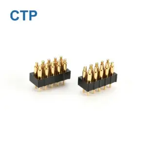
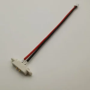
Magnetic pogo pin connector applications are most successful when the interface must mate repeatedly, tolerate limited dimensional variation or provide a shallow, detachable contact surface. The magnets assist alignment and retention, while the spring-loaded contacts transfer electrical power or signals.
The same connector architecture cannot be copied unchanged across every industry. A wearable charging interface may prioritize skin-contact exposure and compact size, while an industrial docking connector must address oil, debris, replaceable contact modules and machine alignment. An automotive interface may require controlled temperature behavior, while a UAV payload connector must balance mass, vibration and rapid module replacement.
Engineers should therefore select a magnetic pogo pin connector according to the interface function and dominant failure mode—not only according to the industry name.
Magnetic pogo pin connectors are commonly evaluated for medical charging modules, UAV payload docks, vehicle accessory interfaces, wearable charging contacts and industrial automation equipment. Their value comes from repeatable axial contact and assisted alignment, but their current, signal, sealing and durability performance must be validated for each specific product.
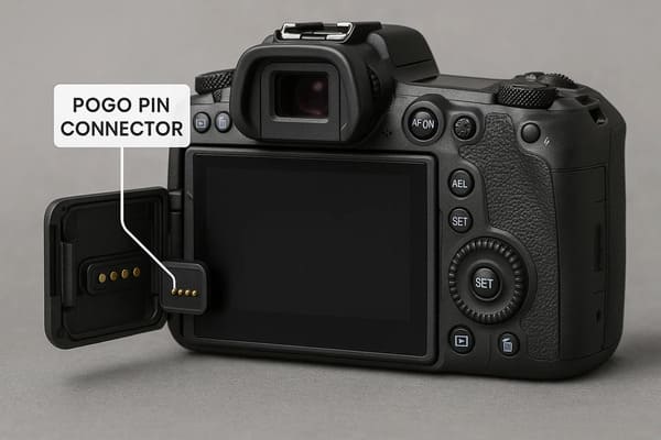
Why Engineers Use Magnetic Pogo Pin Connectors
A magnetic pogo pin connector combines three functions:
- mechanical guidance: housing features control lateral position and orientation;
- magnetic alignment and retention: magnets assist final engagement and hold the connector together;
- spring-loaded electrical contact: pogo pins compress against mating pads to carry power or signals.
This architecture may be useful when conventional deep-cavity or manually inserted connectors create problems related to access, repeated mating, enclosure depth or accidental cable pull.
Potential system-level advantages
- one-handed or blind docking;
- axial tolerance compensation;
- reduced repeated insertion into a conventional device receptacle;
- a shallow external contact surface;
- controlled magnetic separation;
- modular replacement of cables, batteries, tools or accessories;
- integration of power, detection and selected signal contacts.
Characteristics the magnetic structure does not guarantee
- a specific current rating;
- a specific mating-cycle life;
- waterproof or dustproof performance;
- high-speed data compatibility;
- vibration immunity;
- electrical isolation;
- safe hot plugging;
- compatibility with industry-standard cables.
Application Comparison at a Glance
| Industry | Typical interface | Why magnetic pogo pins are considered | Dominant design risk |
|---|---|---|---|
| Medical devices | Charging dock, removable sensor, service connection. | Shallow interface, easy cleaning and controlled cable release. | Cleaning exposure, electrical safety and product-specific regulatory requirements. |
| UAVs and field robotics | Payload module, battery dock, ground-charging interface. | Rapid module exchange and tolerance compensation. | Vibration, structural loading, weight and incomplete locking. |
| Automotive and mobility | Interior module, accessory dock, low-voltage charging or service interface. | Repeated docking and modular accessory integration. | Temperature, vibration, contact heating and standards compatibility. |
| Wearables and compact electronics | Charging cable, charging cradle, detachable accessory. | Compact interface, easy orientation and shallow enclosure opening. | Sweat, skin residue, reverse mating and exposed-contact safety. |
| Industrial automation | Robot tool, AGV dock, test fixture, replaceable sensor module. | Automated docking and replaceable contact modules. | Metal particles, machine misalignment, maintenance access and structural load. |
1. Medical Equipment and Portable Diagnostic Devices
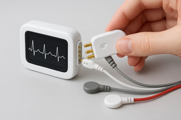
Medical equipment may use magnetic pogo pin connectors in charging cradles, portable diagnostic devices, removable sensor modules and service interfaces.
The architecture is most relevant where engineers need:
- a connector that is easy to locate with limited visibility;
- a shallow external contact surface;
- fewer deep cavities that collect residue;
- a cable that can separate under a defined pull condition;
- a replaceable charging or service module.
Suitable interface functions
A magnetic connector may be evaluated for:
- low-voltage charging;
- device-to-dock power transfer;
- removable sensor connections;
- service and programming ports;
- accessory identification;
- non-patient-circuit data or control connections.
Main engineering concerns
Cleaning and chemical exposure
Connector housings, contact finishes, adhesives and cable overmolds may be exposed to alcohol-based cleaners, detergents or other product-specific cleaning agents.
The test plan should define:
- cleaning chemical;
- concentration;
- contact time;
- wiping or immersion method;
- number of cleaning cycles;
- acceptance criteria after exposure.
Patient and user safety
A magnetic connector does not automatically satisfy medical electrical safety requirements. Engineers must review the complete device architecture, including:
- operating voltage;
- leakage and isolation requirements;
- accessible conductive contacts;
- charging-source behavior;
- fault-current protection;
- whether the interface connects to a patient-related circuit.
Breakaway behavior
Magnetic separation may reduce the load transferred by an accidental cable pull, but the connector must still remain engaged during intended use.
Test axial, side and peel separation using the final cable routing and device mass.
Medical-device validation priorities
- cleaning and disinfectant exposure;
- contact safety while disconnected;
- correct accessory identification;
- retention and breakaway force;
- resistance and temperature under load;
- mating with gloves or limited visibility;
- finished-device sealing where required;
- product-specific compliance testing.
A connector component should not be described as medical-grade, biocompatible or compliant with a medical standard unless its materials, intended contact conditions and required tests have been defined and documented.
2. UAVs, Drones and Field Robotics
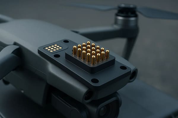
UAV and field-robotic systems frequently use removable batteries, cameras, sensors, communication modules and mission-specific payloads.
Magnetic pogo pin connectors may support rapid module exchange where the system controls alignment and uses an independent method to carry structural load.
Suitable interface functions
- removable camera or sensor payload;
- ground-based charging dock;
- swappable control or communication module;
- battery identification contacts;
- maintenance and programming connection;
- landing-station data or charging interface.
Main engineering concerns
Structural loads
Pogo pins should not carry the payload weight, flight acceleration or landing impact. The mechanical assembly should use:
- guide rails;
- locating pins;
- latches;
- screws;
- structural stops;
- a dedicated payload frame.
Magnets may assist final engagement, but a payload that must remain attached during flight normally requires an independently validated locking structure.
Vibration and intermittent contact
A static continuity check is insufficient for a UAV connector. Electrical monitoring should continue while the complete module is exposed to the relevant vibration and movement conditions.
Monitor:
- temporary opens;
- resistance fluctuation;
- communication errors;
- device resets;
- contact temperature;
- movement of the module relative to its mechanical stops.
Mass and connector density
Adding larger magnets, metal shielding and high-force contacts can increase weight. Engineers should avoid selecting each part independently at its maximum capability.
The system should balance:
- connector mass;
- contact count;
- required current;
- magnetic retention;
- mechanical lock strength;
- serviceability.
Signal architecture
A connector used for video, sensor or communication signals needs protocol-specific review. A conductive metal housing may support shielding only when the grounding, cable and PCB transitions are designed correctly.
UAV validation priorities
- module docking tolerance;
- mechanical-lock verification;
- live electrical monitoring during vibration;
- payload removal and replacement cycles;
- temperature and altitude conditions where applicable;
- contact performance after dust exposure;
- signal-channel testing with the complete cable and PCB;
- fault response after partial engagement.
3. Automotive Electronics and Mobility Systems
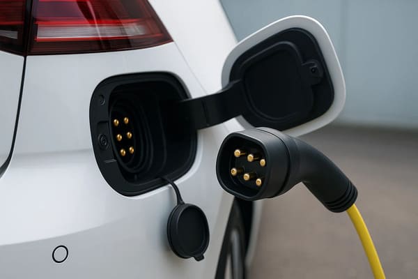
Automotive magnetic pogo pin applications should be divided into several categories instead of treating every vehicle interface as a high-current traction-charging connection.
Possible applications include:
- vehicle-interior displays and removable modules;
- seat or console accessories;
- fleet-device charging docks;
- e-bike or light-mobility charging interfaces;
- service and diagnostic connectors;
- battery-swap identification or auxiliary contacts;
- application-specific automated docking systems.
Suitable interface functions
Magnetic pogo pin connectors are easier to evaluate in controlled vehicle-module and accessory interfaces than as universal replacements for standardized public charging couplers.
Possible functions include:
- low-voltage power;
- accessory detection;
- module identification;
- charging of removable interior equipment;
- service data;
- controlled automated docking.
Main engineering concerns
Temperature and thermal cycling
Vehicle-mounted equipment can experience a wider temperature range than indoor consumer products. Temperature can affect:
- contact resistance;
- spring force;
- magnetic performance;
- housing dimensions;
- adhesive strength;
- gasket compression;
- cable flexibility.
Current and temperature rise
Current capability should be established by testing the complete conductive path:
- pogo pin;
- mating pad;
- PCB or busbar;
- wire or cable;
- solder, weld or crimp;
- switching and protection circuit.
Magnetic force does not remove oxidation, supports equal current sharing or independently prevent Joule heating.
Vibration and cable load
The connector should not be allowed to move continuously within its magnetic retention range. Repeated relative movement may change contact compression or cause surface wear.
Vehicle-mounted systems may require:
- mechanical support;
- cable strain relief;
- floating mounts;
- independent locking;
- live continuity monitoring.
Standards and compatibility
Where the project requires a standardized automotive or charging interface, a custom magnetic connector may not provide the required interoperability or certification route.
Automotive validation priorities
- temperature cycling;
- vibration with live electrical monitoring;
- continuous-current temperature rise;
- cable and termination fatigue;
- connector retention under vehicle movement;
- humidity, dust and chemical exposure;
- partial mating and hot-plug response;
- application-specific vehicle qualification.
A connector suitable for an in-cabin accessory, light-mobility device or service module should not automatically be represented as suitable for high-voltage traction-battery charging.
4. Wearables and Compact Consumer Electronics
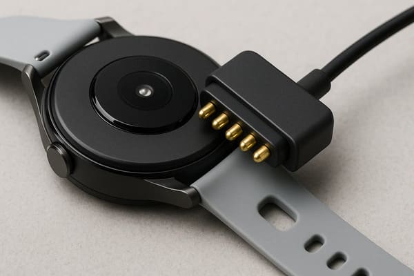
Wearables frequently have limited internal space and are charged repeatedly by end users. Magnetic pogo pin connectors can support a low-profile charging surface and help users find the correct orientation.
Typical applications include:
- smartwatches;
- fitness trackers;
- hearing or personal-audio devices;
- health-monitoring wearables;
- head-mounted electronics;
- small personal-care devices;
- charging cases and cradles.
Suitable interface functions
- charging-only connection;
- charging plus accessory detection;
- charging-cradle docking;
- low-speed service or programming contact;
- detachable sensor or strap module.
Main engineering concerns
Sweat, skin residue and cosmetics
Wearable contacts may be exposed to:
- sweat;
- skin oil;
- soap;
- lotions;
- cosmetics;
- cleaning products;
- humidity and condensation.
Materials and surface finishes should be evaluated using the actual exposure conditions rather than a generic corrosion claim.
Exposed-contact safety
A charging head with exposed source-side contacts may be bridged by jewelry, keys or other conductive objects.
Possible controls include:
- source-side power disable while unmated;
- mating detection;
- current limiting;
- short-circuit protection;
- recessed contacts;
- insulating barriers;
- cable or accessory identification.
Reverse and offset mating
Small connectors can be attached at an angle or shifted by one contact position. The pin map should be reviewed so that incorrect mating cannot connect positive power to ground or a signal contact.
Magnet proximity
Magnets should be evaluated relative to nearby sensors, speakers, storage components or other magnetically sensitive parts in the final device.
Wearable-device validation priorities
- human-use mating and separation;
- reverse and offset attachment;
- sweat and cleaning exposure;
- contact heating during charging;
- cable bending and strain relief;
- source-side short-circuit behavior;
- contact wear after repeated charging;
- finished-device sealing tests where required.
5. Industrial Automation and Robotic Equipment
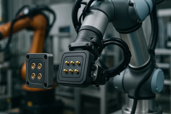
Industrial automation uses detachable interfaces in robotic tools, AGV docks, automated fixtures, movable pallets and replaceable sensor modules.
A magnetic pogo pin connector may simplify automated engagement, but the industrial environment also introduces conductive debris, machine loads and maintenance requirements that are less common in consumer products.
Suitable interface functions
- robotic tool electrical connection;
- AGV or AMR charging dock;
- production test fixture;
- automated pallet connection;
- replaceable sensor or camera module;
- machine service and programming interface.
Main engineering concerns
Mechanical docking
The machine structure should control:
- large lateral error;
- angular error;
- final mating distance;
- structural load;
- tool or pallet locking.
Magnets should assist final alignment rather than replace all mechanical guides.
Metallic debris
Permanent magnets can attract ferrous particles from machining, maintenance and factory floors.
Debris may:
- bridge adjacent contacts;
- prevent full compression;
- increase the magnetic air gap;
- scratch contact surfaces;
- create localized heating;
- cause incorrect docking detection.
Serviceability
Industrial contacts should often be designed as replaceable wear modules.
Consider:
- removable pogo pin blocks;
- screw-mounted contact cartridges;
- accessible cable connectors;
- replaceable mating-pad modules;
- maintenance alignment features;
- cycle and condition monitoring.
Controlled breakaway
Breakaway is useful only when separation is an acceptable machine response. A moving robotic tool or safety-related circuit may require positive locking rather than an easily detachable magnetic interface.
Industrial validation priorities
- robot or fixture docking repeatability;
- minimum and maximum pogo pin compression;
- live continuity during machine movement;
- dust, oil, coolant and metal-particle exposure;
- contact-module replacement time;
- cable and drag-chain fatigue;
- tool identification before power enable;
- fault response after partial mating or one failed contact.
The Same Feature Can Have Different Value Across Industries
| Connector feature | Useful effect | Possible disadvantage |
|---|---|---|
| Magnetic alignment | Simplifies final docking. | Can attract metal debris or pull misaligned contacts across pads. |
| Breakaway connection | May reduce cable-pull load on portable equipment. | May disconnect unintentionally during machine or vehicle movement. |
| Flush contact surface | May simplify enclosure cleaning and reduce cavity depth. | Exposed contacts require contamination and electrical-safety controls. |
| Spring compliance | Compensates for axial dimensional variation. | Does not compensate for unlimited lateral or angular error. |
| Multi-pin layout | Combines power, detection and signals. | Increases offset-mating and coplanarity risks. |
Cross-Industry Connector Selection Criteria
Regardless of industry, engineers should define the following before selecting or customizing a connector.
Electrical requirements
- continuous and peak current;
- operating voltage;
- acceptable voltage drop;
- maximum temperature rise;
- pin assignment;
- signal protocol and data rate;
- hot-plug and inrush behavior;
- unmated-contact electrical state.
Mechanical requirements
- available connector size;
- mating direction;
- working compression;
- allowed lateral and angular error;
- retention or breakaway force;
- cable or module load;
- mechanical locking requirements;
- expected mating frequency.
Environmental requirements
- operating and storage temperature;
- humidity and condensation;
- dust and metallic debris;
- sweat or salt exposure;
- oil, coolant or cleaning chemicals;
- water exposure;
- vibration and shock;
- maintenance and cleaning method.
Manufacturing and service requirements
- SMT, through-hole, FPC or wire termination;
- insert molding, potting or overmolding;
- connector-module replacement;
- inspection and electrical-test method;
- prototype quantity;
- production forecast;
- traceability requirements;
- field-replacement strategy.
Cross-Industry Validation Matrix
| Validation area | Recommended evaluation |
|---|---|
| Mating geometry | Straight, offset, angled, reverse and partial mating. |
| Working compression | Minimum, nominal and maximum pogo pin compression. |
| Electrical path | Continuity, resistance, voltage drop and temperature rise. |
| Dynamic operation | Live monitoring during vibration, cable movement or machine operation. |
| Retention | Axial, side, peel and torsional separation. |
| Durability | Repeated mating followed by resistance, force and surface inspection. |
| Contamination | Application-specific dust, liquids, residue and cleaning procedures. |
| Fault response | Incorrect accessory, short circuit, one open contact and unexpected separation. |
| Serviceability | Inspection access, cleaning, contact-module replacement and post-service testing. |
When Magnetic Pogo Pin Connectors Are Not the Best Choice
A conventional or standardized connector may be more appropriate when:
- the interface must remain positively locked under substantial load;
- third-party cable interoperability is required;
- a standardized charging or communication interface is mandatory;
- the connection remains permanent;
- the product cannot safely manage exposed conductive contacts;
- the environment contains uncontrolled metallic particles;
- the application cannot provide mechanical alignment;
- the available area cannot provide suitable electrical spacing;
- nearby equipment is sensitive to magnetic fields;
- the required current or signal performance exceeds the practical validated capability of the proposed structure.
Information Required for an Industry-Specific Connector Project
To evaluate a custom magnetic pogo pin connector, provide:
- industry and exact device application;
- connector location and function;
- manual or automated mating;
- pin count and pin assignment;
- continuous and peak current;
- operating voltage;
- signal or data requirements;
- available connector dimensions;
- required working compression;
- permitted lateral and angular error;
- retention or breakaway-force requirement;
- mechanical guide and locking structure;
- environmental exposure;
- cleaning and maintenance method;
- expected mating frequency;
- required validation and compliance targets;
- prototype and production quantities;
- 2D drawings, 3D models and electrical diagrams.
Frequently Asked Questions
Which industries use magnetic pogo pin connectors?
Common applications include portable medical equipment, UAV modules, vehicle accessories, wearable charging devices and industrial automation systems. Suitability depends on the exact interface rather than the industry name alone.
Do magnetic pogo pin connectors eliminate port failure?
No. They may reduce repeated insertion into a conventional receptacle and support controlled docking, but failure can still result from contamination, poor compression, cable damage, incorrect mating or inadequate electrical design.
Are magnetic pogo pin connectors waterproof?
They can be integrated into a sealed module, but the final protection level depends on the complete housing, gasket, molding, cable entry and assembled-product testing.
Can the same connector be used for medical, automotive and industrial equipment?
The same basic platform may sometimes be adapted, but materials, current, force, sealing, testing and documentation normally need to be customized for the specific application.
Can magnetic pogo pin connectors carry high current?
They can support power applications when the contact structure, number of contacts, cable, PCB, terminations and thermal design are validated together.
Can they transmit high-speed data?
Potentially, but the pin layout, return paths, PCB transitions, cable construction and shielding must be developed and tested for the required protocol.
Are magnets sufficient for robotic docking?
Magnets may assist final alignment. Robots, UAV modules and moving equipment normally also require mechanical guides, controlled stops and sometimes independent locking.
Do magnetic connectors prevent vibration-related disconnections?
Not automatically. Contact compression, housing stiffness, mechanical retention and live electrical performance must be verified under the expected vibration conditions.
Are magnetic pogo pin connectors suitable for public EV fast charging?
They should not be treated as universal replacements for standardized public charging couplers. They are more commonly evaluated in controlled, application-specific docking, accessory or battery-module interfaces.
How should an industry-specific connector be validated?
Test the complete assembled interface under the expected current, mating geometry, mechanical load, environment and maintenance conditions. Qualification should reflect the final device rather than only the individual pogo pin.
Conclusion
Magnetic pogo pin connector applications span medical devices, UAV systems, automotive electronics, wearables and industrial automation, but each industry uses the architecture for different reasons.
Medical equipment may value a shallow and cleanable docking interface. UAV systems may need rapid payload replacement. Vehicle electronics may use modular accessory contacts. Wearables often prioritize compact charging and simple user alignment, while industrial automation requires automated docking and replaceable service modules.
The engineering value comes from matching the connector to a specific interface problem. Magnets should assist alignment and retention, pogo pins should provide controlled axial electrical contact, and mechanical structures should carry alignment and structural loads.
Current, signal, sealing, durability and safety capabilities should not be inferred from the presence of magnets alone. They must be verified using the final connector, cable, PCB, enclosure and operating conditions.
CTP supports custom development of magnetic pogo pin connectors, magnetic cable assemblies, pogo pin connector assemblies and individual pogo pins.
For an industry-specific project, submit the application, pin map, current, voltage, mating method, environmental conditions and device drawings through our Get a Quote & Samples page or email bella@ytanpogo.com. The connector structure and validation plan can then be evaluated against the actual product requirements.
CTP ENGINEERING PATHS
Choose the right path for your project
Move from application requirements to a connector pair, a data-capable cable assembly, or a charging cable configuration. Final specifications are confirmed against an approved drawing and project validation plan.
Magnetic Connectors
Connector geometry, pin layout, mechanical integration and OEM/ODM review.
Engineering overview → 02Magnetic Data Cables
Power and signal allocation, cable exit, interface selection and assembly review.
Cable engineering → 03Magnetic Charging Cables
Browse the complete cable catalog and shortlist a starting structure for customization.
View cable catalog →