Engineering Summary:
Pogo pin connectors can improve test fixture repeatability and operational
efficiency by providing controlled spring-loaded contact between the test
system and the device under test (DUT). However, pogo pins do not
independently improve instrument calibration or measurement accuracy.
Their engineering value is in reducing contact-state variation through
controlled working stroke, contact force, probe-tip geometry, mechanical
fixture alignment and repeatable electrical paths. For sensitive
measurements, fixture resistance, contact resistance and signal-path
architecture must still be included in the measurement-error analysis.
Pogo pin connectors can improve test fixture repeatability and operational
efficiency by providing controlled spring-loaded contact between the test
system and the device under test (DUT). However, pogo pins do not
independently improve instrument calibration or measurement accuracy.
Their engineering value is in reducing contact-state variation through
controlled working stroke, contact force, probe-tip geometry, mechanical
fixture alignment and repeatable electrical paths. For sensitive
measurements, fixture resistance, contact resistance and signal-path
architecture must still be included in the measurement-error analysis.
How Do Pogo Pin Connectors Improve Test Equipment Performance?
Test equipment often needs to make temporary electrical connections to a
device under test without permanently soldering wires or installing a
production connector.
Spring-loaded pogo pins are useful because each contact can compress
independently against a defined target such as a PCB test pad, terminal,
battery contact or module interface.
In a properly designed test fixture, this can provide:- repeatable contact position;
- controlled contact force;
- fast engagement and release;
- replaceable test contacts;
- access to multiple electrical test points simultaneously;
- compatibility with manual or automated fixtures.
The important distinction is that the pogo pin improves the
electrical interface between the instrument and the DUT.
It does not improve the intrinsic accuracy specification of the
measurement instrument itself.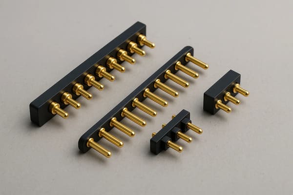
connections between test instrumentation and DUT contact points.
Accuracy and Repeatability Are Not the Same Thing
When discussing test equipment, engineers should separate measurement
accuracy from contact repeatability.| Term | Engineering Meaning |
|---|---|
| Instrument Accuracy | How closely the measurement instrument represents the actual quantity being measured |
| Measurement Repeatability | How consistently the test system produces the same result under repeated conditions |
| Contact Repeatability | How consistently the pogo pin establishes the intended electrical interface with the DUT |
| Fixture Error | Error introduced by wiring, contacts, leakage, geometry or other parts of the test fixture |
A pogo pin connector can help reduce variation in the contact interface,
but the complete measurement uncertainty still depends on the instrument,
fixture, wiring, DUT and measurement method.
Why Contact Resistance Matters in a Test Fixture
Every temporary contact introduces some electrical resistance.

For many digital or higher-impedance measurements, a small and stable
contact resistance may have limited influence.

For low-resistance, high-current or precision voltage-drop measurements,
fixture and contact resistance can become much more significant.
A simplified two-wire measurement path can be represented as:
    Instrument Lead
    →
    Fixture Wiring
    →
    Pogo Pin
    →
    DUT Contact
    →
    DUT
    →
    Return Contact
    →
    Fixture Wiring
    →
    Instrument
The measured resistance may approximately include:
    Rmeasured =
    Rlead +
    Rfixture +
    Rcontact1 +
    RDUT +
    Rcontact2 +
    Rreturn


Therefore, simply selecting a pogo pin described as “low resistance” does
not automatically supports accurate low-resistance measurements.
Stable Contact Resistance Can Matter More Than the Lowest Initial Value
In repetitive production testing, variation in contact resistance can
cause the same DUT to produce different test results across multiple
fixture cycles.
Contact resistance can change because of:
- working-stroke variation;
- different contact force;
- probe-tip contamination;
- DUT pad contamination;
- target oxidation;
- probe wear;
- fixture misalignment;
- PCB or DUT dimensional variation.
For test engineering, the target should therefore be a sufficiently low
and repeatable contact condition rather than chasing one minimum resistance
number without defining the test condition.
Use Four-Wire Kelvin Measurement When Contact Resistance Matters
When very low resistance must be measured, a conventional two-wire
architecture can include voltage drop from the test leads and temporary
contacts.

A four-wire Kelvin measurement separates the current-carrying path from the
voltage-sensing path.| Connection | Function |
|---|---|
| Force+ | Applies test current to the DUT |
| Force− | Provides the current return path |
| Sense+ | Measures voltage close to the DUT test point |
| Sense− | Provides the corresponding voltage reference |
Because the sense path carries very little current, voltage drop in the
sense contacts and wiring contributes much less to the measured voltage.

The exact fixture architecture still needs to place the Kelvin sense points
close enough to the desired DUT measurement location.
One DUT Node May Need More Than One Pogo Pin
In a Kelvin fixture, one electrical DUT node can require separate force and
sense contacts.

This is different from placing multiple pogo pins in parallel only to carry
more current.
For example:
| Test Requirement | Possible Contact Architecture |
|---|---|
| Simple Continuity | One contact per electrical node may be sufficient |
| Low-Resistance Measurement | Separate force and sense contacts may be required |
| High-Current Test | Multiple current contacts plus dedicated sense contacts may be required |
| High-Speed Signal Test | Signal contacts plus deliberate reference / return paths |
Working Stroke Controls the Contact State
A pogo pin should not merely touch the DUT.

It should normally be compressed into its approved working-stroke range
after the DUT is fully positioned inside the fixture.
A simplified relationship is:
S = Hfree - Hworkingwhere:
- S is actual compression;
- Hfree is pogo pin free height;
- Hworking is the installed height during testing.
| Condition | Possible Test Effect |
|---|---|
| Insufficient Compression | Intermittent contact or unstable resistance |
| Approved Working Stroke | Intended contact force and repeatable electrical state |
| Excessive Compression | Probe wear, DUT pad damage or spring bottoming |
| Unequal Compression | Different contact conditions across the fixture |
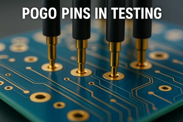
spring-loaded contact operates inside its intended compression range.
Total Travel Is Not the Recommended Test Position
Total mechanical travel describes how far the pogo pin can physically move.

Recommended working stroke describes the compression range intended for
normal electrical operation.

Test fixtures should therefore not use the mechanical bottom of the pogo
pin as the DUT positioning stop.
The Fixture Should Position the DUT — Not the Pogo Pins
The DUT should reach a repeatable mechanical datum before the pogo pins are
relied upon for the final electrical interface.
A preferred load path is:
    DUT
    →
    Fixture Datum / Nest
    →
    Mechanical Stop
    →
    Fixture Structure
rather than:
    DUT
    →
    Pogo Pin Tips
    →
    Springs
    →
    Probe Plate


If the pogo pins are used as structural stops, product dimensional
variation can directly change spring compression and measurement
repeatability.
Pogo Pins Do Not Automatically Self-Align
A standard spring-loaded pogo pin primarily accommodates movement along its
plunger axis.

It should not be expected to correct large X-Y positioning errors between
the fixture and DUT.
Repeatable fixture alignment can use:
- locating pins;
- datum surfaces;
- fixture nests;
- guide rails;
- vacuum hold-down;
- controlled clamps;
- vision alignment where required.
The mechanical fixture should place the DUT correctly before the contact
array reaches its intended working stroke.
Probe Tip Geometry Should Match the DUT Target
One pogo pin tip geometry is not ideal for every test point.| Tip Style | Possible Use | Engineering Consideration |
|---|---|---|
| Flat | Flat clean pads or terminals | Large contact area but may be sensitive to surface films |
| Rounded | General-purpose pads and repeated contact | Lower risk of aggressive scratching |
| Pointed | Targets where limited penetration of surface films is useful | Higher local pressure and greater risk of pad marking |
| Crown / Serrated | Terminals or surfaces where multiple local contact points are useful | Can increase surface marking and wear |
| Cup / Concave | Leads, pins or rounded terminals | Requires suitable target geometry |
Tip selection should consider target material, finish, contamination,
allowed pad damage, current and required cycle life.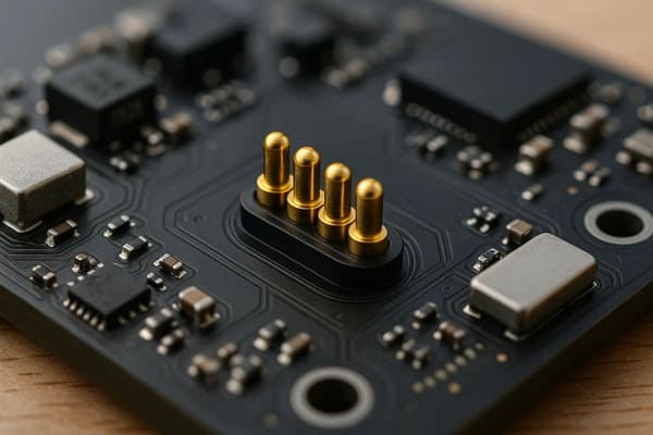
selected around the actual DUT test target.
More Contact Force Is Not Automatically Better
Increasing spring force can improve contact pressure in some conditions,
but excessive force may create other problems.
These can include:
- DUT pad indentation;
- PCB bending;
- fixture deflection;
- higher actuator force;
- increased probe wear;
- damage to small test targets.
Contact force should therefore be specified at the intended working stroke
and evaluated together with target geometry and fixture stiffness.
Multi-Pin Fixtures Create a Total Reaction Force
A single pogo pin may apply a relatively small spring force, but a fixture
can contain dozens or hundreds of spring contacts.

The total load on the DUT and fixture is approximately the sum of the
individual contact forces.

Fixture designers should therefore review:- total probe reaction force;
- DUT support locations;
- PCB bending;
- fixture-plate stiffness;
- clamp or actuator capacity;
- contact-force tolerance across the array.
Fixture Deflection Can Create Hidden Contact Variation
When a large pogo pin array is compressed, the fixture plate, DUT PCB or
mechanical nest can deflect.

If the center of a probe plate moves differently from its edges, the
contacts may no longer operate at the same working stroke.

This can create a pattern where some channels pass consistently while
others show intermittent or higher-resistance behavior.

Fixture stiffness is therefore part of the electrical contact design.
False Failures Can Originate in the Fixture
A failed production test does not always mean the DUT itself is defective.

A false fail can originate from:- contaminated pogo pin tips;
- worn probes;
- insufficient compression;
- DUT misalignment;
- fixture wiring damage;
- loose probe receptacles;
- leakage between adjacent test nodes;
- temperature-dependent fixture behavior.
Separating DUT failures from fixture failures is important because repeated
false fails increase retesting and can reduce production throughput.
Design a Fixture Self-Test Strategy
Production test systems should provide a way to determine whether the
fixture itself is still operating correctly.
Depending on the system, useful checks can include:
- known-good reference DUT;
- fixture continuity check;
- shorting or reference plate;
- contact-resistance trend monitoring;
- channel-to-channel comparison;
- probe cycle count;
- visual inspection intervals.
A fixture self-check makes it easier to distinguish between a real DUT
failure and a degraded test interface.
Contact Settling Time Can Affect Test Cycle Time
Test throughput is not determined only by how quickly pogo pins physically
touch the DUT.
A simplified production test cycle can include:
    Load DUT
    →
    Locate DUT
    →
    Clamp / Contact
    →
    Electrical Settling
    →
    Measurement
    →
    Decision
    →
    Release
    →
    Unload DUT


If poor contact requires repeated fixture closure, cleaning or retesting,
the additional time can be much larger than the original connection time.
Efficiency Should Be Measured by First-Pass Test Success
A fast fixture is not necessarily an efficient fixture if it produces
repeated false failures.
Useful production indicators can include:
- first-pass test rate;
- retest rate;
- fixture-related failure rate;
- average contact / setup time;
- probe replacement frequency;
- fixture-cleaning frequency;
- average test-cycle time.
These metrics help separate actual test-process efficiency from simple
mechanical mating speed.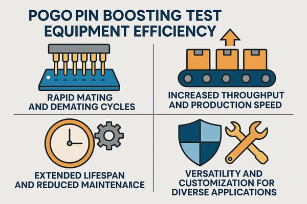
throughput also depends on loading, positioning, settling, measurement,
retesting and maintenance.
High-Current Testing Needs a Separate Power Path Review
When test probes carry significant current, resistance at the pogo pin and
DUT interface can generate voltage drop and heat.
The complete path may include:
    Test Power Supply
    →
    Fixture Cable / Busbar
    →
    Pogo Pin
    →
    DUT Pad
    →
    DUT
    →
    Return Probe
    →
    Fixture


Current capability should therefore be validated using the actual fixture
conductor size, working stroke, target surface, duty cycle and temperature.

Where several pogo pins are connected in parallel, branch current should
not automatically be assumed to divide equally.
High-Voltage Testing Requires Spacing and Leakage Control
For higher-voltage test systems, pogo pin selection is not only about
current and contact force.
The fixture may also need to consider:
- contact spacing;
- clearance;
- creepage along insulating surfaces;
- fixture contamination;
- humidity;
- insulation material;
- guarding or shielding where required;
- accessible energized contacts.
Voltage capability should therefore be evaluated from the complete test
fixture architecture rather than a pogo pin alone.
High-Speed Digital Testing Requires Signal-Integrity Design
A pogo pin can form part of a high-speed electrical path, but a generic
spring-loaded contact should not automatically be described as suitable for
any data rate.
High-speed fixture performance can depend on:
- signal-to-ground arrangement;
- return-path continuity;
- contact pitch;
- probe length;
- fixture PCB transitions;
- crosstalk;
- connector geometry;
- complete channel length.
For RF or very high-speed channels, a dedicated coaxial or controlled
impedance probe architecture may be more appropriate than a conventional
multi-pin pogo array.
Test Pin Count Does Not Define Signal Capability
Having more pogo pins gives the fixture more electrical paths, but it does
not automatically increase bandwidth or measurement quality.

The Pin Map should be developed from the actual test functions.
Possible test contacts include:
- power force;
- power return;
- Kelvin sense;
- analog measurement;
- digital input / output;
- ground / reference;
- programming;
- debug;
- fixture identification;
- shield / guard where deliberately designed.
Probe Maintenance Is Part of Measurement Control
Production pogo pins are consumable fixture components in many
high-cycle test systems.

Their electrical condition can change with use.
A maintenance plan may include:
- visual tip inspection;
- cleaning method;
- working-stroke verification;
- contact-resistance checks;
- cycle tracking;
- probe replacement criteria;
- DUT target inspection.
Replacement should ideally be based on defined fixture performance limits
rather than one generic cycle-life number.
Cycle Life Must Include Test Conditions
A statement such as “a model-specific cycle-life target validated under defined test conditions” or “one million cycles” has limited
engineering meaning unless the test conditions are known.
A useful endurance specification should identify:
- pogo pin revision;
- tip geometry;
- mating target;
- working stroke;
- contact force;
- cycling speed;
- electrical load;
- environment;
- cleaning procedure;
- failure criteria.
The same probe can achieve different service life in different fixtures.Common Test Equipment Applications
| Test Application | Possible Pogo Pin Role | Primary Engineering Focus |
|---|---|---|
| ICT Fixture | Contact PCB test points | Pin density, alignment and repeatability |
| Functional Test | Power, signals and interface simulation | Pin Map and fixture electrical path |
| Programming Fixture | Temporary debug or programming contacts | Contact stability and fast loading |
| Battery Test | Power force and voltage sense contacts | Kelvin measurement and current path |
| Connector / Module Test | Temporary interface to production terminals | Target geometry and mechanical support |
| End-of-Line Test | Power, diagnostics and functional verification | Throughput, false-fail control and maintenance |
These are fixture examples rather than universal pogo pin configurations.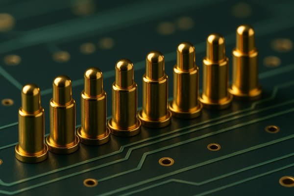
points when the fixture controls alignment and working stroke.
How to Select Pogo Pins for Test Equipment
| Parameter | Engineering Question |
|---|---|
| Test Function | Continuity, power, analog, digital, Kelvin, programming or other test? |
| Target Type | PCB pad, terminal, battery contact, connector pin or other surface? |
| Tip Geometry | Which tip provides repeatable contact without unacceptable DUT damage? |
| Working Stroke | What minimum, nominal and maximum compression will occur? |
| Contact Force | What force is required at the selected working stroke? |
| Pin Pitch | What spacing is required by the DUT test points? |
| Current | What continuous and peak test current is required? |
| Voltage | What insulation spacing and fixture architecture are required? |
| Measurement Method | Two-wire or four-wire Kelvin measurement? |
| Signal Requirement | Low-speed control or high-speed / RF channel? |
| Fixture Cycles | What cycle target and replacement criteria are required? |
| DUT Tolerance | How much dimensional variation must the fixture accommodate? |
| Maintenance | How will probes be cleaned, inspected and replaced? |
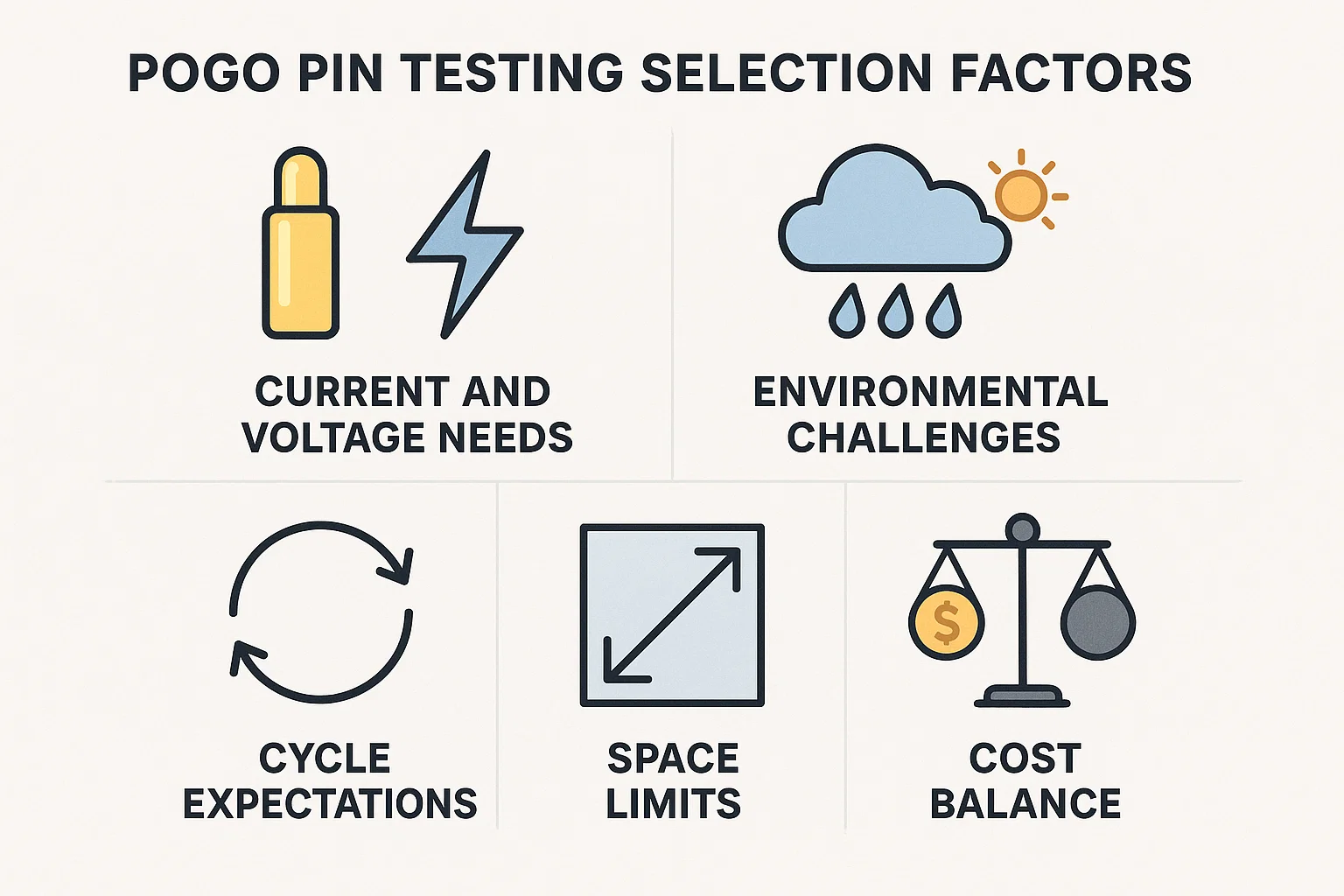
working stroke, contact force, electrical conditions and expected
fixture cycles.
Recommended Test Fixture Validation Plan
| Validation Area | Recommended Evaluation |
|---|---|
| DUT Alignment | Verify minimum, nominal and maximum positioning conditions |
| Working Stroke | Measure compression across the complete probe array |
| Contact Force | Confirm at the intended working position |
| Contact Resistance | Measure under defined target and compression conditions |
| Fixture Resistance | Characterize the complete electrical path where relevant |
| Kelvin Accuracy | Verify force and sense contact placement for low-resistance measurements |
| Fixture Deflection | Evaluate DUT and probe-plate movement under total contact force |
| Repeatability | Repeatedly load the same DUT and compare measurement distribution |
| False-Fail Evaluation | Separate fixture-related failures from actual DUT failures |
| Contamination | Evaluate representative DUT and probe-surface conditions |
| Probe Wear | Monitor tip condition and electrical behavior across defined cycles |
| Maintenance Recovery | Verify cleaning and probe-replacement procedures |
Information Required for a Test Fixture Pogo Pin Review
| Project Input | Information to Provide |
|---|---|
| DUT Type | PCB, battery, module, connector, finished product or another device |
| Test Points | Position, diameter, pitch, material and surface finish |
| Pin Map | Function of every test contact |
| Measurement Type | Continuity, resistance, voltage, current, analog, digital or other measurement |
| Electrical Conditions | Voltage, continuous current and peak current |
| Measurement Accuracy | Required instrument / system uncertainty and pass-fail limits |
| Working Stroke | Expected minimum, nominal and maximum compression |
| Fixture Tolerance | DUT and fixture dimensional variation |
| Test Cycle | Expected tests per day and required cycle life |
| Environment | Temperature, dust, oils or other contamination |
| Automation | Manual, pneumatic, robotic or another loading method |
| Project Files | DUT drawing, PCB Gerber, test-point map, fixture drawing or schematic |
Frequently Asked Questions
How do pogo pin connectors improve test equipment accuracy?
Pogo pins do not improve the calibration accuracy of the measurement
instrument itself. They can improve test-system repeatability by providing
a controlled and repeatable temporary electrical connection to the DUT.
Can contact resistance cause false test failures?
Yes. Unstable or excessive fixture contact resistance can change measured
voltage, resistance or current conditions and may cause a good DUT to fail a
test limit. The importance depends on the measurement architecture.
Why use Kelvin connections with pogo pins?
Four-wire Kelvin measurement separates force and sense paths so that much
of the voltage drop in current-carrying fixture contacts and wiring is not
included in the sensed DUT voltage. This is useful for low-resistance
measurements.
Do pogo pins automatically self-align with PCB pads?
No. The test fixture should mechanically locate the DUT. Pogo pins mainly
provide compliant movement along their spring axis and should not correct
large positioning errors.
What pogo pin working stroke should a test fixture use?
Use the approved working-stroke range for the selected pogo pin and verify
minimum, nominal and maximum fixture compression. Total mechanical travel
should not automatically be used as the normal test position.
Is more pogo pin contact force better for testing?
Not necessarily. Additional force can improve contact in some conditions,
but excessive force can damage DUT pads, bend PCBs, increase fixture
deflection and accelerate probe wear.
Which pogo pin tip is best for PCB testing?
There is no universal best tip. The choice depends on target geometry,
surface finish, contamination, permitted surface marking, electrical load
and required cycle life.
Can standard pogo pins be used for high-speed signals?
They can form part of some high-speed interfaces, but bandwidth cannot be
determined from the pogo pin alone. Return paths, contact geometry, fixture
PCB transitions and the complete signal channel must be evaluated.
How do pogo pins improve test throughput?
Spring-loaded contacts can support rapid repetitive DUT connection and
automation. The largest efficiency benefit often comes from repeatable
first-pass contact that reduces manual adjustment, cleaning and retesting,
rather than mating speed alone.
When should test pogo pins be replaced?
Replacement criteria should be based on defined conditions such as contact
resistance, tip wear, spring movement, failed fixture self-tests or
validated cycle limits rather than one universal cycle number.
Request a Pogo Pin Test Fixture Engineering Review
Explore

    pogo pin and spring-contact solutions

for PCB testing, functional test fixtures, programming fixtures and
temporary electrical interfaces.

Submit the DUT drawing, test-point layout, Pin Map, current and voltage
requirements, measurement method, expected working stroke and test-cycle
requirement through the

    Get Quote & Samples page
.


    CTP can review pogo pin tip geometry, contact layout, working stroke,
    contact force, DUT target geometry and PCB or fixture integration for
    custom test equipment. Final measurement repeatability, electrical
    performance, fixture life and test throughput depend on the complete
    instrumentation, fixture, DUT and project-specific validation.