Engineering Summary:
A magnetic pogo pin connector does not make an industrial tablet or charging dock intrinsically safe, flameproof or explosion-protected by itself. Hazardous-area suitability depends on the complete tablet, dock, power supply, charging circuit, enclosure, exposed contacts, temperature limits and certification scope. Magnetic capture and spring-loaded contacts can improve docking ergonomics, but power should only be enabled through a validated system state.
A magnetic pogo pin connector does not make an industrial tablet or charging dock intrinsically safe, flameproof or explosion-protected by itself. Hazardous-area suitability depends on the complete tablet, dock, power supply, charging circuit, enclosure, exposed contacts, temperature limits and certification scope. Magnetic capture and spring-loaded contacts can improve docking ergonomics, but power should only be enabled through a validated system state.
Industrial tablet charging docks are both electrical systems and human-machine interfaces.
Operators may need to dock a tablet while wearing gloves, working in low visibility, standing beside vibrating machinery or handling equipment contaminated by dust, oil or moisture.
A well-designed magnetic pogo pin interface can reduce the precision required from the operator. However, the magnets should assist initial positioning only. The dock structure must still control tablet alignment, support its weight, protect the contacts and establish a safe electrical state before charging begins.
This guide explains how
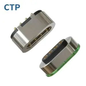
custom magnetic connectors
and
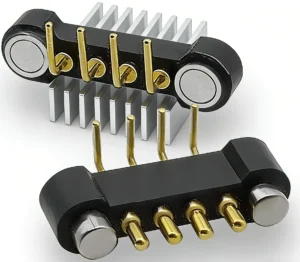
magnetic cable assemblies
may be evaluated for rugged industrial tablets and charging docks without incorrectly treating the connector as a complete explosion-protection solution.Explosion-Proof, Explosion-Protected and Intrinsically Safe Are Not Interchangeable
“Explosion-proof” is often used as a general market term, but engineering documentation should identify the actual protection concept and certification scope.| Term | Engineering Meaning | Why It Matters to a Charging Dock |
|---|---|---|
| Explosion-protected equipment | A general description for equipment evaluated for use in an explosive atmosphere | The complete tablet and dock must be evaluated according to the applicable protection concept |
| Intrinsic safety “i” | Electrical circuits are limited so that they are incapable of causing ignition under the assessed conditions | Connector energy, charging voltage, current, capacitance, inductance and fault conditions are part of the system assessment |
| Flameproof enclosure “d” | An enclosure is designed and tested to contain an internal explosion and prevent propagation to the surrounding atmosphere | This is an enclosure protection concept, not a property created by using pogo pins |
| Protection by enclosure “t” | An enclosure and surface-temperature limitation are used for combustible-dust environments | Dust ingress, accumulation and accessible surface temperature must be controlled at equipment level |
| IP rating | Classification of protection provided by an enclosure against access, dust and water | An IP rating does not independently establish explosion protection |
Engineering Note:
Do not describe a magnetic pogo pin connector as “ATEX certified,” “IECEx certified,” “intrinsically safe” or “explosion-proof” unless that exact connector or assembly is included within a valid certification scope.
Do not describe a magnetic pogo pin connector as “ATEX certified,” “IECEx certified,” “intrinsically safe” or “explosion-proof” unless that exact connector or assembly is included within a valid certification scope.
First Decide Where Charging Is Permitted
Before designing the connector, determine whether the industrial tablet may be charged inside the classified hazardous area.

The permitted charging location should be confirmed from the product certificate, equipment marking, user instructions and applicable site rules.
Architecture A: Charging Only in a Non-Hazardous Area
The tablet is removed from the classified area and placed in a conventional charging dock in a safe location.This architecture may simplify:
- Charging-power design
- Power-supply selection
- Dock cooling
- Service and maintenance
- Electrical-access restrictions
The tablet itself may still require an explosion-protection certification, but the charging dock may fall outside the hazardous-area equipment boundary if it is used only in the defined safe location.Architecture B: Charging in a Controlled Transitional Area
The dock is installed in a designated charging station, equipment room or controlled boundary area.Review:
- Area classification
- Power-supply location
- Cable and barrier routing
- Tablet entry and exit procedures
- Operator access control
- Site-specific work instructions
Architecture C: Charging Inside the Classified Area
This is the most demanding architecture. The tablet, charging dock, external power source, interface circuits and complete charging state may require evaluation as one explosion-protected system.Define:
- Gas or dust classification
- Equipment group and category or protection level
- Temperature class or maximum surface temperature
- Protection concept
- Permitted input voltage and current
- Maximum internal energy under normal and fault conditions
- Connector mating and separation states
- Certification boundary
The decision to charge inside a hazardous area should be made with the tablet manufacturer, charging-system designer and qualified Ex certification body.Define the Industrial Tablet Docking Workflow
HMI requirements should be developed from the real operator workflow rather than from the connector alone.- The operator approaches the dock while carrying the tablet.
- The tablet enters the mechanical lead-in area.
- Rails, guides or a cradle control the tablet position.
- Magnets assist the final approach.
- The pogo pins reach the intended working compression.
- The dock confirms a valid seated state.
- Charging power is enabled.
- The system displays the charging or fault status.
- Power is disabled before or during undocking.
- The mechanical retention is released and the tablet is removed.
Every step should be evaluated while the operator is wearing the gloves, protective clothing and other personal protective equipment used at the site.Magnetic Pogo Pins Should Assist Docking, Not Carry the Tablet
A rugged tablet may be significantly heavier than a small wearable device. The connector magnets and pogo pins should not normally be the only components supporting the tablet.The preferred mechanical load path is:
Tablet enclosure → dock cradle or rails → dock frame → mounting structurerather than:
Tablet weight → magnets → pogo pins → solder joints → PCBMechanical support may include:
- Bottom support shelf
- Side guide rails
- Rear support surface
- Corner locating features
- Mechanical latch
- Spring clamp
- Vehicle or wall-mount restraint
Magnets can help pull the final interface into position, but the cradle should absorb tablet weight, vibration, impact and operator-applied force.Design for Operators Wearing Gloves
Thick gloves reduce tactile feedback and make small connector features difficult to manipulate.A glove-friendly charging dock may require:
- A wide mechanical lead-in
- Large accessible release features
- One-handed docking where required
- Clear visual orientation
- Asymmetric housing geometry
- Positive seating feedback
- Status indication visible from the normal working position
- No small exposed plugs or protective caps that must be removed by hand
Convert HMI Claims into Measurable Requirements
| HMI Goal | Measurable Engineering Requirement |
|---|---|
| Easy docking | Permitted approach angle and positional offset |
| Glove-compatible operation | Minimum accessible feature size and required operating force |
| Clear seating | Defined mechanical stop, latch position or charging indication |
| Stable charging | No electrical interruption under approved vibration and tablet movement |
| Easy removal | Defined release force and release motion |
| Incorrect-docking prevention | No unsafe electrical state at credible reversed, tilted or partial positions |
| Easy cleaning | Accessible contact surfaces and validated cleaning procedure |
Do Not Energize the Interface Based Only on Magnetic Contact
Magnetic attraction does not prove that the tablet is fully seated or that every contact is correctly aligned.

The electrical design should consider a controlled power-enable sequence.
Example Docking State Machine
| State | Connector Condition | Recommended Electrical Behavior |
|---|---|---|
| Disconnected | No valid tablet detected | Power contacts disabled or energy limited according to the approved protection concept |
| Approaching | Magnets may begin attracting the tablet | No charging power enabled |
| Partial contact | One or more contacts may touch | System remains in a controlled non-charging state |
| Detection valid | Identification or seating condition is confirmed | Controller evaluates polarity, voltage and fault state |
| Fully seated | Mechanical stop and required contacts are valid | Charging may be enabled within the certified system limits |
| Fault | Short circuit, contamination, overtemperature or invalid device | Power remains disabled or is removed |
| Undocking | Detection state is lost or latch is released | Charging power is disabled before uncontrolled contact separation |
Engineering Note:
This is a design framework, not a certified intrinsic-safety circuit. The actual state machine, allowable energy and fault behavior must be reviewed as part of the complete Ex equipment assessment.
This is a design framework, not a certified intrinsic-safety circuit. The actual state machine, allowable energy and fault behavior must be reviewed as part of the complete Ex equipment assessment.
Evaluate Every Credible Mating State
The connector may pass through several electrical states while the tablet is inserted or removed.Review:
- Completely disconnected
- Tablet entering the cradle at an angle
- One side contacting before the other
- One pogo pin touching first
- Radial or lateral offset
- Incorrectly oriented tablet
- Partial magnetic retention
- Fully seated condition
- Vibration-induced movement
- Tablet removal while charging
For each state, determine:
- Which contacts can touch
- Whether any contact is energized
- Whether adjacent contacts can bridge
- Whether reverse polarity is possible
- Whether an arc or hot surface could be produced
- Whether the system detects the invalid state
- How quickly power is removed
Pin Map and Contact Sequencing
A hazardous-area dock may require more contacts than simple positive and negative charging terminals.Possible functions include:
- Positive power
- Power return
- Protective or reference ground where applicable
- Dock detection
- Tablet identification
- Temperature sensing
- Charging authorization
- Communication or diagnostics
| Contact Function | Primary Engineering Question |
|---|---|
| Power | When is it energized and what fault energy is available? |
| Return | Is the return path controlled under every mating state? |
| Detection | Does it prove full seating or only initial contact? |
| Identification | Can the dock distinguish an approved tablet or accessory? |
| Temperature sensing | Where is temperature measured and how does the charger respond? |
| Communication | Does the signal circuit remain within the approved Ex-system limits? |
Contact length, target height or housing geometry may be used to create controlled sequencing, but the sequence must be verified across dimensional tolerances and wear.Mechanical Guidance Is More Important Than Magnetic Force
Stronger magnets do not automatically improve dock reliability.Excessive magnetic force may cause:
- High impact during final seating
- Excessive pogo pin compression
- Difficult removal while wearing gloves
- High load on the tablet enclosure
- Rapid attraction of ferrous debris
- Unexpected movement of nearby steel parts
Insufficient magnetic force may cause intermittent seating or unstable contact under vibration.Separate the Magnetic Requirements
| Requirement | Definition |
|---|---|
| Capture | How the tablet responds when it enters the final docking region |
| Alignment assistance | How magnets help move the connector toward the mechanical guides |
| Retention | How the connector remains seated under vibration and operator movement |
| Release | How much force and which motion are required to remove the tablet |
In vehicle, wall-mounted or vibrating applications, a mechanical latch may be required even when magnets are used for alignment.Pogo Pin Working Stroke and Dock Tolerance
The working stroke is the compression applied to each pogo pin after the tablet reaches its final seated position.The dimensional stack may include:
- Pogo pin free-height tolerance
- Dock PCB position
- Connector housing dimensions
- Tablet contact-pad position
- Cradle guide dimensions
- Latch and stop position
- Tablet-enclosure deformation
- Dock-frame deformation
- Contamination between the tablet and dock
| Condition | Possible Risk | Required Check |
|---|---|---|
| Minimum compression | Insufficient force or intermittent charging | Electrical stability under maximum permitted gap |
| Nominal compression | Normal operating condition | Resistance, force and temperature rise |
| Maximum compression | High force, PCB loading or mechanical bottoming | Remaining travel and structural margin |
| Uneven compression | Different contact resistance or current distribution | Tablet flatness, guide alignment and pin-height variation |
The cradle and mechanical stop should control the final position. Magnetic force should not drive the pogo pins into uncontrolled full travel.Gas and Dust Environments Create Different Connector Risks
Explosive Gas or Vapour Atmospheres
Review potential ignition sources such as:
- Electrical arcs during mating or separation
- Short circuits across exposed contacts
- Hot contacts or PCB traces
- Stored electrical energy
- Component faults
- Electrostatic discharge
Combustible Dust Atmospheres
Additional concerns may include:
- Dust accumulation on horizontal dock surfaces
- Conductive dust bridging contacts
- Ferrous particles attracted by magnets
- Dust inside spring-loaded contacts
- Insulating dust layers increasing surface temperature
- Cleaning procedures that disturb combustible dust
The dock geometry should minimize recesses where dust can collect and should provide access for the approved cleaning method.Ferrous Debris Is a Specific Magnetic-Connector Risk
Magnetic docks may attract steel particles from fabrication, mining, maintenance or machining environments.Ferrous debris may:
- Prevent full seating
- Bridge adjacent contacts
- Scratch or wear contact surfaces
- Change the magnetic air gap
- Create intermittent charging
- Interfere with detection of a valid docked state
Risk reduction may include:
- Recessed magnetic components
- Contact spacing appropriate to credible debris
- Non-energized exposed contacts
- Docked-state detection
- Cleanable connector faces
- Inspection and maintenance intervals
- Protective covers when the dock is not in use
Ingress Protection and Explosion Protection Are Separate Requirements
An IP rating evaluates enclosure protection against access, dust and water. It does not by itself demonstrate that equipment is suitable for an explosive atmosphere.Potential leakage paths include:
- Pogo pin to connector housing
- Magnet to housing
- Housing to tablet enclosure
- Dock housing joints
- PCB or cable entry
- Adhesive interfaces
- Charging-dock power connection
Any IP statement should identify the complete tested tablet or dock, its connector state and the defined test condition.Charging Current and Surface Temperature
Charging performance must be evaluated across the complete current path.The path may include:
- Dock power source
- Protection or energy-limiting circuit
- Dock PCB traces
- Pogo pin termination
- Pogo pin internal contact path
- Tablet mating pad
- Tablet PCB
- Battery-charging circuit
Define:
- Operating voltage
- Continuous charging current
- Peak current
- Duty cycle
- Ambient-temperature range
- Maximum permitted voltage drop
- Maximum permitted connector temperature rise
- Equipment temperature class or maximum surface-temperature requirement
- Normal and fault conditions
“Supports 10A” is not a complete engineering requirement and should not be published unless the specific connector, conductor, protection circuit, test boundary and temperature limits are defined.Parallel Contacts
Multiple pogo pins may be connected in parallel for power or return, but current should not be assumed to divide equally.Current sharing may be affected by:
- Working-stroke variation
- Contact-resistance variation
- Unequal target-pad contact
- PCB-routing differences
- Contamination
- Solder-joint variation
Where parallel contacts carry meaningful current, evaluate channel-level voltage drop and temperature where practical.Dock Status and Operator Feedback
Operators need to distinguish between mechanically docked, electrically connected, charging and fault states.Possible feedback methods include:
- Tablet-screen indication
- Dock status light included within the approved equipment design
- Audible indication where appropriate
- Mechanical latch position
- Remote status through the HMI system
The operator should not need to infer a safe charging state only from the magnetic “click.”Service, Cleaning and Maintenance
A dock installed in a hazardous or harsh industrial environment requires a defined inspection and maintenance process.Inspect:
- Contact contamination
- Ferrous debris
- Pogo pin movement
- Tablet target-pad wear
- Housing damage
- Latch operation
- Cable and strain relief
- Fasteners and dock mounting
- Seals and protective covers
Cleaning materials and methods should be compatible with the connector finish, enclosure materials, seals and hazardous-area operating procedures.Define the Certification Boundary
The certification boundary should be agreed before the connector and dock architecture are finalized.| System Element | Certification Question |
|---|---|
| Industrial tablet | For which zones, groups, temperatures and protection concepts is it approved? |
| Dock | Is it used in a safe area, transitional area or classified area? |
| Connector | Is it a certified Ex component or included only as part of the equipment assessment? |
| Power supply | Where is it located and what limits apply to its output? |
| Associated apparatus | Are barriers or other energy-limiting devices part of the system? |
| Cable | Is its capacitance, inductance, conductor size and routing relevant to the approved system? |
| Charging state | Is charging permitted in the classified area under the equipment certificate? |
The connector supplier should provide dimensional, material, electrical and test information required by the equipment designer, but the final Ex classification belongs to the assessed equipment or system.Charging-Dock Architecture Selection Matrix
| Project Requirement | Recommended Starting Direction | Primary Review |
|---|---|---|
| Charging outside hazardous area | Conventional rugged dock with controlled pogo pin interface | Mechanical durability, contamination and charging performance |
| Charging at a controlled boundary | Fixed dock with defined operating procedure | Area classification, cable routing and user access |
| Charging inside classified area | Complete Ex-system development | Protection concept, energy limits, fault analysis and certification |
| Heavy tablet in vibrating equipment | Cradle, mechanical latch and pogo interface | Load path, vibration and contact stability |
| Frequent glove-operated docking | Wide lead-in, magnet-assisted alignment and clear status feedback | One-handed use and incorrect-docking prevention |
| Combustible-dust environment | Cleanable dock with controlled exposed-contact state | Dust accumulation, ferrous debris and surface temperature |
| Vehicle-mounted tablet | Mechanical restraint with spring-loaded electrical interface | Shock, vibration, release and cable load |
Recommended Engineering Validation
| Requirement | Recommended Evaluation |
|---|---|
| Dock fit | Tablet, cradle, guides, latch and connector dimensional inspection |
| Pin Map | Continuity, polarity, identification and short-circuit verification |
| Docking envelope | Maximum permitted approach angle and positional offset |
| Partial mating | Tilted, offset, reversed and one-contact-first states |
| Power sequencing | Disconnected, detection, charging, fault and undocking states |
| Working stroke | Minimum, nominal and maximum contact compression |
| Spring force | Individual contact and total connector reaction |
| Magnetic behavior | Capture, alignment assistance, retention and release |
| Mechanical support | Tablet weight, operator force, shock and vibration load path |
| Contact resistance | Defined channel-level measurement at the approved working stroke |
| Charging operation | Voltage drop, current sharing and temperature rise |
| Fault conditions | Short circuit, open circuit, invalid device and overtemperature response |
| Dust and debris | Representative dust, ferrous particles and contamination exposure |
| Cleaning | Approved cleaning process and repeated-cleaning evaluation |
| Mechanical operation | Project-defined docking cycles with post-test inspection |
| Ingress protection | Complete tablet or dock enclosure in the defined state |
| Ex protection | Evaluation according to the selected protection concept and certification plan |
Information Required for a Custom Industrial Tablet Dock
- Tablet model and application
- Charging location and hazardous-area classification
- Required certification market
- Selected explosion-protection concept
- Complete Pin Map
- Operating voltage
- Continuous and peak charging current
- Power-enable and fault-response logic
- Tablet dimensions and weight
- Dock orientation and mounting method
- Required approach angle and positional tolerance
- Glove and operator-use requirements
- Pogo pin working height and stroke
- Magnetic capture and release requirements
- Mechanical latch or restraint requirements
- PCB, enclosure and dock drawings
- Gas, dust, water, chemical and temperature exposure
- Expected docking frequency
- Prototype and annual production quantity
Common Design Mistakes
| Mistake | Possible Consequence | Better Approach |
|---|---|---|
| Calling the connector intrinsically safe | The system certification boundary is misrepresented | Evaluate the complete tablet, dock and charging circuit |
| Assuming magnetic contact is spark-free | Arcing may still occur during partial contact or separation | Control energy and power sequencing across all states |
| Using magnets to carry the tablet weight | Connector, PCB or housing damage | Support the tablet through the cradle and dock frame |
| Enabling power before full seating | Short circuit, arcing or unstable charging | Use validated detection and authorization logic |
| Ignoring glove use | Operators cannot dock or release the tablet reliably | Validate the complete workflow with real PPE |
| Ignoring ferrous debris | Particles may bridge contacts or prevent seating | Design cleanable surfaces and controlled exposed-contact states |
| Using an IP rating as proof of Ex safety | The actual ignition risks remain unevaluated | Treat ingress and explosion protection as separate requirements |
| Publishing a universal cycle-life value | The claim may not match the actual dock conditions | Define stroke, load, contamination and acceptance criteria |
| Ignoring tablet removal during charging | Power may remain present during uncontrolled separation | Validate undocking detection and power removal |
| Choosing the connector after Ex certification begins | Late redesign and repeated certification work | Define the charging architecture and certification boundary early |
Engineering Reference Standards
The applicable editions and certification requirements should be confirmed with the responsible certification body and target market.-
IEC 60079-0 — Explosive atmospheres: General requirements for Ex equipment and components
-
IEC 60079-11 — Equipment protection by intrinsic safety “i”
-
IEC 60079-25 — Intrinsically safe electrical systems
-
IEC 60079-1 — Equipment protection by flameproof enclosure “d”
-
IEC 60079-31 — Equipment dust ignition protection by enclosure “t”
-
Directive 2014/34/EU — Equipment and protective systems for potentially explosive atmospheres
-
IEC 60529 — Degrees of protection provided by enclosures
Frequently Asked Questions
Are magnetic pogo pins intrinsically safe?
Not by themselves. Intrinsic safety applies to an assessed electrical circuit and system. The connector, charging circuit, available energy, fault conditions and complete equipment must be evaluated together.Are magnetic pogo pin connectors spark-free?
Magnetic alignment does not ensure spark-free operation. Arcing may still occur if energized contacts mate, separate or short under certain conditions. Power sequencing and energy limitation must be designed at system level.Can an explosion-protected tablet be charged inside a hazardous area?
Only when the product certificate, charging-system design and site rules permit it. Many projects require charging in a non-hazardous area or through a specifically assessed charging system.Does IP68 mean the charging dock is explosion-proof?
No. An IP rating addresses enclosure protection against access, dust and water. Explosion protection requires a separate assessment of ignition risks and the selected protection concept.Should magnets hold the complete industrial tablet?
Normally the cradle, guide rails, backplate or latch should carry the tablet weight and operational loads. Magnets can assist final alignment and connector retention.Can operators dock the tablet while wearing gloves?
Yes, when the dock is designed with an adequate lead-in, accessible release features, clear orientation, controlled seating and visible status feedback. The workflow should be validated using the actual gloves.How can the dock prevent power during partial contact?
A project may use detection contacts, identification, controlled contact sequencing and electronic authorization before charging power is enabled. The final design must follow the applicable Ex protection concept.Can metallic dust interfere with a magnetic dock?
Yes. Ferrous particles can be attracted to magnets, interfere with seating or bridge contacts. The connector face should be cleanable and evaluated using representative contamination.How should magnetic force be selected?
Define capture, retention and release separately. The force should be evaluated together with tablet weight, vibration, pogo pin reaction, mechanical latch and glove-operated removal.What information is needed for a custom charging dock connector?
Provide the hazardous-area classification, charging location, Pin Map, voltage, current, tablet dimensions, dock structure, power-enable logic, environmental conditions and certification requirements.Prepare Your Industrial Tablet Dock Project
Review the

    custom magnetic connector range
,
compare

    custom magnetic cable assemblies
,
or access additional

    magnetic connector engineering guides
.

Submit the tablet, dock, PCB, Pin Map and certification requirements through the

    Get Quote & Samples page
.

CTP can review the contact layout, pogo pin stroke, magnetic alignment, PCB or cable termination, docking tolerance and mechanical structure. Final explosion-protection classification, charging permission and certification must be determined for the complete tablet and dock system by the responsible equipment manufacturer and certification body.