Engineering Summary:
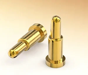
A magnetic pogo pin interface can transfer power, detection and selected signals between a robot wrist and a removable end-effector, but it should not be treated as the complete robotic tool changer. The mechanical coupling must carry the tool mass, torque, acceleration and process loads. The electrical interface should engage only after the tool is correctly located and mechanically secured, and high-energy circuits should be isolated or controlled before coupling and separation.
A magnetic pogo pin interface can transfer power, detection and selected signals between a robot wrist and a removable end-effector, but it should not be treated as the complete robotic tool changer. The mechanical coupling must carry the tool mass, torque, acceleration and process loads. The electrical interface should engage only after the tool is correctly located and mechanically secured, and high-energy circuits should be isolated or controlled before coupling and separation.
Automatic tool changing allows one industrial robot to use different grippers, inspection heads, dispensing tools, fastening units and other end-effectors during the same production process.The connector interface is only one part of this system. A complete robotic tool changer may also require a mechanical coupling, locking mechanism, tool stand, position sensing, tool identification, electrical power, communication, pneumatics, vacuum or fluid transfer.
A custom magnetic pogo pin interface may be useful when the project requires compact electrical contacts, repeated mating, tolerance compensation or an interface shaped around the tool changer. Engineers who need the general connector architecture can first review the
spring-loaded magnetic connector design guide
.A Robotic Tool Changer Has Two Different Interfaces
The mechanical coupling and the utility interface perform different functions and should be evaluated separately.| System Layer | Primary Function | Examples of Design Elements |
|---|---|---|
| Mechanical coupling | Locate, lock and support the end-effector | Robot flange, coupling plates, locking mechanism, locating features and structural fasteners |
| Electrical utility interface | Transfer power, detection, identification and selected signals | Pogo pins, mating targets, connector housing, PCB and cable termination |
| Pneumatic or fluid interface | Transfer compressed air, vacuum, cooling water or process fluids where required | Valves, self-sealing couplings, hoses and fluid modules |
| Control and safety interface | Confirm tool identity, locked state and permitted operating condition | Lock sensors, tool-presence detection, tool ID and controller logic |
The mechanical coupling should normally carry the tool weight, process force, robot acceleration and external moments. The pogo pins should provide compliant electrical contact rather than function as structural supports.

A preferred mechanical load path is:

End-effector → mechanical coupling → robot flange → robot wrist

rather than:

End-effector load → magnets → pogo pins → solder joints → PCB
Engineering Note:
Magnetic attraction may assist final electrical alignment, but the tool changer locking system should define the secured mechanical state.
Magnetic attraction may assist final electrical alignment, but the tool changer locking system should define the secured mechanical state.
Define the Complete Tool-Change Sequence
The interface should be designed around the complete robotic motion and control sequence rather than only the final mated position.| Tool-Change State | Mechanical Condition | Recommended Electrical Condition |
|---|---|---|
| Tool parked | End-effector is supported by the tool stand | High-energy circuits are disabled or controlled according to the system design |
| Robot approaching | Robot flange enters the tool-stand alignment region | No valid tool connection should be assumed |
| Initial alignment | Mechanical guides and any magnetic capture features begin locating the interface | Contacts may remain inactive or energy-limited |
| Mechanical coupling | Coupling plates reach the intended position | Tool presence may be detected, but operating power is not yet automatically authorized |
| Locked state confirmed | Locking mechanism and position sensors confirm secure coupling | Tool identity and electrical conditions may be checked |
| Utilities enabled | Tool remains mechanically secured | Power, communication, air or other utilities are enabled in the approved order |
| Operating | Tool performs its intended process | Current, communication, lock state and faults are monitored as required |
| Release requested | Robot returns the tool to the stand | Process energy and high-current circuits are disabled before uncoupling |
| Mechanical unlock | The tool stand supports the end-effector and the lock is released | Remaining signal or detection contacts separate in the defined state |
| Robot withdrawn | Robot leaves the parked tool | The tool-side exposed-contact state remains controlled |
The sequence should include failure states such as incomplete locking, incorrect tool identity, loss of air pressure, contamination, failed power removal and a tool that is not correctly seated in the stand.Magnetic Capture Should Not Replace Mechanical Tool Location
The positional repeatability required by the process should be provided primarily by the tool changer geometry, locating features and robot motion.

Magnets may assist the final approach of the electrical connector, but stronger magnetic force does not automatically improve the complete tool-change system.
Excessive magnetic attraction may:
- Increase impact during final coupling
- Create side loads on the pogo pins
- Make intentional tool release more difficult
- Attract welding particles or other ferrous debris
- Mask an incomplete mechanical coupling
- Increase load on the connector housing or PCB
Insufficient attraction may allow the electrical interface to remain offset even when the mechanical tool changer is locked.

Define magnetic capture, electrical-interface retention and tool-changer mechanical locking as separate requirements.
Choose the Utility Interface Architecture
A robotic tool changer does not need to route every utility through the same contact technology.| Architecture | Possible Use | Primary Trade-Off |
|---|---|---|
| All electrical paths through one pogo array | Low-power tools with detection and basic signals | Compact layout, but greater thermal, spacing and signal-allocation complexity |
| Separate power and signal contacts | Tools requiring meaningful power together with sensors or identification | More interface area, but clearer electrical separation |
| Dedicated high-current module plus pogo signal array | Servo tools, heaters, weld-related equipment or higher-power actuators | More components, but power contacts can be optimized independently |
| Electrical interface plus separate pneumatic modules | Grippers, clamps, vacuum tools and pneumatic actuators | Requires coordination between electrical and fluid coupling states |
| Dedicated communication connector | Tools requiring a qualified industrial communication channel | Less compact, but easier to preserve the intended communication interface |
For some tools, a pogo pin interface may be appropriate for identification, sensors and control while a separate contact module carries the main actuator or welding power.High-Current Design Begins with the Tool Load Profile
“High current” is not a complete connector specification. The project should define the entire electrical load and thermal boundary.Provide:
- Operating voltage
- Continuous current
- Peak current and duration
- Duty cycle
- Motor starting, heater or actuator inrush current
- Number of parallel power and return contacts
- Permitted voltage drop
- Permitted temperature rise
- Robot wrist and tool-side ambient temperature
- Whether current is present during coupling or separation
The complete current path may include:- Robot-side power supply
- Protection and switching circuit
- Robot-side cable
- Connector termination
- Spring-loaded contact path
- Mating target
- Tool-side cable or PCB
- End-effector load
Connector heating cannot be evaluated from the pogo pin diameter alone. Contact construction, working stroke, mating condition, conductor size, cable routing and enclosure cooling all affect the result.Do Not Assume Parallel Contacts Share Current Equally
Multiple contacts may be connected in parallel, but current distribution can vary because of:- Pogo pin compression differences
- Contact-resistance variation
- Mating-target flatness
- PCB routing resistance
- Uneven contamination or wear
- Different termination paths
Channel-level voltage drop and temperature should be evaluated where parallel contacts carry significant current.Isolate Energy Before Tool Release
Electrical contacts should not be assumed to separate safely while carrying the full tool load.

Before mechanical unlocking, the system may need to:- Stop the active process.
- Disable tool actuators or heaters.
- Remove high-current power.
- Discharge stored electrical energy.
- Move pneumatic or vacuum circuits to their defined safe condition.
- Confirm that the tool is supported by the stand.
- Confirm permission to unlock.
Detection or sequencing contacts can support this workflow, but they do not replace a controlled power-switching and safety architecture.
Engineering Note:
Do not use “arc-free” or “hot-swap” as a connector-level claim unless coupling and separation under the defined electrical load have been designed and validated as part of the complete system.
Do not use “arc-free” or “hot-swap” as a connector-level claim unless coupling and separation under the defined electrical load have been designed and validated as part of the complete system.
Contact Sequencing and Tool Authorization
Different contact heights or target geometries may create a planned contact order.Possible functions include:
- Reference or protective contact
- Tool-presence detection
- Tool identification
- Lock-state confirmation
- Power-enable authorization
- Main power and return
- Communication and diagnostics
The intended sequence should be verified across:- Robot approach angle
- Tool-stand tolerance
- Mechanical coupling variation
- Contact-height tolerance
- Housing and PCB deflection
- Contact wear
- Contamination
- Minimum and maximum pogo pin compression
A dedicated detection contact should not be assumed to prove that the mechanical lock is secure. Lock confirmation should come from the tool changer mechanism and its validated sensors or control logic.Power and Communication Should Be Reviewed Separately
Adding more contacts does not automatically make the interface suitable for EtherCAT, PROFINET, industrial Ethernet, encoder signals or another communication system.Review:
- Protocol and physical layer
- Data rate
- Differential-pair geometry
- Signal-return allocation
- Shield and chassis strategy
- Crosstalk from power contacts
- PCB transition and cable construction
- Common-mode discontinuity
- Complete channel length
- Communication recovery after a tool change
Where a robot tool requires a qualified industrial communication channel, a dedicated communication module or standard connector may be more appropriate than routing the protocol through an unvalidated general-purpose pogo array.Pneumatic, Vacuum and Fluid Interfaces Need Separate Failure Analysis
Many robotic grippers and process tools use compressed air, vacuum, coolant or another medium in addition to electrical contacts.The tool-change sequence should define:
- Whether the medium must be isolated before unlocking
- Whether the coupling is self-sealing
- Residual pressure or stored vacuum
- Leakage during partial coupling
- Contamination transferred to electrical contacts
- Hose movement and strain
- How failed pressure affects tool retention or payload
Electrical contacts should be positioned and protected so that a fluid leak does not automatically enter the connector interface.Welding, Grinding and Machining Create Different Contamination Risks
The term “industrial environment” is too broad for connector selection. A welding tool, grinding head, inspection camera and warehouse gripper create different contamination and thermal conditions.| Application | Potential Interface Risks | Design Questions |
|---|---|---|
| Welding tool | Spatter, high current, heat and electromagnetic disturbance | Should power use a dedicated module, and how are contacts protected from spatter? |
| Grinding or machining tool | Conductive dust, abrasive particles and coolant | Can the interface be inspected, cleaned and protected while parked? |
| Pneumatic gripper | Air leakage, hose movement and valve sequencing | How are electrical and pneumatic states coordinated? |
| Inspection sensor | Signal integrity, calibration and contamination of optics or contacts | How is tool identity confirmed and communication restored? |
| Dispensing tool | Adhesive, sealant or fluid contamination | Can process material reach the electrical mating surface? |
Ferrous Debris Is a Specific Magnetic-Interface Risk
Welding particles, steel dust and machining fragments may be attracted to the magnetic region.Possible effects include:
- Incomplete electrical seating
- Bridging between adjacent contacts
- Scratching or wear of target pads
- Variation in the magnetic air gap
- False detection of a connected tool
- Intermittent power or signals
Possible design responses include:
- Accessible and inspectable contact surfaces
- Recessed or shielded magnets
- Protective covers on parked tools
- Contact spacing based on credible particle dimensions
- Controlled exposed-contact voltage
- Cleaning and inspection intervals
- Tool-stand designs that limit falling debris
For a broader review of industrial contamination, vibration and service conditions, continue to the

    industrial magnetic connection application guide
.
Tool Identification and Wrong-Tool Prevention
A robotic tool changer may have several tools parked in adjacent stands. Mechanical compatibility does not prove that the selected tool is electrically or functionally correct.A tool-identification system may be used to confirm:
- Tool type
- Tool position
- Required power configuration
- Communication configuration
- Maintenance state
- Calibration or process data
Mechanical coding, asymmetric contact layouts and electrical identification can be combined. No single magnetic-polarity arrangement should be described as eliminating every wrong-tool or reversed-contact condition.The Tool Stand Is Part of the Connector System
The parked tool must be supported and located consistently before the robot couples or releases it.The tool stand should be reviewed for:
- Tool support and centre of gravity
- Approach clearance
- Mechanical repeatability
- Debris accumulation
- Cable, hose and fluid routing
- Protection of exposed contacts
- Ability to confirm that the tool is fully parked
- Service and cleaning access
A connector that aligns correctly in a laboratory fixture may not align correctly after the tool stand is installed, loaded by hoses or contaminated by the production process.When May a Magnetic Pogo Pin Interface Be Appropriate?
| Project Requirement | Possible Value of the Interface |
|---|---|
| Repeated electrical coupling | Spring-loaded contacts provide compliance across a defined mating range |
| Compact custom Pin Map | Power, detection, identification and selected signals can be arranged around the tool geometry |
| Limited final alignment access | Magnetic capture may assist the electrical interface after mechanical location |
| Accessible inspection surface | Flat target contacts may be easier to inspect and replace |
| Custom tool architecture | The housing and termination can be developed around the coupling plates |
| Tool ID and control contacts | Additional contacts can support identification and authorization logic |
When May Another Interface Be More Appropriate?
A conventional or dedicated tool-changer utility module may be preferable when the project requires:- Very high welding or servo power
- A qualified industrial Ethernet interface
- A positive connector lock independent of magnetic retention
- Very high contact density in a fixed standardized envelope
- Protection from exposed contacts
- Operation around substantial ferromagnetic debris
- A certified commercial tool-changing ecosystem
- Existing replacement modules and service procedures
Magnetic mating should be selected because it solves a defined electrical-integration or alignment problem, not because it is assumed to replace the complete mechanical tool changer.Information Required for an Engineering Review
| Requirement Group | Information to Provide |
|---|---|
| Robot and tool | Robot model, flange, payload, end-effector type and operating motion |
| Mechanical coupling | Tool changer structure, lock method, locating features and tool-stand geometry |
| Electrical Pin Map | Power, return, detection, identification, control and signal contacts |
| Power | Voltage, continuous current, peak current, duty cycle and inrush conditions |
| Communication | Protocol, data rate, cable, shielding and channel requirements |
| Utilities | Pneumatic, vacuum, fluid, cooling or other media requirements |
| Change sequence | Approach, lock, detection, power enable, power removal and release sequence |
| Environment | Welding spatter, dust, metal particles, oil, coolant, temperature and vibration |
| Maintenance | Expected change frequency, cleaning method and replaceable components |
| Project files | Robot flange drawing, tool changer CAD, schematics, PCB files and timing diagram |
| Commercial | Prototype quantity, tool quantity, production forecast and project stage |
Recommended Validation Plan
| Requirement | Recommended Evaluation |
|---|---|
| Mechanical fit | Robot flange, coupling plates, tool stand and connector dimensional review |
| Tool support | Payload, centre of gravity, acceleration and external process loads |
| Electrical working stroke | Minimum, nominal and maximum pogo pin compression |
| Partial coupling | Tilted, offset, one-contact-first and incomplete-lock conditions |
| Tool detection | Presence, identity, fully locked and parked-tool states |
| Power path | Voltage drop, current distribution and temperature rise |
| Energy isolation | Power removal, stored-energy discharge and failed-switching conditions |
| Communication | Complete-channel performance, interruption and recovery after tool change |
| Robot movement | Continuity or resistance monitoring during the approved motion profile |
| Contamination | Representative dust, welding particles, coolant and process residue |
| Repeated operation | Project-defined tool-change cycles with post-test inspection |
| Pneumatic or fluid utilities | Leakage, pressure removal, coupling state and contamination interaction |
| Fault recovery | Incorrect tool, failed lock, failed power removal and communication loss |
| Robot-cell safety | Validation as part of the complete robot application and integration process |
Common Engineering Mistakes
| Mistake | Possible Consequence | Better Approach |
|---|---|---|
| Treating the magnetic connector as the tool changer | Electrical contacts are exposed to structural loads | Separate mechanical locking from utility transfer |
| Keeping high-current power active during uncoupling | Contact damage, arcing or uncontrolled energy release | Disable and discharge the circuit before mechanical release |
| Using magnets to correct poor mechanical alignment | Side loading, impact and uneven contact compression | Use mechanical guides and defined coupling geometry |
| Assuming pin count proves fieldbus capability | Communication or EMC failure | Validate the complete protocol channel |
| Routing every utility through one contact block | Thermal, spacing and maintenance complexity | Separate power, signals and fluid utilities where appropriate |
| Ignoring the tool stand | Incorrect docking or release under load | Include the stand in tolerance and sequence validation |
| Ignoring welding or machining debris | Incomplete seating or bridged contacts | Design inspectable surfaces and contamination controls |
| Publishing universal current or cycle-life values | The claim does not match the final tool and test conditions | Define the tested assembly, load profile and acceptance criteria |
Engineering Reference Sources
The applicable standard editions, product instructions and acceptance criteria should be confirmed for the final robot and tool-changing system.-
ISO 9409-1 — Mechanical interfaces for industrial robot end-effectors
-
ISO 10218-2:2025 — Safety requirements for industrial robot applications and robot cells
-
ATI Industrial Automation — Tool changer electrical, signal, high-current and fluid modules
-
ATI Industrial Automation — High-current tool changer module example
-
ATI Industrial Automation — Dedicated Ethernet and industrial communication pass-through module
Frequently Asked Questions
Can magnetic pogo pins replace the mechanical robot tool changer?
Normally no. The mechanical coupling should locate, lock and carry the end-effector loads. Magnetic pogo pins may provide a separate electrical utility interface.Can pogo pins carry power to a robotic end-effector?
They may be used for power when the current path, working stroke, voltage drop, temperature rise, duty cycle and coupling sequence have been validated for the project.Should high-current power remain active during a tool change?
High-energy circuits should normally be disabled and stored energy controlled before electrical contacts separate, unless the complete coupling system is specifically designed and validated for live operation.Can a multi-pin pogo connector carry EtherCAT or PROFINET?
Pin count alone does not prove compatibility. The complete physical channel, including contact geometry, return paths, PCB routing, cable, shielding and transitions, must meet the protocol requirements.Should magnets hold the complete end-effector?
The tool changer mechanical lock and robot flange should normally carry the tool loads. Magnets may assist the final alignment of the electrical interface.Can welding debris affect a magnetic connector?
Yes. Ferrous particles may be attracted to the magnetic region and can interfere with seating, damage contact surfaces or bridge adjacent contacts.How should the robot confirm that the correct tool is installed?
The system may combine mechanical coding, tool-presence sensing, lock-state confirmation and electrical identification according to the robot-cell design.Can one interface transfer power, signals and pneumatics?
A tool changer can integrate several utility modules, but electrical, high-current, communication and pneumatic requirements should be designed and validated separately.What information is needed for a custom tool-changer connector?
Provide the robot and tool details, mechanical coupling, Pin Map, current and voltage, communication protocol, utility requirements, tool-change sequence, environment and available drawings.Prepare Your Robotic Tool Changer Project
Review the

    custom magnetic connector catalog

for existing connector structures, or compare

    pogo pin connector assemblies

when magnetic capture is not required.

Submit the tool changer CAD, Pin Map, electrical load, communication requirements and tool-change sequence through the

    Get Quote & Samples page
.


    CTP can review the pogo pin layout, working stroke, mating targets, magnetic alignment, PCB or cable termination and electrical interface housing. The mechanical tool lock, robot-cell safety, power isolation, communication performance and complete system validation remain part of the robot integrator's equipment design.
CTP ENGINEERING PATHS
Choose the right path for your project
Move from application requirements to a connector pair, a data-capable cable assembly, or a charging cable configuration. Final specifications are confirmed against an approved drawing and project validation plan.
01
Magnetic Connectors
Connector geometry, pin layout, mechanical integration and OEM/ODM review.
Engineering overview → 02Magnetic Data Cables
Power and signal allocation, cable exit, interface selection and assembly review.
Cable engineering → 03Magnetic Charging Cables
Browse the complete cable catalog and shortlist a starting structure for customization.
View cable catalog →