Engineering Summary:
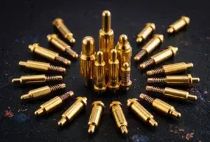
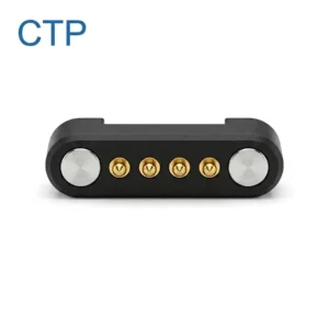
A magnetic pogo pin connector does not make a PLC module hot-swappable by itself. Hot-swap capability belongs to the complete module and backplane system, including the connector contact sequence, module detection, inrush-current control, power switching, fault protection, mechanical seating, communication recovery and controller behavior. Magnets may assist module alignment, while spring-loaded contacts provide electrical compliance, but the system must remain safe and predictable during every insertion and removal state.
A magnetic pogo pin connector does not make a PLC module hot-swappable by itself. Hot-swap capability belongs to the complete module and backplane system, including the connector contact sequence, module detection, inrush-current control, power switching, fault protection, mechanical seating, communication recovery and controller behavior. Magnets may assist module alignment, while spring-loaded contacts provide electrical compliance, but the system must remain safe and predictable during every insertion and removal state.
Modular PLC and distributed I/O systems may allow selected modules to be inserted or removed while other parts of the control system remain powered. This can reduce the amount of equipment that must be stopped during maintenance, but the capability is platform-specific and must be explicitly supported by the controller, backplane and module design.A custom magnetic pogo pin interface may be considered where the project requires repeated module replacement, reduced insertion effort, controlled alignment or a connector geometry developed around a compact cabinet architecture.
Engineers evaluating the general construction of these interfaces can first review the
spring-loaded magnetic connector architecture guide
.Hot-Swap Is a System Capability, Not a Connector Feature
Hot-swap, hot-plug and removal or insertion under power describe controlled system behaviors. They do not mean that any module can be pulled from any energized PLC rack.

The complete system must define what happens electrically, mechanically and logically while the module moves between the disconnected and operating states.| System Element | Role in Hot-Swap Operation | Failure Risk if Not Coordinated |
|---|---|---|
| Connector interface | Provides contact sequencing, electrical paths and physical mating | Short circuits, uncontrolled contact order or intermittent connection |
| Mechanical guides and stops | Control approach, orientation and final working stroke | Offset mating, uneven contact compression or connector damage |
| Backplane | Distributes power and communication to the installed modules | Disturbance of adjacent modules or loss of bus operation |
| Hot-swap power circuit | Controls inrush current, voltage ramp and fault isolation | Supply collapse, arcing, excessive current or component damage |
| Module detection | Confirms module presence, identity and seated condition | Power applied to an incorrect or partially inserted module |
| Controller and firmware | Handles module loss, configuration, alarms and reintegration | Unexpected process behavior or unresolved configuration errors |
| Maintenance procedure | Defines which modules may be replaced and under what conditions | Unsafe or unsupported field operation |
Engineering Note:
Do not describe a connector as a “hot-swap connector” unless the approved module and backplane architecture defines how power, signals and faults are controlled during insertion and removal.
Do not describe a connector as a “hot-swap connector” unless the approved module and backplane architecture defines how power, signals and faults are controlled during insertion and removal.
First Define Which PLC Modules May Be Replaced Online
The maintenance strategy should be established before the connector layout is developed. Different module classes create different system consequences.| Module Type | Primary Hot-Swap Questions |
|---|---|
| Digital input module | How does the controller interpret the loss of field inputs, and what process state is required? |
| Digital output module | What happens to the controlled loads when the output module is removed? |
| Analog I/O module | How are open channels, sensor power and process values handled during replacement? |
| Communication module | How are network connections, addresses and configuration restored? |
| CPU or controller module | Does the architecture provide redundancy or another method of maintaining control? |
| Power module | Is the supply redundant, isolated and designed for live replacement? |
| Safety-related module | Is online replacement permitted within the approved safety architecture? |
A module that can be physically removed is not necessarily approved for removal during operation. The product documentation, control-system architecture and site procedure must all permit the maintenance action.Define the Complete Insertion and Removal State Machine
A PLC module does not move directly from disconnected to fully operational. It passes through several credible mechanical and electrical states.| State | Possible Connector Condition | Recommended System Behavior |
|---|---|---|
| Disconnected | No valid module detected | Module power path remains disabled or controlled according to the approved architecture |
| Approaching | Magnets or guides begin influencing module position | No assumption of valid electrical contact |
| Initial contact | One or more contacts touch before the module reaches the stop | Main load power should not be enabled only because contact is detected |
| Detection or pre-charge | Defined detection contacts or sequencing features become valid | Controller or hot-swap circuit evaluates module identity and power conditions |
| Fully seated | Mechanical stop and required contacts are within the approved position | Power ramp and communication initialization may begin |
| Operating | Module is powered, configured and communicating | System monitors current, voltage, communication and faults as required |
| Removal initiated | Latch, detection contact or module position changes | Outputs, communication and power should transition according to the approved sequence |
| Partial separation | Contacts begin opening in a defined or tolerance-dependent order | Stored energy and live-contact separation must remain controlled |
| Fault | Short circuit, incorrect module, contamination or invalid seating | Power remains disabled or is removed and the controller reports the condition |
Every state should be analyzed at minimum, nominal and maximum mechanical tolerances. A contact sequence that works in the nominal CAD position may change after housing variation, PCB movement or contact wear.Contact Sequencing Can Support Hot-Swap, but It Cannot Complete It
Staggered contact heights, different pogo pin working heights or stepped mating targets may be used to create an intended contact order.Possible sequencing functions include:
- Reference or protective contact established before other circuits
- Module-presence detection
- Pre-charge or power-enable control
- Module identification
- Main power connection
- Communication or signal connection
A First-Mate-Last-Break arrangement is one established connector method for creating an earlier and later contact function. However, staggered contacts alone do not regulate the inrush current, isolate a short circuit or supports that the power contact opens without electrical stress.

The actual sequence must be verified across:- Contact-height tolerances
- Module tilt during insertion
- Guide and rail tolerances
- Housing deflection
- Pogo pin compression variation
- Target-pad height and flatness
- Mechanical wear
- Contamination on the mating surface
Inrush Current Is a Power-Control Problem
A removable module may contain input capacitors, DC/DC converters and local load circuits. When an uncharged module is connected to an energized backplane, the initial charging current can be much higher than its normal operating current.

Excessive inrush current may:- Cause the backplane voltage to dip
- Reset adjacent modules
- Stress connector contacts
- Trigger upstream protection
- Damage the module power path
- Create electrical stress during partial contact
A hot-swap power circuit may use a controlled MOSFET, soft-start behavior, current limiting, undervoltage or overvoltage monitoring and fault shutdown. The selected method depends on the backplane voltage, module capacitance, normal current, fault current and permitted start-up time.
Engineering Note:
The connector should provide the required physical contact paths, but the active power-control circuit must regulate how the module is energized.
The connector should provide the required physical contact paths, but the active power-control circuit must regulate how the module is energized.
Separate Module Alignment from Module Retention
Magnetic attraction may reduce the precision required during the final approach, but it should not be the only structure controlling a PLC module inside a control cabinet.

A preferred mechanical architecture may include:- DIN-rail or chassis guidance
- Side rails or card guides
- Mechanical keys
- A defined end stop
- A release lever or service handle
- A latch where vibration or cable loads require positive retention
- Magnetic capture only in the final mating region
The preferred load path is:

Module housing → rail or chassis guide → control-cabinet structure

rather than:

Module load → magnets → pogo pins → solder joints → PCB

The magnets may assist final positioning, while the cabinet structure carries module weight, insertion force, cable load and vibration.
Define the PLC Module Pin Map Before Choosing the Contact Count
A hot-swap interface often requires more contacts than the normal operating circuit alone would suggest.| Possible Contact Function | Engineering Question |
|---|---|
| Power input | When is it energized and how is inrush current limited? |
| Power return | What return path exists during each mating state? |
| Reference or protective contact | Must it make before and break after other contacts? |
| Module detection | Does the contact indicate initial presence or full seating? |
| Module identification | How does the system reject an incorrect module type? |
| Power enable | Which condition authorizes the module power path? |
| Communication | What protocol, topology and electrical channel are required? |
| Diagnostic or service contact | Is additional monitoring required during insertion or operation? |
The final contact count should be derived from these independent functions. A high pin count alone does not establish hot-swap capability or communication performance.

When the required Pin Map or connector structure remains uncertain, use the

    magnetic pogo pin connector selection guide
.
Partial Mating Is the Critical Electrical Risk
The connector must be evaluated in every credible offset and tilted position, not only when fully seated.| Partial-Mating Condition | Possible Risk | Required Review |
|---|---|---|
| One edge enters first | Contact order differs from the intended sequence | Guide geometry and earliest possible contact |
| One pogo pin touches first | Power or signal is applied without a valid return path | Pin-height variation and target position |
| Module is laterally offset | One pin contacts an adjacent pad or conductive feature | Contact spacing and credible offset envelope |
| Incorrect module is inserted | Wrong power or signal allocation | Mechanical coding and electrical identification |
| Magnetically retained but not seated | Intermittent contact or false module detection | Independent full-seating detection |
| Module is withdrawn under load | Live-contact separation and communication interruption | Power-removal timing and stored-energy discharge |
Mechanical keying, asymmetric contact layouts, insulated barriers, recessed contacts, module identification and controlled power enable may be combined. No single feature should automatically be described as eliminating every insertion error.High-Speed Communication Requires Channel-Level Design
A multi-pin pogo array can provide multiple independent signal paths, but it does not automatically support an industrial Ethernet or high-speed backplane protocol.

Where the interface carries time-sensitive or high-frequency communication, review:- Differential-pair geometry
- Signal-return allocation
- Contact and pad arrangement
- PCB trace impedance
- Crosstalk between adjacent channels
- Common-mode discontinuities
- Shield and chassis strategy
- Connector-to-backplane transition
- Complete channel length
- Behavior while contacts make and break
Signal integrity should be validated for the complete module and backplane channel. A contact-resistance value or pin count alone is insufficient to prove protocol compatibility.Evaluate the Complete Power and Thermal Path
The connector current path may include:- Backplane supply
- Protection and hot-swap circuit
- Backplane copper
- Connector termination
- Pogo pin internal path
- Mating target
- Module PCB copper
- Local power converter
Define:- Backplane voltage
- Normal module current
- Peak and start-up current
- Input capacitance
- Permitted voltage drop
- Permitted temperature rise
- Cabinet ambient temperature
- Adjacent-module heat
- Airflow and enclosure conditions
- Normal and fault operating states
If multiple pogo pins are connected in parallel, equal current sharing should not be assumed. Contact compression, resistance, target flatness and PCB routing may cause one path to carry more current than another.Control-Cabinet Contamination Changes the Connector Risk
Control cabinets may contain dust, wire fragments, oil mist, moisture or metallic particles introduced during installation and maintenance.

Magnetic interfaces require particular attention to ferrous debris because steel particles may be attracted toward the mating region.
Possible effects include:
- Incomplete module seating
- Bridging between adjacent contacts
- Scratching or wear of target pads
- Variation in the magnetic air gap
- False detection of a seated module
- Intermittent power or communication
Possible design responses include:
- Accessible and inspectable mating surfaces
- Recessed or shielded magnetic parts
- Contact spacing based on credible debris size
- Controlled electrical state while unmated
- Protective covers for unused slots
- Maintenance and cleaning instructions
- Slot-level diagnostics
For a broader review of vibration, contamination, service access and cable routing, continue to the

    industrial magnetic connection application guide
.
Design the Technician Workflow
A hot-swap interface should be evaluated as a maintenance operation, not only as an electrical connection.- The controller identifies the affected module and process condition.
- The system confirms that online replacement is permitted.
- The technician identifies the correct slot and replacement module.
- Outputs or dependent functions move to the defined maintenance state.
- The module latch or release mechanism is operated.
- The system detects removal and disables or isolates the power path as required.
- The old module is removed without loading adjacent modules.
- The replacement module enters the mechanical guides.
- Detection, identification and power sequencing are completed.
- The controller verifies configuration and communication.
- The module returns to the approved operating state.
The cabinet layout should provide enough space for gripping, release and module extraction without pulling nearby cables or disturbing adjacent modules.When May a Magnetic Pogo Pin Interface Be Appropriate?
| Project Condition | Potential Value of a Magnetic Pogo Pin Interface |
|---|---|
| Repeated module removal | Spring-loaded contacts can provide compliant repeated mating when validated for the application |
| Limited insertion access | Magnetic capture may assist final positioning inside a constrained cabinet |
| Custom Pin Map | Power, detection, identification and signals can be arranged for the system architecture |
| Flat backplane target | Target pads may allow accessible inspection and replacement |
| Custom module dimensions | The connector housing can be developed around the module and rail structure |
| Defined release workflow | Magnetic retention can be coordinated with a service handle or latch |
When May a Conventional Backplane Connector Be More Appropriate?
A traditional guided backplane connector may remain the better choice when the project requires:- A positive mechanical lock with no intended breakaway
- A standardized PLC or rack ecosystem
- A highly controlled multi-level contact sequence
- A qualified high-speed backplane interface
- Very high contact density in a fixed module pitch
- Protection from exposed contact pads
- Operation in environments with significant ferrous contamination
- Compatibility with existing field-replacement procedures
Magnetic mating should be selected because it solves a defined mechanical or service problem, not because it is assumed to be universally superior to a guided backplane connector.Information Required for a Custom PLC Module Interface
| Requirement Group | Information to Provide |
|---|---|
| PLC architecture | Controller, backplane, module type and permitted online-replacement behavior |
| Module function | Power, I/O, communication, CPU, safety or another function |
| Pin Map | Power, return, detection, identification, control and communication contacts |
| Power | Voltage, normal current, inrush current, input capacitance and fault limits |
| Communication | Protocol, data rate, topology, return paths and channel requirements |
| Mechanical | Module dimensions, guide structure, insertion path, stop position and latch |
| Contact sequence | Required first-mate, detection, power-enable and last-break functions |
| Environment | Cabinet temperature, vibration, dust, oil, humidity and metal-particle exposure |
| Maintenance | Expected replacement frequency, technician access and service procedure |
| Validation | Required electrical, mechanical, EMC and system-level tests |
| Project files | Backplane schematic, PCB layout, module drawing, 3D model and timing diagram |
Recommended Engineering Validation
| Requirement | Recommended Evaluation |
|---|---|
| Mechanical fit | Module, guides, stops, latch and connector dimensional inspection |
| Working stroke | Minimum, nominal and maximum pogo pin compression |
| Contact sequence | Earliest and latest contact positions across assembly tolerances |
| Partial mating | Tilted, offset, reversed and one-contact-first conditions |
| Inrush behavior | Current, voltage dip, power ramp and adjacent-module disturbance |
| Fault isolation | Short circuit, incorrect module, overcurrent and failed power-up |
| Module detection | Presence, full seating, identification and removal timing |
| Communication | Initialization, interruption, recovery and complete channel performance |
| Temperature | Connector, PCB and power-path temperature under defined cabinet conditions |
| Movement and vibration | Continuity or resistance monitoring during the approved equipment profile |
| Contamination | Representative dust, metallic particles and maintenance residue |
| Repeated replacement | Project-defined insertion and removal cycles with post-test inspection |
| System recovery | Controller alarms, configuration, process state and reintegration behavior |
| EMC | Verification at product level according to the applicable control-equipment requirements |
Common Design Mistakes
| Mistake | Possible Consequence | Better Approach |
|---|---|---|
| Calling the connector hot-swappable | The connector is mistaken for a complete system solution | Define the approved module, backplane, power circuit and software behavior |
| Using contact sequencing without inrush control | Backplane voltage disturbance or contact stress | Coordinate the contact sequence with an active power-control circuit |
| Enabling power at initial magnetic contact | Power may be applied before full seating | Use independent seating validation and controlled authorization |
| Using magnets as the module support | Load is transferred into pogo pins, solder joints or PCB | Use guides, rails, stops and a chassis load path |
| Assuming pin count proves data capability | Communication errors or failed EMC performance | Validate the complete signal channel and return structure |
| Ignoring incorrect-module insertion | Wrong power or signal allocation | Combine mechanical coding with electrical identification |
| Ignoring ferrous debris | Contact bridging or incomplete seating | Design for inspection, cleaning and controlled unmated contacts |
| Publishing universal replacement-time or reliability claims | The statement cannot be supported across systems | Measure the actual cabinet workflow and approved test configuration |
Engineering Reference Sources
The applicable product documentation, standard editions and acceptance criteria should be confirmed for the final PLC or industrial-control project.-
Rockwell Automation — Removal and Insertion Under Power
-
Siemens — Module Replacement During Operation with an Active Backplane Bus
-
Analog Devices — Hot-Swap Controller with Inrush-Current and Fault Control
-
Analog Devices — Hot-Swap Power Control for Live Backplanes
-
Molex — First-Mate-Last-Break Contact Configuration Example
-
IEC 61131-2 — Programmable Controllers: Equipment Requirements and Tests
Frequently Asked Questions
Does a magnetic connector make a PLC module hot-swappable?
No. The connector may support alignment, contact sequencing and repeated mating, but hot-swap capability depends on the complete backplane, power-control circuit, module design, controller behavior and approved maintenance procedure.Can PLC modules always be removed while the cabinet remains powered?
No. Only modules and systems explicitly designed and documented for online replacement should be inserted or removed under power.What is First-Mate-Last-Break in a PLC module connector?
It is a contact-sequencing method in which a defined contact is intended to engage before and disengage after other contacts. The sequence must be verified across connector and module tolerances.Does First-Mate-Last-Break eliminate electrical arcing?
No. Contact sequencing may support a controlled hot-swap architecture, but inrush current, stored energy and fault current still require active circuit control.Why is inrush current important during module insertion?
An unpowered module may initially draw a large current while its input capacitance charges. Without control, this may disturb the backplane supply or stress the module and connector.Can magnetic pogo pin connectors carry PLC communication signals?
They may be designed with signal contacts, but protocol compatibility and signal integrity must be verified across the complete connector, PCB and backplane channel.Should magnets hold the complete PLC module?
Normally the chassis, rail, guide or latch should carry the mechanical load. Magnets may assist final alignment or retention.How should the system detect a fully seated module?
Full seating may be confirmed through a dedicated contact, mechanical switch, identification circuit or another validated method independent of initial magnetic attraction.Can metallic dust interfere with the interface?
Yes. Ferrous particles may be attracted toward the magnets and can prevent seating, damage contact surfaces or bridge adjacent contacts.What information is required for a custom PLC connector review?
Provide the module function, Pin Map, backplane voltage, current, input capacitance, communication requirements, contact sequence, module dimensions, insertion path, environmental conditions and available drawings.Prepare Your PLC Module Interface Project
Review the

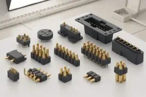
    custom magnetic connector catalog

for existing connector structures, or compare the

    pogo pin connector assemblies

when a magnetic mating system is not required.

Submit the module Pin Map, power conditions, backplane schematic, mechanical structure and available drawings through the

    Get Quote & Samples page
.


    CTP can review the contact allocation, pogo pin working stroke, mating targets, magnetic alignment, mechanical guides and PCB integration. Final hot-swap behavior, power sequencing, communication recovery and PLC-system approval remain the responsibility of the complete equipment design and validation process.
CTP ENGINEERING PATHS
Choose the right path for your project
Move from application requirements to a connector pair, a data-capable cable assembly, or a charging cable configuration. Final specifications are confirmed against an approved drawing and project validation plan.
01
Magnetic Connectors
Connector geometry, pin layout, mechanical integration and OEM/ODM review.
Engineering overview → 02Magnetic Data Cables
Power and signal allocation, cable exit, interface selection and assembly review.
Cable engineering → 03Magnetic Charging Cables
Browse the complete cable catalog and shortlist a starting structure for customization.
View cable catalog →