A vibration-resistant magnetic pogo pin connector must be designed and validated as a complete electromechanical system. Stable operation depends on working stroke, contact-force margin, magnetic retention, housing stiffness, cable restraint, mating-pad support and dynamic electrical monitoring. A static continuity or resistance measurement alone cannot demonstrate vibration performance.
A magnetic pogo pin connector can pass static continuity testing and still experience intermittent power or signal loss during vibration. The problem may not be a defective pogo pin. Dynamic failures can originate from insufficient compression, relative movement at the contact surface, PCB deflection, cable loading, housing resonance, magnet displacement or cracked terminations.
For this reason, vibration resistance should not be represented by one magnetic-force value, one spring-force value or a general statement such as “shock-proof.” Engineers should define the actual mechanical input, mounting condition, electrical load, monitoring method and acceptance criteria for the completed assembly.
This guide explains how to design and validate a vibration-resistant magnetic pogo pin connector without relying on unsupported assumptions about magnet grade, contact force or universal vibration limits.
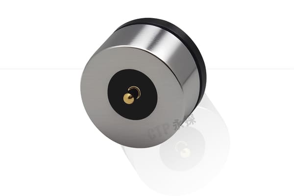
What Does Vibration Resistance Mean for a Magnetic Connector?
Vibration resistance means that the connector maintains its required electrical and mechanical functions while exposed to the vibration conditions defined for the application.
The required functions may include:
- Maintaining continuous power delivery
- Keeping contact resistance within an approved range
- Preventing momentary open circuits
- Maintaining stable detection or control signals
- Keeping the connector fully seated
- Preventing pogo pin sticking or mechanical damage
- Maintaining magnet, housing and insert retention
- Protecting cable and PCB terminations
These requirements should be measurable. The phrase “no disconnection” is incomplete unless the project defines:
- What voltage or resistance condition counts as a disconnection
- The maximum permitted interruption duration
- The monitoring bandwidth or sampling capability
- Whether every individual channel is monitored
- Whether the connector is powered during vibration
- The vibration profile and mounting orientation
Static Contact Resistance and Dynamic Stability Are Different
A static resistance measurement is normally taken while the connector is stationary and fully seated. It can confirm the electrical condition at that moment, but it does not show what happens when the assembly moves.
Dynamic vibration may cause:
- Temporary loss of normal force
- Contact bounce
- Relative sliding between the pogo pin and target pad
- Housing or PCB deflection
- Cable movement that changes the mating angle
- Momentary separation of one contact
- Resistance fluctuations below the threshold of a basic continuity tester
| Measurement | What It Shows | What It May Miss |
|---|---|---|
| Static continuity | Whether a conductive path exists while stationary | Short interruptions and resistance instability |
| Static contact resistance | Resistance at a defined working position | Dynamic contact bounce and cable-induced movement |
| Dynamic resistance monitoring | Resistance variation during vibration or motion | May require suitable bandwidth and fixture control |
| Contact-disturbance monitoring | Momentary electrical interruption under dynamic conditions | Does not independently identify the physical root cause |
| Post-test resistance | Permanent change after exposure | Temporary failures that occurred only during vibration |
A complete validation plan may therefore require measurements before, during and after vibration.
Define the Actual Vibration Environment First
“Industrial vibration” and “automotive vibration” are not complete engineering inputs. The vibration source, frequency content, amplitude, direction, duration and installation condition should be defined.
Common sources include:
- Vehicle engines and road inputs
- Electric motors
- Pumps and compressors
- Fans and rotating equipment
- Robotic movement
- Repeated handheld impacts
- Equipment transportation
- Tool or machinery operation
- Cable movement transferred into the connector
Important project inputs include:
| Vibration Input | Engineering Question |
|---|---|
| Frequency range | Which frequencies are present in the actual equipment? |
| Acceleration or displacement | What mechanical severity reaches the connector location? |
| Vibration type | Is the input sinusoidal, random, transient or mixed? |
| Axes | Which connector directions receive the mechanical load? |
| Duration | Is the exposure continuous, periodic or limited to transportation? |
| Mounting location | Is the connector installed on a rigid frame, PCB, cable or flexible housing? |
| Electrical state | Is the connector powered, carrying data or inactive during exposure? |
| Temperature | Does vibration occur at room temperature or at environmental limits? |
The vibration requirement should be based on the connector’s actual installation rather than copied from an unrelated product category.
Common Dynamic Failure Mechanisms
1. Insufficient Minimum Working Stroke
The connector may operate correctly at nominal dimensions but lose contact force at the minimum-compression tolerance condition.
This can result from variation in:
- Pogo pin free height
- Housing height
- PCB thickness and position
- Mating-pad height
- Mechanical-stop position
- Adhesive or overmolding thickness
- Connector flatness
During vibration, even a small additional deflection may temporarily move the contact below its stable working range.
2. Uneven Compression Across Multiple Pins
In a multi-pin connector, some contacts may be compressed more than others.
Possible causes include:
- Angular mating
- Housing warpage
- PCB bending
- Magnet-position variation
- Foreign material on the mating surface
- Pin-height tolerance
The contact with the lowest compression is normally the most vulnerable to dynamic interruption.
3. Contact Bounce
Contact bounce occurs when dynamic movement causes repeated short separations or changes in contact pressure.
The effect may appear as:
- Momentary open circuits
- Resistance spikes
- Device resets
- Charging interruptions
- Communication errors
- False docking or detection signals
A low-speed meter may not capture short events. The monitoring system should therefore be selected according to the maximum permitted interruption duration.
4. Relative Micro-Movement at the Contact Surface
Vibration can create small relative movement between the plunger tip and target pad even when the connector remains visibly seated.
Repeated micro-movement may contribute to:
- Surface wear
- Resistance instability
- Wear-debris generation
- Damage to the contact finish
- Fretting-related degradation under applicable conditions
The objective is not always to make movement absolutely zero. The design should keep movement within a controlled range and verify that electrical performance remains acceptable.
5. Cable-Induced Loading
The external cable can apply additional dynamic load to the magnetic interface.
Important variables include:
- Cable mass
- Cable length
- Cable exit direction
- Bend radius
- Strain-relief stiffness
- Distance to the first cable support
- Vibration of the surrounding structure
A connector tested without its production cable may behave differently from the completed assembly.
6. PCB or Housing Resonance
The connector may be mounted on a PCB, bracket or housing that amplifies motion at certain frequencies.
Potential effects include:
- PCB bending
- Changing pogo pin compression
- Solder-joint loading
- Housing movement
- Magnet air-gap variation
- Localized acceleration greater than the vibration-table input
A sine sweep can help identify resonant behavior before a longer-duration vibration test.
7. Magnet or Insert Movement
Dynamic loading may affect:
- Magnet adhesive
- Mechanical magnet retention
- Connector insert retention
- Housing fasteners
- Press-fit contacts
A small change in magnet position or air gap can reduce holding force or change final alignment.
8. PCB, Wire or Cable-Termination Failure
The pogo pin interface may remain stable while another part of the electrical path becomes intermittent.
Possible locations include:
- PCB solder joints
- FPC joints
- Wire soldering
- Crimped terminals
- Welded conductors
- Cable strain relief
- External USB or power connectors
The complete path should be divided into measurable sections during failure analysis.
Step 1: Map the Mechanical Load Path
Identify how vibration travels from the equipment into the connector.
A typical load path may be:
Machine or vehicle structure → mounting bracket → device housing → PCB → connector housing → pogo pins and target pads
For a cable assembly, another path may be:
Machine or vehicle structure → cable clips → cable mass → strain relief → magnetic connector
The design review should identify:
- Which part is fixed
- Which part can move
- Where compliance is intended
- Where load is transferred into the PCB
- Whether the cable acts as an additional moving mass
- Whether the connector is near a structural resonance
Step 2: Control the Working-Stroke Window
Calculate pogo pin compression at minimum, nominal and maximum assembly conditions.
| Stroke Condition | Dynamic Risk | Required Review |
|---|---|---|
| Minimum compression | Loss of contact pressure during vibration | Dynamic resistance and interruption monitoring |
| Nominal compression | Insufficient margin if the system deflects | Force, resistance and housing movement |
| Maximum compression | Mechanical bottoming, wear or high structural load | Over-travel, PCB load and mechanical stop |
| Uneven compression | One channel becomes dynamically unstable | Pin-by-pin stroke and resistance comparison |
The approved design should include enough margin for dimensional tolerance and expected dynamic deflection without allowing excessive compression.
Step 3: Provide a Controlled Mechanical Stop
The magnets should bring the connector halves together, but a mechanical stop should define the final seated position.
Without a controlled stop:
- Pogo pin compression may depend on magnet force
- Housing deformation may change the working stroke
- Different samples may seat at different positions
- Vibration may allow repeated movement around the final location
The stop should be:
- Located near the contact interface
- Sufficiently stiff
- Dimensionally controlled
- Supported by the housing rather than only by PCB solder joints
- Included in the assembly tolerance stack
Step 4: Use Housing Geometry to Control Lateral Movement
Magnetic attraction alone does not ensure that the connector remains laterally stable.
Mechanical locating features may include:
- Recessed mating surfaces
- Locating bosses
- Guide walls
- Asymmetric housings
- Keys or anti-rotation features
- Controlled contact-pad clearances
The geometry should provide enough guidance to control vibration-induced sliding without creating an excessively tight fit that prevents normal magnetic mating.
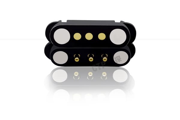
Step 5: Balance Retention and Release Requirements
The connector must remain seated during the expected vibration input, but it may also need to release safely when the cable or device is pulled.
These are separate requirements:
- Minimum axial holding force
- Minimum lateral stability
- Cable-peel release behavior
- Maximum acceptable user separation force
- Retention after temperature or environmental exposure
The net holding margin depends on:
- Magnetic force at the assembled air gap
- Total pogo pin spring force
- Seal or gasket reaction
- Dynamic external loading
- Housing and cable geometry
The detailed force calculation belongs in the connector force-budget review. Vibration validation should confirm that the completed force system remains stable under actual dynamic loading.
Step 6: Support the PCB and Target Pad
The mating pad and PCB should not move excessively under the combined pogo pin and vibration load.
Review:
- PCB thickness
- Distance from the connector to mounting screws or supports
- Target-pad location
- Board cutouts
- Flexible sections
- Enclosure contact points
- Connector reaction-force path
A mechanically unsupported PCB can bend during vibration and change the compression of the pogo pins.
Where the connector load is significant, the reaction should be transferred into:
- The device housing
- A rigid bracket
- Mechanical supports near the connector
- A controlled insert structure
Do not rely only on solder joints to absorb repeated mechanical loading.
Step 7: Design the Cable and Strain Relief as Part of the System
A cable-connected magnetic interface should be tested with the actual production cable.
Define:
- Cable length
- Conductor size
- Outer diameter
- Jacket material
- Bend radius
- Exit angle
- Strain-relief length and stiffness
- Distance to the first cable clamp
Possible design controls include:
- Supporting the cable close to the connector
- Avoiding a heavy unsupported cable loop
- Separating cable movement from the connector mating surface
- Controlling the cable bend direction
- Using an appropriate flexible strain relief
- Avoiding resonance of the cable assembly
Step 8: Select the Contact Tip and Target Pad as a Pair
The plunger tip and target pad influence dynamic electrical behavior.
Review:
- Tip shape
- Local contact pressure
- Target-pad size
- Surface finishes
- Expected sliding distance
- Wear pattern
- Contamination conditions
A concentrated tip may provide higher local pressure but can increase pad wear. A broader tip may distribute force but respond differently to contamination or angular movement.
The correct combination should be confirmed with:
- Contact resistance measurements
- Dynamic resistance monitoring
- Wear inspection
- Post-vibration surface analysis
Step 9: Evaluate Powered Vibration Where Required
Unpowered vibration can identify mechanical weaknesses, but it may not reproduce every electrical condition present during actual use.
Where the connector normally carries power during vibration, evaluate:
- Operating current
- Voltage drop
- Temperature rise
- Momentary interruption
- Resistance variation
- Device restart or charging behavior
A connector can remain mechanically intact but still experience unacceptable resistance fluctuations under load.
The test plan should specify whether current is:
- Applied continuously
- Applied only during selected test stages
- Used only as a low-level monitoring signal
- Representative of the maximum device load
Step 10: Monitor Each Critical Channel
Monitoring only the combined power path may hide one unstable contact in a multi-pin connector.
Where practical, monitor:
- Each power contact
- Each parallel current path
- Ground contacts
- Docking-detection contacts
- Critical signal contacts
For every channel, define:
- Baseline resistance
- Maximum permitted variation
- Open-circuit threshold
- Maximum permitted interruption duration
- Monitoring rate or bandwidth
- Data-recording method
A test system should be capable of detecting the event duration defined by the product requirement.
Building a Vibration Validation Plan
1. Freeze the Test Configuration
Document:
- Connector part number and revision
- Sample lot
- PCB and cable revision
- Housing and mounting structure
- Working stroke
- Magnetic air gap
- Electrical load
- Monitoring method
- Failure criteria
2. Record Baseline Measurements
Before vibration, record:
- Visual condition
- Connector dimensions
- Pogo pin free and working height
- Spring force where required
- Magnetic holding and separation force
- Static contact resistance
- Voltage drop and temperature rise where applicable
3. Use the Final or Representative Mounting Structure
The specimen should be mounted using a configuration that represents the intended device.
The fixture should not:
- Artificially stiffen a flexible housing
- Clamp the connector in a way not present in the product
- Remove the cable mass
- Add excessive movement unrelated to the application
- Hide a PCB or bracket resonance
4. Identify Resonances
A controlled sine sweep may help identify frequencies at which the assembly response increases.
Observe:
- Connector movement
- PCB or bracket deflection
- Cable motion
- Resistance variation
- Contact interruptions
- Unexpected noise or mechanical looseness
5. Apply the Project Vibration Profile
Depending on the application, the validation may use:
- Sinusoidal vibration
- Broadband random vibration
- Application-recorded vibration data
- Vehicle or machinery-specific mechanical loads
- Combined vibration and temperature conditions
The selected profile should be traceable to the actual use condition or an approved product requirement.
6. Test All Relevant Axes
A connector can behave differently under:
- Axial vibration
- Lateral vibration
- Vibration aligned with cable movement
- Vibration normal to the PCB
The axes should be defined relative to the connector and its installation.
7. Include Mechanical Shock Where Relevant
Shock events may come from:
- Vehicle impacts
- Device drops
- Machine stops
- Tool impacts
- Docking collisions
- Transportation handling
Shock and vibration should not be treated as identical tests. Shock normally represents shorter transient loading, while vibration represents repeated or continuous dynamic loading.
8. Repeat Post-Test Measurements
After exposure, repeat the baseline inspection and compare each individual sample.
Check for:
- Permanent resistance change
- Spring-force change
- Reduced magnetic holding force
- Plunger sticking
- Housing cracks or movement
- Magnet displacement
- PCB solder-joint damage
- Cable or strain-relief damage
- Target-pad wear
Example Vibration Test Matrix
| Test Stage | Purpose | Measurements |
|---|---|---|
| Initial inspection | Establish sample condition | Dimensions, resistance, force and visual condition |
| Sine sweep | Identify resonance and sensitive frequencies | Dynamic resistance, motion and fixture response |
| Sinusoidal or random vibration | Evaluate operation under the specified mechanical input | Contact disturbance, resistance variation and electrical function |
| Powered vibration | Evaluate dynamic operation under electrical load | Voltage drop, current, temperature and interruption events |
| Mechanical shock | Evaluate short transient loading | Continuity, retention and physical condition |
| Post-test inspection | Identify permanent degradation | Resistance, force, dimensions and wear |
Define Failure Criteria Before Testing
A vibration test should not be judged only by whether the connector remains physically attached.
Possible acceptance criteria include:
- No interruption longer than the approved duration
- No resistance excursion above the approved threshold
- No device reset or charging interruption
- No pogo pin sticking
- No magnet, insert or housing displacement
- No solder-joint or cable-termination damage
- Post-test resistance within the approved limit
- Post-test magnetic and spring forces within the approved range
- No unacceptable contact-pad wear
The criteria should be linked to the device function. A short interruption that is acceptable for one charging application may be unacceptable for a control, medical-monitoring or safety-related signal.
How to Investigate a Vibration Failure
When a failure occurs, record:
- Time of occurrence
- Test axis
- Frequency or vibration condition
- Affected electrical channel
- Interruption duration
- Resistance before and after the event
- Electrical load
- Video or motion observation where available
Then divide the investigation into:
| Area | Possible Investigation |
|---|---|
| Pogo pin | Free height, force, return movement and internal damage |
| Working stroke | Minimum compression and dynamic housing deflection |
| Mating pad | Wear position, finish condition and alignment |
| Magnetic structure | Holding force, air gap, polarity and magnet movement |
| Housing | Flatness, resonance, mechanical-stop movement and cracks |
| PCB | Deflection, solder joints and mounting support |
| Cable | Mass, routing, strain relief and conductor continuity |
| Measurement system | Fixture contact, bandwidth, grounding and data acquisition |
A detected electrical interruption should not automatically be attributed to insufficient magnet strength.
Application-Specific Design Considerations
Vehicle-Mounted Devices
Review:
- Actual installation location
- Road and vehicle vibration input
- Cabin or enclosure temperature
- Cable routing
- Mounting-bracket stiffness
- Powered operation during vibration
Industrial Machinery
Review:
- Motor and rotating-equipment frequencies
- Oil, dust and metallic contamination
- Machine-frame resonance
- Continuous duty cycle
- Maintenance and cable replacement
Robotic and Automated Docks
Review:
- Docking approach speed
- Positioning repeatability
- Impact during docking
- Cable or module mass
- Misalignment recovery
- Dynamic contact monitoring during motion
Portable and Handheld Equipment
Review:
- User movement
- Repeated impacts
- Cable snag direction
- Device drops
- Housing flexibility
- Contact contamination
Common Vibration-Resistance Design Mistakes
| Design Mistake | Possible Consequence | Better Approach |
|---|---|---|
| Using magnet grade as proof of vibration resistance | Actual holding force and alignment remain unknown | Measure the completed connector at its assembled air gap |
| Specifying one universal spring-force range | The force may not suit the pin count or mechanical structure | Define force at the project-specific working stroke |
| Checking only static continuity | Momentary interruption is not detected | Monitor resistance or contact disturbance during vibration |
| Testing without the production cable | Cable-induced loading is missed | Use the final cable, strain relief and routing |
| Testing a loose connector on a rigid fixture | PCB and housing resonance are missed | Use a representative device-level assembly |
| Assuming magnets prevent all micro-movement | Contact wear and resistance variation may remain | Control the housing, working stroke and locating features |
| Monitoring only the combined circuit | One unstable pin may be hidden | Monitor critical channels individually |
| Using one vibration profile for every application | The test may not represent field use | Define the profile from installation and product requirements |
| Ignoring test-system bandwidth | Short contact disturbances may not be recorded | Match the monitoring system to the permitted event duration |
| Increasing magnet force as the only corrective action | Removal force and pogo pin compression may become excessive | Investigate the complete mechanical and electrical load path |
Engineering Reference Standards
The applicable edition, test severity, mounting configuration and acceptance criteria should be confirmed for each project.
-
IEC 60512-2-3 — Contact resistance variation under dynamic conditions
-
IEC 60512-2-5 — Contact disturbance under dynamic conditions
-
IEC 60512-6-4 — Sinusoidal vibration testing for connectors
-
IEC 60512-6-3 — Shock testing for connectors
-
IEC 60068-2-64 — Broadband random vibration and guidance
-
IEC 60068-2-27 — Shock testing
-
ISO 16750-3:2023 — Mechanical loads for road-vehicle electrical and electronic equipment
Frequently Asked Questions
Does a stronger magnet make a pogo pin connector vibration-proof?
No. A stronger magnet may increase retention, but vibration performance also depends on working stroke, housing guidance, PCB stiffness, cable loading, contact geometry and the actual assembled air gap.
What is the correct spring force for a vibration-resistant pogo pin?
There is no universal value. The required force depends on the pogo pin design, working stroke, contact function, pin count, target pad, vibration input and total connector-force budget.
Why does a connector pass continuity testing but fail during vibration?
A stationary continuity test may not reproduce contact bounce, housing movement, cable loading, PCB deflection or short resistance excursions that occur under dynamic conditions.
Should the connector be powered during vibration testing?
That depends on actual use. Where the connector normally carries power or signals during vibration, powered or actively monitored testing may be required to reproduce the functional risk.
What is the difference between contact resistance variation and contact disturbance?
Contact resistance variation evaluates changes in the electrical resistance of the interface under dynamic conditions. Contact-disturbance monitoring focuses on detecting momentary interruptions or abnormal electrical events.
Should every pin be monitored separately?
Critical channels should be monitored individually where practical. Monitoring only the combined circuit can hide one unstable contact, especially when several pins are connected in parallel.
Does magnetic mating eliminate fretting corrosion?
No. Magnetic mating may help control positioning, but relative micro-movement, materials, contact force, wear, contamination and the vibration environment still affect the contact interface.
Can the connector be tested without the final enclosure?
Component testing can support early development, but final validation should include a representative PCB, housing, cable, mounting structure and working stroke because these elements affect dynamic behavior.
Is automotive vibration testing suitable for every industrial connector?
No. Automotive, industrial, wearable and transportation applications may have different frequency content, severity, mounting conditions and operating states. The profile should reflect the intended installation.
Prepare a Vibration-Resistance Review
Provide the following information before prototype or validation planning:
- Application and installation location
- Connector Pin Map
- Voltage, current and signal functions
- Pogo pin working-stroke range
- Spring-force requirements
- Magnet arrangement and assembled air gap
- Holding and release-force requirements
- PCB, housing and mounting drawings
- Cable length, weight and routing
- Expected vibration and shock conditions
- Electrical operating state during vibration
- Permitted resistance change
- Permitted interruption duration
- Required test standards and documentation
Review available custom magnetic connector structures, compare pogo pin connector assemblies, access the connector engineering guides, or submit drawings and vibration requirements through the Get Quote & Samples page.
CTP can review the working stroke, force system, housing guidance, PCB support, cable structure and proposed dynamic monitoring method before prototype development. Final vibration profiles, electrical loads and acceptance criteria should be confirmed in the approved project specification.
CTP ENGINEERING PATHS
Choose the right path for your project
Move from application requirements to a connector pair, a data-capable cable assembly, or a charging cable configuration. Final specifications are confirmed against an approved drawing and project validation plan.
Magnetic Connectors
Connector geometry, pin layout, mechanical integration and OEM/ODM review.
Engineering overview → 02Magnetic Data Cables
Power and signal allocation, cable exit, interface selection and assembly review.
Cable engineering → 03Magnetic Charging Cables
Browse the complete cable catalog and shortlist a starting structure for customization.
View cable catalog →