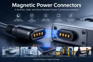
Anti-mismating is one of the most important design requirements for a magnetic pogo pin connector. A connector may align smoothly and feel intuitive to the user, but if it can mate in the wrong orientation, shift onto the wrong pads or energize before the contacts are correctly positioned, it can still create short circuits, damaged contacts or intermittent operation.
A reliable anti-mismating design therefore cannot depend on magnetic attraction alone. It normally combines mechanical geometry, magnetic polarity, contact layout, electrical sequencing and tolerance control.
Self-alignment, blind mating and anti-mismating are related but different functions. Self-alignment helps the two halves find each other. Blind mating allows connection without direct visual access. Anti-mismating prevents an incorrect orientation or offset position from creating an unsafe electrical connection.
What Is an Anti-Mismating Magnetic Pogo Pin Connector?
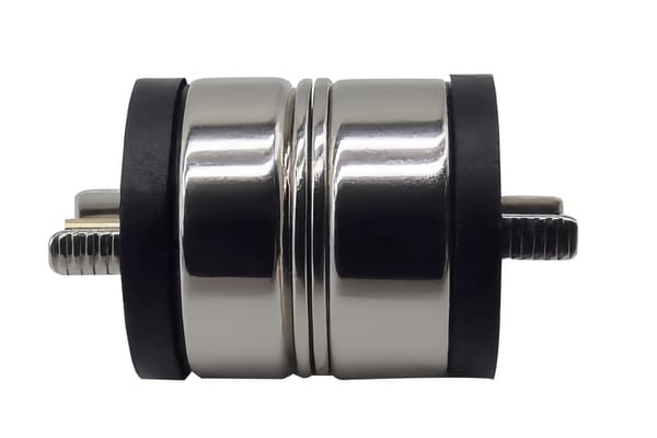
An anti-mismating magnetic pogo pin connector is an electrical interface designed to prevent the two mating halves from making an unsafe connection in the wrong orientation, position or sequence.
A typical assembly may include:
- spring-loaded pogo pins;
- flat or recessed mating pads;
- permanent magnets or magnetic steel components;
- plastic or metal housings;
- mechanical keys, locating walls or guide posts;
- PCB, FPC, wire or cable terminations;
- optional detection, shielding or sealing features.
The pogo pins carry power or signals. The magnets provide attraction and may assist orientation. The housing controls the final position. The PCB pin map determines whether an incorrect partial contact creates a safe condition or an electrical hazard.
Why Incorrect Mating Happens
Incorrect mating is not limited to a connector being rotated 180 degrees. Several failure modes must be considered during design.
| Mating error | Possible consequence |
|---|---|
| Reversed orientation | Power and ground may be exchanged, or signals may connect to the wrong circuits. |
| One-pin or one-row offset | A contact may bridge the wrong pad or energize an unintended input. |
| Angular mating | One side may make contact before the other, creating uneven compression or electrical sequencing. |
| Partial mating | Power may be applied before signal, ground or detection contacts are stable. |
| Side sliding | The pogo pin tips may scrape pads, increase wear or temporarily bridge adjacent contacts. |
| Incorrect accessory mating | Two visually similar products may connect mechanically even though their electrical pin maps are different. |
The design must therefore answer two questions:
- Can the connector physically reach an incorrect position?
- If it does, can any electrical contact occur before the error is blocked?
1. Use Mechanical Keying as the Primary Defense
Mechanical geometry should normally provide the first layer of anti-mismating protection. Unlike magnetic force, a correctly designed key can create a hard physical stop before the pogo pins touch the wrong pads.
Common mechanical keying methods include:
- asymmetrical outer housings;
- different corner radii;
- offset locating posts;
- male-and-female guide walls;
- unequal side lengths;
- recessed contact zones;
- orientation tabs;
- non-symmetrical screw or magnet positions.
A good keying feature should prevent incorrect mating early in the engagement process. The wrong orientation should be stopped before the pogo pins reach a level where they can touch conductive pads.
Keying also needs sufficient strength. Thin plastic tabs can deform, wear or be forced into position by the user. The feature should be reviewed for material strength, molding tolerance, insertion angle and repeated-use durability.
Mechanical keying questions
- At what distance does the wrong orientation become blocked?
- Can the user force the connector past the key?
- Can housing tolerance reduce the effectiveness of the stop?
- Does the key still work when the connector approaches at an angle?
- Can wear or contamination change the mating behavior?
2. Use Magnetic Polarity as an Orientation Aid
Magnet polarity can make the correct orientation feel natural and the incorrect orientation less attractive. For example, a selected pole arrangement may attract in the intended position and repel when the connector is rotated.
This is useful for:
- one-handed docking;
- blind mating;
- charging cables;
- wearable devices;
- handheld instruments;
- replaceable modules.
However, polarity should generally be treated as an orientation aid rather than the only safety control.
Several factors can limit magnetic anti-mismating performance:
- the user may apply more force than the repulsion force;
- the connector may approach from an offset position;
- steel components may alter the magnetic path;
- magnet tolerances may change the force balance;
- small magnets may provide limited directional feedback;
- multiple products may accidentally use compatible magnetic patterns.
The recommended approach is:
Mechanical geometry prevents unsafe contact. Magnetic polarity guides the user toward the correct position. Electrical design limits the consequence if partial contact still occurs.
3. Design the Pin Map for Electrical Safety
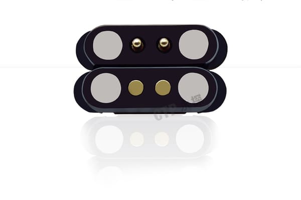
Mechanical protection should be supported by a fault-tolerant electrical pin map. Engineers should consider what happens if the connector is offset, rotated, tilted or only partially engaged.
Useful design methods include:
- placing ground contacts at the outer positions;
- separating power and sensitive signal contacts;
- using duplicate ground contacts around high-current pins;
- keeping adjacent wrong-contact combinations electrically safe;
- using a dedicated identification or detection contact;
- adding current limiting during initial connection;
- keeping high-voltage or high-current contacts recessed;
- using a staged contact sequence where needed.
Check every possible offset condition
For a linear connector, engineers should examine at least:
- correct mating;
- one position left;
- one position right;
- reversed orientation;
- partial edge contact;
- rotated contact;
- contact with a conductive foreign object.
A simple pin-map table can reveal unsafe combinations before tooling begins.
| Design feature | Purpose |
|---|---|
| Outer ground contacts | Can establish a return path before internal power or signal contacts engage. |
| Detection pin | Allows the device to confirm correct mating before enabling power. |
| Recessed power pad | Reduces the probability of power contact during an offset approach. |
| Separated power and data | Reduces the risk of supply voltage reaching a sensitive signal circuit. |
| Current-limited start-up | Limits damage if an abnormal contact occurs during initial mating. |
4. Control Pad Size, Pitch and Contact Exposure
Pad geometry has a major influence on both mating tolerance and short-circuit risk.
Larger pads can increase the allowable positional tolerance, but if adjacent pads are too close, an offset pogo pin may bridge or touch the wrong circuit. Smaller pads reduce the wrong-contact area but require more accurate alignment.
Important parameters include:
- pogo pin tip diameter;
- pad diameter or width;
- center-to-center pitch;
- insulation gap;
- maximum lateral offset;
- plunger tilt;
- housing guide clearance;
- PCB and molding tolerances.
For safety-critical power layouts, exposed conductive areas should be reviewed under all possible positions. Recessed pads, insulating ribs or raised guide walls can reduce accidental bridging.
5. Calculate the Complete Tolerance Stack
A connector that appears properly keyed in CAD may still mate incorrectly if the manufacturing tolerances accumulate in the wrong direction.
The tolerance analysis should include:
- magnet position;
- pogo pin position;
- mating-pad position;
- plastic housing dimensions;
- PCB positioning;
- assembly fixture accuracy;
- adhesive or overmolding movement;
- thermal expansion;
- wear after repeated mating.
The analysis should review both correct and incorrect mating conditions.
Correct-mating tolerance
Every pogo pin should land within the approved pad area and remain inside its working-stroke range.
Incorrect-mating tolerance
The housing should block the connector before any unsafe electrical contact can occur, even at the worst combined dimensional condition.
Prototype testing should include minimum, nominal and maximum tolerance samples where the risk justifies it.
6. Distinguish Anti-Mismating from Fretting Control
Anti-mismating design can reduce damage caused by incorrect insertion, scraping and side loading. It may therefore reduce one source of contact wear.
However, anti-mismating does not eliminate fretting corrosion.
Fretting is generally associated with small repetitive relative movement at the contact interface. It can be influenced by:
- vibration;
- low contact force;
- thermal expansion;
- housing movement;
- surface contamination;
- plating wear;
- oxidation products.
Controlling fretting requires a broader contact-system strategy:
- maintain suitable spring force;
- keep the pogo pins inside the working-stroke range;
- control housing movement;
- select a suitable plating system;
- limit contamination;
- monitor contact resistance during vibration testing;
- inspect surfaces after durability testing.
Therefore, the accurate engineering statement is:
7. Define Retention and Breakaway Force
The magnets must provide enough force to maintain pogo pin compression, but the correct force depends on the application.
The required magnetic retention must be evaluated against:
- total pogo pin spring force;
- gasket or sealing force;
- cable pull;
- device movement;
- vibration and shock;
- desired breakaway behavior;
- user handling requirements.
Too little force may allow intermittent contact. Too much force may make the connector difficult to remove, stress the housing or attract more metallic debris.
Anti-mismating and retention also interact. A strong magnet can pull an offset connector toward the mating face before the keying structure has corrected its position. The guide geometry should therefore control the approach path before the magnetic force becomes dominant.
8. Prevent Arcing During Power Connection
For power connectors, incorrect or partial mating can create arcing if the circuit is energized while the contacts are unstable.
Potential control measures include:
- detecting the connector before enabling the main power rail;
- using pre-charge or current limiting;
- sequencing ground before power;
- keeping power pads recessed;
- preventing sliding across energized pads;
- using multiple contacts only after current-sharing validation;
- testing temperature rise and voltage drop.
The connector should not be assumed safe for hot plugging unless the complete mating sequence and electrical protection circuit have been evaluated.
9. EMI Shielding Is a Separate Design Task
A magnetic pogo pin connector can be integrated into a shielded housing, but the magnets and pogo pins do not automatically provide EMI protection.
A shielding design may need to consider:
- continuous conductive enclosure paths;
- ground contact sequencing;
- shield termination;
- PCB ground layout;
- cable shielding;
- enclosure seams;
- filtering and transient protection;
- signal return paths.
A metal shell may support shielding, but its effectiveness must be evaluated as part of the complete device. The connector should not be described as a Faraday cage unless the assembled structure has been designed and tested for that purpose.
10. Validation Plan for Anti-Mismating Performance
Anti-mismating should be verified through physical testing, not only through CAD review.
| Test | What to verify |
|---|---|
| Reverse-orientation test | Incorrect orientation cannot create unsafe electrical contact. |
| Offset-mating test | One-pin and partial offsets do not bridge unsafe circuits. |
| Angular-approach test | The keying structure controls engagement from realistic approach angles. |
| Forced-mismating test | Reasonable user force cannot overcome or damage the anti-mismating feature. |
| Retention-force test | The connector maintains contact without exceeding the intended detachment force. |
| Mating-cycle test | Keying features, plating and magnetic retention remain functional after repeated use. |
| Vibration test | No unacceptable electrical interruptions or mechanical disengagement occur. |
| Contamination test | Dust or metallic particles do not create unsafe bridging or prevent correct mating. |
| Electrical fault test | Partial or incorrect contact does not expose the device to unacceptable current or voltage. |
Acceptance criteria should be defined before testing. Depending on the application, they may include:
- no contact between prohibited circuits;
- maximum allowable contact-resistance change;
- maximum interruption duration;
- minimum retention force;
- maximum user separation force;
- no visible damage to the keying features;
- no unsafe temperature rise;
- continued correct orientation after durability testing.
Anti-Mismating Design Review Checklist
| Review area | Engineering question |
|---|---|
| Housing | Does the geometry physically block reversed and offset positions? |
| Magnet arrangement | Does polarity guide correct mating without becoming the only safety feature? |
| Pin map | Are all reversed and offset contact combinations electrically safe? |
| Contact sequencing | Should ground, detection or pre-charge contacts engage before main power? |
| Tolerances | Does the design remain safe at minimum and maximum dimensional conditions? |
| Durability | Will wear, deformation or contamination weaken the anti-mismating feature? |
| Fault protection | Can current limiting or connector detection reduce the consequence of a fault? |
When Magnetic Polarity Is Not Enough
Magnetic polarity alone may be insufficient when:
- incorrect mating could connect high current or voltage to the wrong circuit;
- the user can apply substantial mating force;
- several accessories use similar connector shapes;
- the connector is exposed to metal debris;
- positive mechanical locking is required;
- the product must meet a formal safety standard;
- the contact array is dense and the pitch is small;
- an incorrect partial position can energize the system.
In these situations, use mechanical keying, electrical detection and protection circuitry together with the magnetic arrangement.
Information Required for a Custom Design
To evaluate an anti-mismating magnetic pogo pin connector, provide the following information:
- pin count and pin assignment;
- continuous and peak current;
- signal types and data rates;
- available connector dimensions;
- intended mating direction;
- possible incorrect mating orientations;
- required retention or breakaway force;
- maximum allowable contact exposure;
- hot-plugging requirement;
- working stroke and compression target;
- environmental and contamination conditions;
- mating-cycle target;
- PCB, FPC, wire or cable termination;
- 2D drawings, 3D files and enclosure references.
The earlier these inputs are defined, the easier it is to coordinate the magnet layout, housing key, pogo pin geometry and electrical pin map.
Frequently Asked Questions
Can magnet polarity completely prevent incorrect mating?
No. Polarity can guide orientation or create repulsion in an incorrect position, but mechanical keying should be used where wrong contact could create a safety or reliability risk.
Does an anti-mismating design eliminate fretting corrosion?
No. It can reduce abnormal scraping and side loading caused by incorrect insertion. Fretting also depends on vibration, contact force, plating, movement and contamination.
Should power contacts engage before or after detection contacts?
In many applications, a detection or ground contact should engage before the main power path is enabled. The correct sequence depends on the circuit architecture and hot-plugging requirements.
Can a magnetic pogo pin connector be made reversible?
Yes, but the pin map must be electrically symmetrical, or the electronics must detect orientation and route signals safely. A mechanically reversible connector is not automatically electrically reversible.
How can adjacent-pin short circuits be reduced?
Possible methods include increasing insulation spacing, reducing exposed pad area, using recessed contacts, adding guide walls, separating high-risk circuits and verifying all offset mating positions.
Can the same magnetic connector be used across several products?
It can, but the electrical pin map and accessory compatibility must be controlled. Visually compatible connectors with different voltages or pin functions can create a serious mismating risk.
Conclusion
An anti-mismating magnetic pogo pin connector is not created by magnets alone. Reliable protection requires a coordinated mechanical, magnetic and electrical architecture.
Mechanical geometry should block incorrect engagement. Magnetic polarity should guide the connector toward the intended orientation. The pin map and protection circuit should limit the consequence of partial or abnormal contact. Tolerances and durability must then be verified through physical testing.
CTP supports custom development of magnetic pogo pin connectors, magnetic cable assemblies, pogo pin connectors and individual pogo pins.
For a new anti-mismating design, submit your pin map, voltage and current requirements, available space, mating direction and enclosure drawings through our Get a Quote & Samples page. The magnet layout, mechanical keying and electrical protection strategy can then be reviewed before prototype development.
CTP ENGINEERING PATHS
Choose the right path for your project
Move from application requirements to a connector pair, a data-capable cable assembly, or a charging cable configuration. Final specifications are confirmed against an approved drawing and project validation plan.
Magnetic Connectors
Connector geometry, pin layout, mechanical integration and OEM/ODM review.
Engineering overview → 02Magnetic Data Cables
Power and signal allocation, cable exit, interface selection and assembly review.
Cable engineering → 03Magnetic Charging Cables
Browse the complete cable catalog and shortlist a starting structure for customization.
View cable catalog →