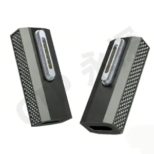
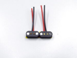
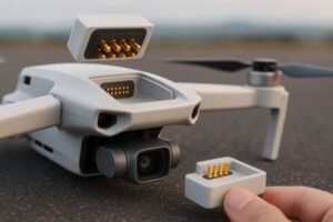
A magnetic charging interface for a handheld beauty device should be designed around the complete use cycle: treatment, cleaning, drying, storage and charging. Engineers must define the device power requirement, charging state, Pin Map, exposed-contact condition, cosmetic residue, cleaning method, enclosure sealing, magnetic force and electrical protection before selecting the connector.
A magnetic charging cable should not be selected for a beauty device only because it has a compact appearance, exposed gold-colored contacts or an advertised IP rating. The connector becomes part of a complete product system that may be exposed to water, skin oils, conductive gels, cosmetic residues, cleaning agents and frequent user handling.
The central engineering question is not simply whether the connector can carry the required charging current. The product team must also determine what happens when the device is wet, when residue remains on the contact surface, when the cable is attached incorrectly and when the user attempts to charge the device immediately after cleaning.
This guide explains how to specify a magnetic charging interface for handheld beauty and skincare devices without relying on universal IP, plating-thickness or corrosion-resistance claims.
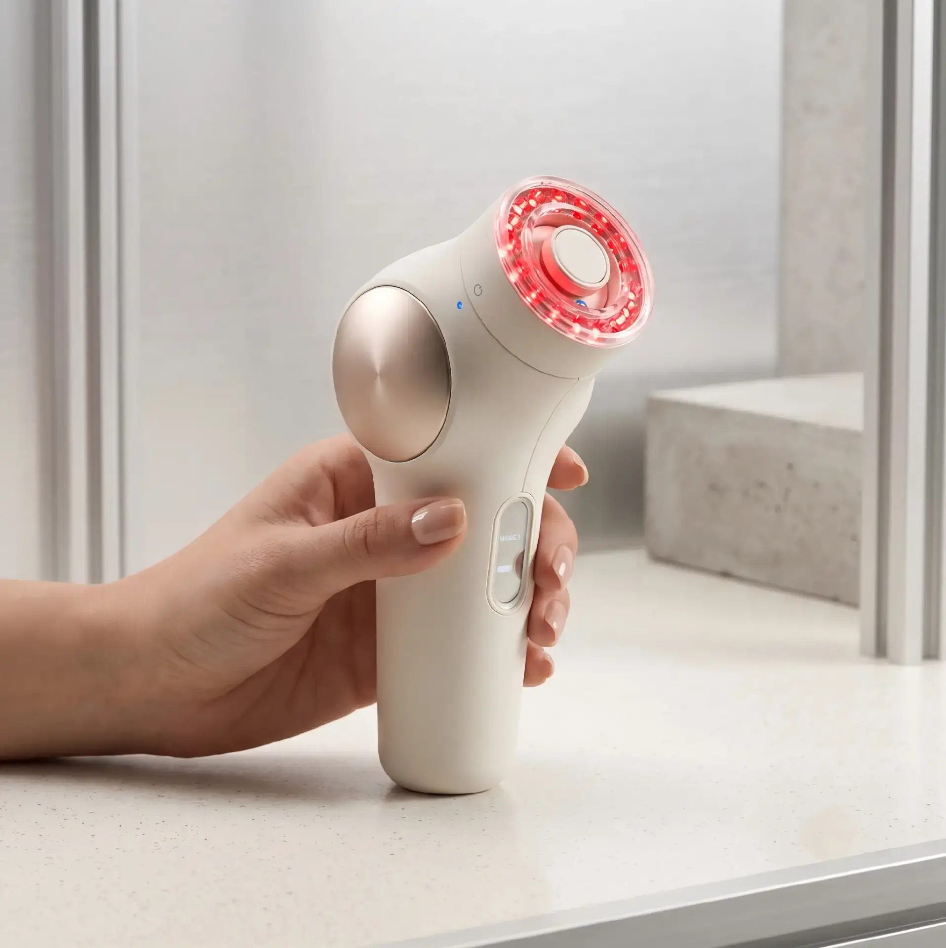
What Is Different About a Beauty-Device Charging Interface?
Many handheld beauty products are used close to the skin, sinks, bathrooms, creams, gels or liquid skincare products. The connector may therefore encounter conditions that are less common in a desktop consumer-electronics product.
Potential exposure includes:
- Water droplets after cleaning
- Condensation from a humid bathroom
- Human sweat and skin oils
- Water-based conductive gel
- Facial serum or lotion
- Oil-based cosmetic products
- Alcohol-based cleaning products
- Detergent or disinfectant residue
- Cotton fibers, dust and cosmetic powder
These substances do not create one universal “corrosion environment.” Their conductivity, viscosity, drying behavior and chemical compatibility can be different. The project should therefore define the actual substances and cleaning procedures expected during use.
Begin with the Complete User Workflow
The charging interface should be designed around the sequence in which the user operates the product.
A typical workflow may include:
- The user removes the device from its charging cable or dock.
- The device is used on the skin with or without gel, serum or another cosmetic product.
- The device surface is wiped, rinsed or cleaned.
- The device is dried or placed in storage.
- The charging connector is attached.
- The charging circuit detects the connection and enables power.
The engineering team should determine whether these steps must occur in this order.
Important questions include:
- Can the user connect the charger immediately after rinsing the device?
- Must the connector surface be dry before charging begins?
- Can the device detect incomplete or contaminated mating?
- Does the charger remain energized when it is not connected?
- Can the device operate while charging?
- Does the product documentation require the connector to be cleaned?
- How can the user confirm that the connector is fully seated?
The safest and most practical charging workflow depends on the complete product design and its applicable safety requirements. It should not be decided from the connector alone.
Define the Operating and Charging States
The product specification should separate the device states rather than using a general statement such as “waterproof during charging.”
| Device State | Possible Condition | Required Engineering Definition |
|---|---|---|
| In use | Device contacts the skin, gel, water or cosmetic product | Is the charging interface exposed, covered or electrically inactive? |
| After use | Residue or moisture may remain on the enclosure | What cleaning and drying procedure is required? |
| Cleaning | Device may be wiped, rinsed or disinfected | Which liquid, chemical, duration and method are permitted? |
| Charging approach | Cable or dock approaches the exposed contact surface | Is the source energized before full mating? |
| Charging | Power passes through the magnetic interface | What voltage, current, temperature and contact condition are permitted? |
| Storage | Device may remain on a dock for an extended period | Does the interface remain powered after the battery is charged? |
Separating these states makes it easier to define electrical protection, enclosure sealing and user instructions.
Step 1: Decide Whether Charging Is Allowed When the Interface Is Wet
The phrase “used in a humid bathroom” does not automatically mean that the product should charge while water is present on the contacts.
Possible design strategies include:
- Requiring the contact surface to be dry before charging
- Keeping the charging contacts electrically inactive until correct mating is detected
- Using a dedicated detection contact
- Applying current limiting during initial connection
- Delaying full charging until the interface is stable
- Using device-level moisture or abnormal-resistance detection
- Physically separating charging from the wet-use area
- Providing a charging dock that promotes drying and drainage
The selected strategy should be reviewed by the complete device safety and electronics teams. A magnetic connector supplier can support the contact arrangement and mechanical interface, but it cannot independently declare that the finished device is safe to charge while wet.
Step 2: Choose Which Side Uses Pogo Pins
A magnetic charging interface generally contains a spring-loaded contact side and a mating-target side.
For a handheld beauty device, the device side often benefits from a flat or easy-to-clean surface. One possible architecture is:
- Device side: Flat contact pads integrated into the enclosure or PCB target structure
- Cable or dock side: Spring-loaded pogo pins, magnets, cable termination and strain relief
This arrangement may make the device surface easier to wipe, but it is not automatically suitable for every project.
The opposite arrangement may be considered when:
- The device structure requires spring compliance internally
- The mating accessory uses fixed targets
- The pogo pins can be adequately protected from residue and impact
- The device side is not directly exposed during treatment or cleaning
| Architecture | Potential Benefit | Engineering Concern |
|---|---|---|
| Flat pads on device | Accessible surface for inspection and wiping | Exposed pads require controlled spacing, finish and electrical protection |
| Pogo pins on device | Compliance is integrated into the product | Moving contacts may be exposed to liquids, particles or cleaning residue |
| Dedicated charging dock | Controls device position and cable loading | Dock geometry, drainage, stability and thermal behavior must be designed |
| Detachable cable head | Compact and portable charging accessory | Cable pull, strain relief and contact orientation require control |
Step 3: Define the Pin Map from the Charging Architecture
The number of contacts should be selected after the electrical functions are defined.
Two-Contact Power Interface
A basic interface may contain:
- Positive power
- Power ground
This can be suitable for a simple fixed-voltage charging architecture when detection and protection are handled elsewhere in the device.
Power Plus Detection
A third contact may be used for:
- Dock-presence detection
- Charging enable
- Accessory identification
- Confirmation of correct seating
The detection logic should be designed so that residue, moisture or incomplete contact does not create an unintended charging state.
Four or More Contacts
Additional contacts may support:
- Accessory identification
- Temperature sensing
- Battery or dock communication
- Service diagnostics
- Production programming
- Separate protective or signal ground
Additional contacts should not be added solely because a higher Pin count looks more advanced. Every contact increases the alignment, spacing, inspection and contamination requirements.
Example Beauty-Device Pin Map Review
| Interface Concept | Possible Functions | Suitable When |
|---|---|---|
| 2 Pin | Power and ground | Charging control is fully managed inside the device |
| 3 Pin | Power, ground and detection | The product should confirm correct docking before enabling charging |
| 4 Pin | Power, ground, detection and identification or sensing | The dock or cable requires an additional controlled function |
| Multi-Pin | Power, control, service or application-specific signals | The interface also serves as a production, diagnostic or module connection |
These examples are interface concepts rather than fixed recommendations.
Step 4: Define the Complete Power Path
The charging power should be evaluated across the complete system:
- External power adapter or USB source
- Cable conductors
- Cable termination
- Pogo pin and barrel structure
- Mated contact interface
- Device-side target pad
- PCB traces and solder joints
- Charging-management circuit
- Battery
Before selecting the connector, define:
- Input voltage
- Maximum charging current
- Continuous or intermittent duty cycle
- Battery charging profile
- Cable length and conductor size
- Maximum permitted voltage drop
- Maximum permitted temperature rise
- Abnormal-condition current limiting
- Reverse-polarity protection
- Short-circuit response
A common beauty-device voltage or current value should not be copied into the connector specification without reviewing the actual battery and charging architecture.
Contact Resistance Must Be Defined by Measurement Conditions
The statement “contact resistance below 30 mΩ” is incomplete unless it identifies:
- The exact connector construction
- The measured electrical path
- The pogo pin working stroke
- The measurement current
- The mating-pad condition
- The temperature
- The measurement method
The measured value may include:
- The internal pogo pin resistance
- The contact interface
- The target pad
- PCB traces
- Cable conductors
- Solder or welded terminations
IEC 60512-2-2 provides a method for measuring resistance across mated connector contacts using a specified test current. The project should still define its own limits and sample configuration.
Step 5: Keep the Device Contact Surface Easy to Clean
The contact area should be reviewed from the perspective of a user holding a cloth, tissue or cleaning pad.
Useful design objectives may include:
- A flat or gently contoured surface
- No deep liquid-trapping recesses
- Accessible contact pads
- Rounded edges that can be wiped
- Minimal gaps around the connector insert
- A defined drainage direction
- No exposed adhesive in the cleaning area
- No decorative geometry that traps gel or lotion
Cleanability should be evaluated using the intended cosmetic products and cleaning method rather than only water.

A Flat Surface Is Not Automatically Gapless or Waterproof
A visually flat charging interface may still contain:
- Gaps between the contact insert and enclosure
- Adhesive interfaces
- Capillary paths
- PCB openings
- Cable-entry paths
- Housing joints
The sealing structure should identify how water or residue is prevented from reaching internal electronics.
Possible sealing methods include:
- Insert molding
- Controlled adhesive sealing
- Potting
- Compression gaskets
- O-rings
- Ultrasonic or laser-welded enclosure joints
- Mechanical compression features
Each method has its own material, tolerance, assembly and ageing requirements.
Step 6: Define the IP Requirement Correctly
An IP requirement should identify the exact tested assembly and state.
The specification should answer:
- Does the rating apply to the finished beauty device?
- Does it apply while the magnetic cable is connected?
- Does it apply while the cable is removed?
- Does it apply to the device-side contact insert only?
- Is the cable head included in the tested assembly?
- Is the device powered or unpowered?
- Is the test performed before or after repeated mating?
- Are seals, adhesives and production processes representative of mass production?
A supplier should not state that every magnetic charging cable is IP67 or IP68. The enclosure structure and tested product configuration determine the result.
Charging Protection and Device Protection May Be Different
The device may require protection in several different conditions:
| Condition | Possible Requirement |
|---|---|
| Device used near water | Protection of the complete operating enclosure |
| Device rinsed after use | Protection while the charging cable is removed |
| Device placed on dock | Controlled seating and prevention of trapped liquid |
| Device charging | Stable electrical path and suitable abnormal-condition response |
| Cable stored separately | Protection of the cable contacts from debris and damage |
The product does not necessarily require the same IP condition in every state.
Step 7: Manage Condensation and Residual Water
Condensation can occur when temperature and humidity change, even when the device is not directly immersed or rinsed.
Potential effects include:
- Temporary leakage paths between adjacent pads
- Reduced insulation resistance
- Corrosion at worn or porous surfaces
- Concentration of cosmetic residue after evaporation
- Moisture migration into enclosure gaps
- Unstable detection contacts
The interface review should consider:
- Whether water can drain away
- Whether a recess traps liquid under the charging head
- Whether the charging dock allows air circulation
- Whether moisture can remain between adjacent contacts
- Whether the source is energized before the surface is dry
- Whether the product needs a drying delay or charging interlock
Humidity testing and direct liquid-ingress testing address different conditions and should not be treated as interchangeable.
Step 8: Define the Cosmetic and Cleaning Chemicals
“Cosmetic resistant” is not a measurable engineering specification.
The project should identify:
- Product or chemical name
- Concentration
- Water-based or oil-based formulation
- Application quantity
- Contact duration
- Cleaning frequency
- Cleaning tool
- Drying procedure
- Whether electrical power is present during exposure
Examples may include:
- Conductive facial gel
- Water-based serum
- Facial oil
- Cleansing foam
- Alcohol wipe
- Detergent solution
- Disinfectant specified by the device manufacturer
The connector housing, contact finish, magnet coating, adhesive, cable jacket and printed markings may respond differently to the same chemical.
Salt-Mist Testing Does Not Represent Every Cosmetic Residue
Salt-mist testing may support comparison of protective finishes under a defined corrosive exposure. It does not reproduce every condition created by skincare gels, oils, alcohols, surfactants or repeated cleaning.
The environmental test plan should be based on the actual field substances rather than using salt mist as a universal anti-corrosion certificate.
Step 9: Specify the Contact and Mating-Pad Pair
The pogo pin and device-side pad should be treated as one contact system.
Define:
- Pogo pin plunger material
- Pogo pin tip geometry
- Underplate and final contact finish
- Mating-pad material
- Mating-pad finish
- Pad dimensions
- Pad spacing
- Surface flatness
- Contact force
- Working stroke
- Expected sliding or wiping movement
A fixed gold-plating thickness such as 1.50 μm should not be applied to every beauty-device connector. The required finish depends on the base material, underplate, contact force, tip geometry, mating movement, environment and expected use.
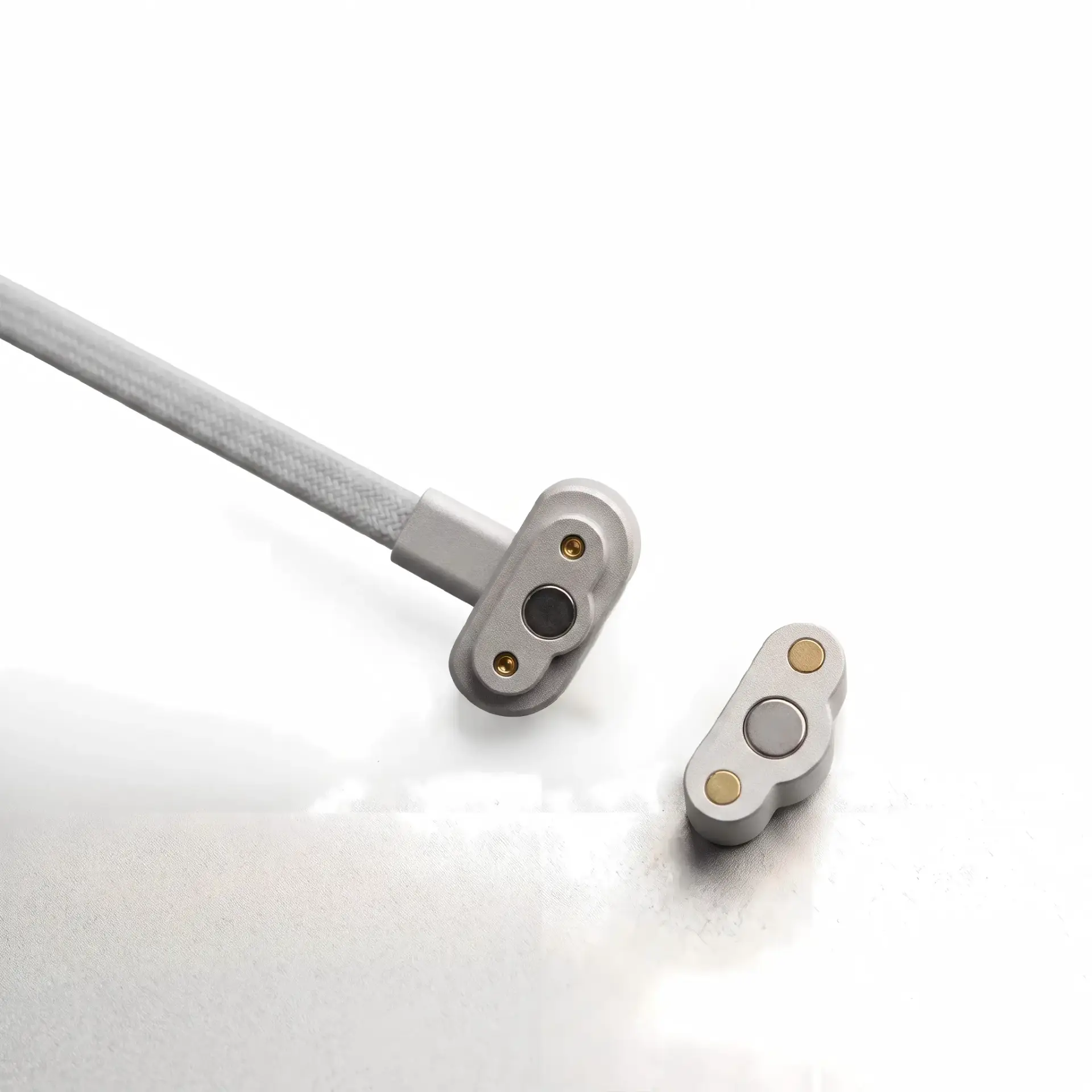
Gold Plating does not ensure Corrosion-Free Operation
Corrosion and resistance stability also depend on:
- Underplate continuity
- Surface porosity
- Wear through the contact finish
- Contact pressure
- Mating-pad finish
- Residue trapped between contacts
- Dissimilar adjacent metals
- Electrical bias while moisture is present
- Cleaning and drying procedures
The article should therefore avoid claims such as:
- Absolute corrosion resistance
- Zero oxidation
- Permanent protection
- stable conductivity
Step 10: Control Pad Spacing and Offset-Mating Risk
Exposed charging pads should be reviewed under every possible connector position, not only the correct position.
Check whether an offset or rotated cable head could cause:
- Positive power contacting ground
- Power contacting a detection pad
- Two contacts bridging one device pad
- Metal housing touching an energized contact
- Moisture bridging adjacent contacts
Risk-control methods may include:
- Asymmetric contact arrangement
- Mechanical keying
- Recessed power pads
- Insulating barriers
- Controlled magnet polarity
- Dock-detection circuitry
- Current limiting
- Delayed charging enable
No single method should automatically be described as completely eliminating incorrect mating.
Step 11: Separate Magnetic Attraction from Final Alignment
Magnets can attract the cable or dock toward the device, but the housing should control the final position.
Final alignment depends on:
- Housing shape
- Locating surfaces
- Magnet position
- Magnet polarity
- Mechanical stop
- Surface flatness
- Pogo pin spring force
- Cosmetic residue or particles on the mating surface
The design should distinguish:
- Capture: The initial magnetic attraction
- Location: The final controlled connector position
- Compression: The working stroke of the pogo pins
- Retention: The force maintaining the connected condition
- Release: The force and direction required to remove the charger
a project-specified magnet grade Is Not a Universal Beauty-Device Magnet Requirement
Magnet selection depends on:
- Connector dimensions
- Magnet geometry
- Air gap
- Housing thickness
- Steel return structure
- Required holding direction
- User removal force
- Operating temperature
- Magnet coating and retention
A stronger magnet may make the charger harder to remove, increase mating impact or place excessive load on the enclosure. The objective is controlled docking rather than the maximum available magnetic force.
Step 12: Define the Pogo Pin Working Stroke
The final pogo pin compression is determined by the complete dimensional stack:
- Pogo pin free height
- Cable-head housing height
- Device-pad position
- Device-enclosure flatness
- Mechanical-stop position
- Adhesive or overmolding thickness
- Seal compression
- Housing deformation after magnetic engagement
| Stroke Condition | Possible Risk | Required Review |
|---|---|---|
| Minimum compression | Unstable charging or detection | Minimum force and dynamic continuity |
| Nominal compression | Primary operating condition | Resistance, force and temperature rise |
| Maximum compression | Wear, pad loading or mechanical bottoming | Over-travel and enclosure load |
| Uneven compression | One power contact carries more current | Housing flatness and pin-by-pin comparison |
Step 13: Design the Cable for the Actual User
The cable should be reviewed together with the handheld device.
Define:
- Cable length
- Cable flexibility
- Conductor size
- Cable exit angle
- Strain-relief stiffness
- Connector-head dimensions
- Charging orientation
- Whether the device rests on a surface while charging
- Whether the cable pulls the device over
A compact charging head can still produce a poor user experience when the cable is too stiff or exits in the wrong direction.
Breakaway Behavior Should Be Defined by Direction
A magnetic charging cable may separate when pulled, but axial, lateral and peel forces can be different.
Evaluate:
- Normal user removal
- Cable pulled across a table
- Device lifted while charging
- Cable caught by another object
- Device dropped from a charging position
The breakaway requirement should protect the device without causing normal charging interruptions.
Step 14: Consider a Charging Dock Instead of a Loose Cable
A dock may be useful when the product requires:
- A defined storage position
- Repeatable alignment
- One-handed placement
- Cable-load isolation
- Air circulation around the device
- A controlled drying orientation
The dock should be reviewed for:
- Base stability
- Drainage
- Contact accessibility
- Cleaning
- Device center of gravity
- Charging heat
- Cable exit direction
- Incorrect placement
A recessed dock can improve alignment but may also trap liquid or cosmetic residue if drainage is not considered.
Step 15: Validate the Complete Device Assembly
Connector-level testing is useful during development, but final approval should represent the complete device, including:
- Production-intent enclosure
- Production-intent contact insert
- PCB and charging circuit
- Final cable or dock
- Seals and adhesives
- Cosmetic finishes
- Production assembly process
Beauty-Device Charging Interface Validation Matrix
| Requirement | Possible Evaluation | Example Output |
|---|---|---|
| Charging power | Complete-path voltage-drop and temperature-rise test | Voltage, current, resistance and stabilized temperature |
| Correct docking | Alignment, detection and offset-mating evaluation | Valid and invalid mating positions |
| Contact stability | Resistance measurement at minimum, nominal and maximum stroke | Individual channel resistance |
| Wet-state behavior | Project-specific moisture and abnormal-condition assessment | Charging enable, current limiting and fault response |
| Enclosure protection | Ingress test on the final assembled device | Tested state, configuration and result |
| Humidity and condensation | Cyclic damp-heat conditioning where applicable | Post-test function, insulation and appearance |
| Cosmetic residue | Exposure to defined gel, serum, oil or cleaning product | Resistance, material condition and cleanability |
| Repeated cleaning | Project-defined cleaning cycles | Housing, printing, finish and seal condition |
| Magnetic usability | Capture, holding and separation-force measurements | Force-displacement behavior in defined directions |
| Cable durability | Flexing, pull and strain-relief evaluation | Continuity and physical condition |
| Repeated docking | Application-defined mating operation test | Resistance, force, pad wear and appearance change |
Define Acceptance Criteria Before Testing
A test plan should define:
- Maximum permitted contact resistance
- Maximum permitted resistance change
- Maximum temperature rise
- Minimum and maximum charging force
- Permitted cosmetic or surface change
- Permitted pad wear
- Post-cleaning functional requirements
- Ingress-test configuration
- Wet-state charging behavior
- Failure and retest rules
Statements such as “passed waterproof testing” or “passed cosmetic testing” are incomplete without the tested product, substance, duration, state and acceptance criteria.
Common Beauty-Device Connector Design Mistakes
| Design Mistake | Possible Consequence | Better Engineering Approach |
|---|---|---|
| Assuming IP68 applies to the cable itself | The final device or unmated state may not be protected | Define and test the complete enclosure configuration |
| Allowing charging immediately after rinsing without review | Moisture may bridge or contaminate exposed contacts | Define drying, detection and charging-enable behavior |
| Using a deep decorative recess | Gel, oil and water can accumulate around the contacts | Design an accessible surface with drainage and wipe access |
| Choosing Pin count before defining functions | Unnecessary contacts increase complexity | Define power, detection and communication requirements first |
| Specifying a universal gold thickness | The finish may not match the force, pad or environment | Approve the complete contact and plating system |
| Using stronger magnets as the only alignment method | Removal force and mating impact may increase | Use housing guidance and a controlled mechanical stop |
| Testing only with water | Actual gels, oils or cleaning chemicals remain untested | Use defined field substances and cleaning procedures |
| Testing the connector outside the device | Enclosure sealing, PCB movement and charging logic are missed | Validate the final device, cable and charging circuit |
| Describing exposed contacts as 100% safe | Product-level electrical and abnormal conditions remain undefined | Confirm safety through the complete device design and applicable standards |
| Promising samples promised before engineering review before requirements are frozen | The sample may not represent the final electrical or sealing design | Confirm Pin Map, dimensions, materials and validation scope first |
Applicable Standards Depend on the Beauty-Device Category
The following standards may support the engineering review. Their applicability and required editions should be confirmed for the specific product and target market.
- IEC 60529: Classification of degrees of protection provided by electrical enclosures
- IEC 60068-2-30:2025: Cyclic damp-heat testing with temperature changes and generally occurring condensation
- IEC 60512-2-2: Contact-resistance measurement using a specified test current
- IEC 60512-13-1: Measurement of connector engaging and separating forces
- IEC 60335-1: General safety requirements for household and similar electrical appliances
- IEC 60335-2-115: Particular requirements for applicable skin beauty-care appliances
- IEC 60335-2-113: Particular requirements for applicable beauty-care appliances using lasers or intense light sources
A connector test report does not replace the applicable finished-product safety assessment.
Information Required for a Custom Beauty-Device Charging Interface
Prepare the following information before requesting a custom magnetic charging cable or dock:
- Beauty-device type and treatment function
- Use environment
- Cleaning method
- Expected cosmetic, gel, oil or chemical exposure
- Charging input voltage and current
- Battery and charging-management requirements
- Required Pin Map
- Whether docking detection is required
- Whether charging is permitted after rinsing or while moisture is present
- Available connector dimensions
- Device-side PCB and enclosure drawings
- Mating and removal directions
- Required holding and breakaway forces
- Working-stroke and tolerance requirements
- Required ingress-protection state
- Cable length and termination
- Expected mating and cleaning frequency
- Applicable product standards
- Required prototype and validation documents
Frequently Asked Questions
Are magnetic charging cables automatically waterproof?
No. Ingress protection depends on the complete device enclosure, contact insert, seals, cable entry, adhesive, manufacturing process and tested mating state.
Can a beauty device be charged immediately after washing?
That depends on the finished device design and approved use instructions. The engineering team should define drying requirements, exposed-contact state, charging detection and abnormal-condition protection.
Should the beauty device use pogo pins or flat contact pads?
Both arrangements are possible. Flat pads on the device may be easier to wipe, while pogo pins can provide compliance. The selection depends on exposure, enclosure structure, serviceability and cleaning requirements.
How many contacts does a beauty-device charger need?
A simple design may require only power and ground. Additional contacts may support docking detection, identification, temperature sensing or communication. The Pin Map should be based on actual functions.
Does thicker gold plating supports better corrosion resistance?
No. Performance also depends on the base material, underplate, porosity, contact force, mating pad, wear, residue and environmental exposure.
Can salt-mist testing prove compatibility with skincare products?
No. Salt mist and cosmetic chemical exposure represent different conditions. Actual gels, oils, lotions and cleaning agents should be defined and evaluated separately where relevant.
Does a stronger magnet improve charging reliability?
Not automatically. Excessive attraction may increase mating impact, removal force, housing load or pogo pin compression. Housing guidance and working stroke are also important.
Should the charging contacts remain energized when disconnected?
The appropriate electrical state depends on the charging architecture and safety assessment. Detection, current limiting or controlled power enable may be considered where exposed contacts create an application risk.
Why does a charging interface work when clean but fail after normal use?
Cosmetic residue, condensation, incomplete drying, contact wear, reduced working stroke or contamination around the magnets may alter electrical and mechanical behavior.
Can the magnetic connector alone receive an IP68 certificate?
An individual component can be evaluated under a defined fixture or assembly, but the result does not automatically establish the IP rating of the finished beauty device. The claimed configuration must be clearly identified.
Prepare Your Beauty-Device Charging Project
Begin by defining the complete product workflow: how the device is used, what substances contact it, how it is cleaned, when it is considered dry and how charging is enabled.
Review available custom magnetic cable assemblies, access the connector engineering guides, or submit the Pin Map, enclosure drawings, charging requirements and cleaning conditions through the Get Quote & Samples page.
CTP can review the proposed Pin Map, charging path, pogo pin working stroke, magnetic structure, contact-pad layout, cable construction and enclosure interface before prototype development. Final IP ratings, chemical compatibility, charging limits and safety requirements should be confirmed through project-specific device validation.
CTP ENGINEERING PATHS
Choose the right path for your project
Move from application requirements to a connector pair, a data-capable cable assembly, or a charging cable configuration. Final specifications are confirmed against an approved drawing and project validation plan.
Magnetic Connectors
Connector geometry, pin layout, mechanical integration and OEM/ODM review.
Engineering overview → 02Magnetic Data Cables
Power and signal allocation, cable exit, interface selection and assembly review.
Cable engineering → 03Magnetic Charging Cables
Browse the complete cable catalog and shortlist a starting structure for customization.
View cable catalog →