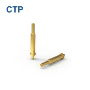
Hidden magnetic pogo pin interfaces can support modular smart-home devices
by combining spring-loaded electrical contacts with magnet-assisted
attachment inside furniture, lighting, wall-mounted accessories and other
architectural electronics. However, “hidden” or “cable-free” does not mean
wireless power or automatically safe exposed contacts. Engineers must
define the low-voltage power architecture, Pin Map, module detection,
power gating, pogo pin working stroke, mechanical datums, accessible
contact conditions and service requirements for the complete installation.
The Real Goal Is Not to Remove Every Cable
Smart-home products increasingly compete with the architectural surfaces
around them.
Sensors, lighting modules, control panels, charging accessories and other
electronic devices may need electrical power while industrial designers
want walls, desks, cabinets and ceilings to remain visually clean.
A hidden magnetic pogo pin interface can help move the visible connection
point into the product architecture.
The cable may still exist behind a wall panel, inside furniture or within a
low-voltage distribution track. What changes is the user-facing interface.
Therefore:
Cable-free at the user interface does not necessarily mean wireless
power or a cable-free electrical system.
What Is a Hidden Magnetic Pogo Pin Interface?
A hidden magnetic pogo pin interface uses spring-loaded conductive contacts
combined with a magnetic or mechanically guided mating structure so that a
removable electronic module can connect to a host surface with minimal
visible connector hardware.
The system may contain:
- A host-side power and control circuit
- Spring-loaded pogo pin contacts
- Flat mating targets
- Magnetic capture elements
- Mechanical locating features
- A removable smart-home module
The pogo pins provide electrical conduction.

The magnets provide capture or retention.

These are different engineering functions and should be designed
separately.
“Hidden” Does Not Mean the Contacts Can Sit Behind Any Decorative Surface
A conductive pogo pin interface still requires direct electrical contact
with a compatible mating target.

A normal insulating decorative layer such as wood veneer, plastic laminate
or paint cannot simply remain between the pogo pin and target while
maintaining conductive contact.
Several architectural approaches are possible:
- Expose only a small flush contact zone
- Integrate conductive target pads into the finished surface
- Place the connector inside a shallow recessed interface
- Hide the connector behind a removable architectural cover
- Integrate the complete mating interface into a track or furniture system
The final appearance therefore depends on both the electrical connector and
the industrial design of the surrounding surface.
Low-Voltage Architecture Should Be Defined Before the Connector
Hidden smart-home interfaces are more practical when the electrical
architecture has already defined what power crosses the removable
connection.

The project should identify:- Nominal supply voltage
- Maximum continuous current
- Peak or inrush current
- Power-return architecture
- Maximum permitted voltage drop
- Short-circuit protection
- Accessible-contact requirements
- Required electrical isolation
- Power-enable logic
A connector supplier should not assume that every low-voltage smart-home
bus uses the same electrical limits or safety architecture.
Low Voltage Does Not Automatically Mean Touch-Safe
Reducing voltage can simplify some aspects of exposed-contact design, but
voltage alone does not establish complete user safety.
Risk also depends on:
- Available current
- Available energy
- Short-circuit protection
- Contact spacing
- Accessible metal
- Moisture or contamination
- Foreign conductive objects
- The applicable installation and product requirements
The complete smart-home module and power system should therefore define the
safe state of the exposed interface.
Power Gating Can Keep the Interface De-Energized Until a Valid Module Is Detected
One useful architecture for an accessible magnetic interface is to separate
physical attachment from electrical power enable.
A possible system sequence is:
    Module Approaches
    →
    Magnetic Capture
    →
    Mechanical Seating
    →
    Module Detection
    →
    Compatibility Check
    →
    Power Enable
    →
    Normal Operation


The specific implementation may use a dedicated detection contact,
resistor-coded identification, a mechanical sensor or another
project-specific method.

The important distinction is:


    Magnetic attachment does not automatically mean that the power contacts
    should become energized.
Magnets Do Not Identify a Compatible Device by Themselves
A magnetic field can attract or orient a mating module, but it does not
inherently prove that the attached product is electrically compatible.
Compatibility control may require:
- Mechanical keying
- Asymmetric connector geometry
- Controlled magnet polarity
- Dedicated identification contacts
- Resistor coding
- Electronic identification
- Host-side validation before power enable
Magnetic polarity may contribute to orientation control, but it should not
automatically be treated as a complete electrical compatibility system.
Build the Pin Map Around the Module Function
A hidden smart-home interface may require more than positive and negative
power contacts.
Project-specific contact functions may include:
- Power
- Power return
- Module detection
- Accessory identification
- Power-enable control
- Dimming or actuator control
- Low-speed project-specific communication
- Service or diagnostic contacts
The correct number of pogo pins should therefore be determined from the
Pin Map rather than selecting a connector by pin count first.
Example Smart-Home Module Architectures
| Module Type | Possible Interface Functions | Primary Engineering Focus |
|---|---|---|
| Modular Light | Power, return, detection and control | Thermal design, module seating and power enable |
| Furniture Sensor | Power, return, identification and signal | Compact mounting and serviceability |
| Control Panel | Power, detection and project-specific communication | User removal, Pin Map and alignment |
| Charging Accessory | Power and detection | Current path, exposed contacts and thermal behaviour |
| Motorized Furniture Module | Power, return, enable and status | Inrush current and safe disconnection |
| Environmental Sensor Node | Power, identification and data | Low-power operation and module replacement |
These are system examples rather than fixed connector configurations.Magnetic Capture and Final Mechanical Position Are Different
Magnets can make a hidden interface easier to locate and attach, but they
should not be the only feature controlling final pogo pin position.| Mating Function | Recommended Design Control |
|---|---|
| Initial Capture | Magnet arrangement |
| Orientation | Housing geometry and mechanical coding |
| Final Position | Mechanical datum surfaces |
| Pogo Pin Compression | Mechanical stop and tolerance stack |
| Module Retention | Magnetic structure and host housing |
Flush Mounting Still Requires a Defined Working Stroke
A visually flush smart-home module can still require internal movement
inside the electrical contact.

Each pogo pin should operate within its approved working-compression range
after the module reaches the final seated position.
A simplified relationship is:
S = Hfree - Hseatedwhere:
- S is actual pogo pin compression
- Hfree is the installed free contact height
- Hseated is the final target distance
The tolerance stack may include:
- Pogo pin free-height tolerance
- Target height
- Decorative surface thickness
- Housing dimensions
- Furniture or wall-panel tolerance
- PCB position
- Mechanical-stop position
| Stroke Condition | Possible Result |
|---|---|
| Insufficient Compression | Intermittent contact or unstable resistance |
| Approved Working Stroke | Intended electrical contact condition |
| Excessive Compression | Spring bottoming, target wear or structural stress |
Furniture Movement Makes Mechanical Tolerance Important
Furniture and architectural panels are not always as dimensionally stable
as a rigid electronics enclosure.

Depending on material and construction, the interface may experience:- Panel deflection
- Assembly tolerance
- Repeated module loading
- Wood or polymer dimensional changes
- Mounting-hardware movement
- User-applied side loads
The mechanical design should ensure these changes do not push the pogo pins
outside their intended working range.
Surface Materials Must Be Part of the Connector Design
Integrating a connector into furniture or architectural surfaces introduces
material issues that may not exist in conventional electronics.
The surrounding interface may use:
- Wood
- Decorative laminate
- Metal
- Glass
- Plastic
- Painted surfaces
- Composite panels
The selected material can affect connector mounting, dimensional tolerance,
thermal behaviour, wear and visual integration.

If the surrounding surface is conductive, electrical isolation and the
intended grounding architecture should also be reviewed.
A Low-Profile Interface Is Still a Three-Dimensional Packaging Problem
A flush user-facing surface does not mean the connector requires zero
installation depth.
The hidden Z-axis stack may still include:
- Pogo pin body
- Recommended working stroke
- PCB
- Termination
- Magnet structure
- Housing
- Mechanical stop
- Backing structure
The correct design should therefore be evaluated using the complete
installation envelope rather than only the visible connector height.
Current Capability Is a Complete-Path Thermal Problem
A hidden magnetic connector may be compact, but current still flows through
the complete electrical system.
A simplified path may be:
    Power Supply
    →
    Host Wiring / PCB
    →
    Pogo Pin
    →
    Contact Interface
    →
    Mating Target
    →
    Module PCB
    →
    Load
The voltage drop is:
Vdrop = I × RpathThe resistive loss is:
Ploss = I² × Rpath

Current capability should be confirmed through complete-path voltage-drop
and temperature-rise testing.
Hidden Interfaces Need Foreign-Object Protection
A connector integrated into a desk, wall panel or furniture surface may be
accessible when no module is attached.
Possible foreign objects can include:
- Metal tools
- Keys
- Coins
- Metallic debris
- Cleaning liquids
- Other conductive household objects
Depending on the electrical architecture, protection can include current
limiting, power gating, recessed contacts, spacing, covers or
project-specific detection logic.
Magnetic Debris Can Be a Different Failure Mode
Because magnets are located near the interface, ferromagnetic debris can
be attracted toward the contact area.

This is particularly relevant for interfaces located on work surfaces or
near metal fabrication, tools or furniture hardware.
Validation may include:
- Metal-particle attraction
- Conductive bridging between contacts
- Cleaning access
- Effect on final module seating
- Electrical response to an invalid connection state
Module Removal Should Have a Defined Electrical State
A removable smart-home module may disconnect while power is present.

The project should therefore define what happens as contacts separate.
Possible considerations include:
- Power-disable sequence
- Stored energy
- Load current during separation
- Contact arcing
- Controller reset
- Module-presence detection
A magnetic breakaway interface does not automatically make energized
disconnection safe.
DALI Is a System Protocol, Not a Pogo Pin Feature
A connector can provide conductive paths used by a project-specific
lighting control architecture.

However, the presence of additional pogo pin contacts does not
automatically establish DALI or another lighting communication protocol.

Protocol capability depends on the controller, transceiver, power
architecture, PCB routing and complete electrical implementation.
Matter Is Not a Physical Connector Protocol
Matter defines interoperability at the smart-home application and network
level. A magnetic pogo pin connector does not become “Matter compatible”
simply because a device physically docks to a host.

A physical interface may be used by the product for power, accessory
identification or project-specific communication while Matter-related
commissioning and network functions are handled elsewhere in the device
architecture.

Physical docking and network commissioning should therefore be treated as
separate engineering layers.
Do Not Assume Physical Docking Should Transfer Network Credentials
A removable module can use conductive contacts for project-specific
communication, but automatic credential transfer introduces additional
system and security requirements.

The connector itself does not authenticate devices, encrypt information or
manage smart-home credentials.

Those functions belong to the host electronics, firmware and network
architecture.
Serviceability Is One of the Strongest Benefits of a Hidden Modular Interface
The value of a hidden connector is not only visual.

A modular architecture can allow selected smart-home functions to be
replaced or upgraded without permanently rewiring the complete
installation.
Possible benefits include:
- Replaceable sensor modules
- Replaceable lighting modules
- Upgradable control interfaces
- Service access without disconnecting internal wiring
- Multiple compatible accessories using one host interface
These benefits depend on the complete mechanical, electrical and software
ecosystem rather than the connector alone.
Design the Host Interface for an Empty State
Modular interfaces spend part of their life with no accessory attached.

The empty state should therefore be considered a normal product condition.| Empty-State Question | Engineering Consideration |
|---|---|
| Are Contacts Energized? | Define power-gating strategy |
| Are Contacts Accessible? | Review touch and foreign-object conditions |
| Can Dust Accumulate? | Review geometry and cleaning access |
| Can Metal Debris Be Attracted? | Review magnetic layout and electrical protection |
| Is the Surface Visually Acceptable? | Integrate connector geometry with the product finish |
Possible Hidden Magnetic Interface Applications
| Application | Possible Connector Role | Primary Engineering Focus |
|---|---|---|
| Modular Smart Lighting | Power, detection and project-specific control | Thermal design and safe module replacement |
| Smart Furniture | Power and removable accessory interface | Panel tolerance and serviceability |
| Wall-Mounted Sensor Modules | Power, ID and signal connection | Flush mounting and accessible-contact design |
| Bedside / Headboard Electronics | Accessory power and removable controls | User interaction and foreign-object protection |
| Cabinet Lighting Modules | Power and detection interface | Low-profile mounting and heat |
| Architectural Control Panels | Power and project-specific communication | Mechanical datum and replacement workflow |
These are architectural examples rather than universal recommendations.
Final suitability depends on the electrical, mechanical and regulatory
requirements of the complete installation.
Hidden Smart-Home Connector Selection Parameters
| Parameter | Engineering Definition |
|---|---|
| Pin Count | Number of required independent electrical paths |
| Pin Map | Power, return, detection, control and signal allocation |
| Available Z-Axis Space | Maximum installation depth behind the finished surface |
| Visible Surface Area | Maximum allowable exposed interface footprint |
| Working Stroke | Minimum, nominal and maximum pogo pin compression |
| Contact Force | Specify at the intended working stroke |
| Mating Target | Define dimensions, finish, flatness and integration into the module |
| Module Detection | Define how the host identifies a valid attached module |
| Power Gating | Define when accessible power contacts become energized |
| Continuous Current | Confirm through voltage-drop and temperature-rise testing |
| Magnetic Capture | Evaluate separately from final mechanical location |
| Seated Retention | Define based on module mass and user interaction |
| Surface Material | Wood, metal, glass, plastic, laminate or project-specific structure |
Recommended Validation Plan
| Requirement | Recommended Evaluation |
|---|---|
| Pin Map | Confirm the function and fault state of every contact |
| Working Stroke | Verify compression across full architectural tolerance stack |
| Flush Alignment | Verify the final visible module position |
| Module Detection | Test compatible, incompatible and partially seated modules |
| Power Gating | Verify power state with module attached and removed |
| Foreign Object | Evaluate representative conductive household objects |
| Metallic Debris | Evaluate attraction and contact-bridging conditions |
| Voltage Drop | Measure complete power path under intended load |
| Temperature Rise | Evaluate connector, wiring, PCB and surrounding materials |
| Removal Under Load | Evaluate electrical state as the module separates |
| Repeated Mating | Monitor contact and surface behaviour over defined cycles |
| Surface Wear | Inspect visible architectural finish after repeated use |
| Cleaning | Evaluate normal household cleaning and material compatibility |
Information Required for Engineering Review
| Project Input | Information to Provide |
|---|---|
| Application | Lighting, furniture, wall sensor, control panel or another smart-home module |
| Pin Map | Function of every required electrical contact |
| Electrical Conditions | Voltage, continuous current and peak current |
| Detection Requirement | How the host should recognize a valid module |
| Power State | Whether the host contacts remain energized when no module is attached |
| Surface Material | Wood, metal, glass, laminate, plastic or other finish |
| Available Space | Maximum visible footprint and hidden installation depth |
| Working Stroke | Minimum, nominal and maximum pogo pin compression |
| Mating Direction | Approach, final seating and removal direction |
| Retention Requirement | Module mass, user pull direction and required release behaviour |
| Communication | Any project-specific control or data requirements |
| Project Files | 2D drawing, 3D model, PCB layout or furniture / architectural assembly |
Frequently Asked Questions
What are hidden magnetic pogo pins for smart homes?
They are spring-loaded electrical contact interfaces integrated into
furniture, lighting, wall-mounted devices or other architectural hardware
where the visible connector is minimized and magnets assist removable
module attachment.
Does cable-free mean wireless power?
No. A pogo pin interface still transfers power through conductive physical
contacts. Cabling or PCB traces may simply be hidden inside the furniture,
wall, track or host structure.
Can pogo pins conduct through wood or decorative laminate?
Not through a normal insulating layer. The pogo pin must physically reach
a conductive mating target or an intentionally integrated conductive
interface.
Are low-voltage exposed contacts automatically safe?
No. Safety depends on voltage, available current and energy, short-circuit
protection, accessibility, moisture, foreign objects and the requirements
applicable to the complete product or installation.
Can magnets automatically turn the power on?
Not by themselves. A project can use module detection and electronic power
control so that power is enabled after a valid mating state is recognized.
Can hidden magnetic pogo pins support smart lighting?
They can provide project-specific power and control contact paths for
removable lighting modules, but the electrical load, thermal design,
control architecture and safety requirements must be validated for the
complete system.
Does a magnetic pogo pin interface automatically support DALI?
No. The connector only provides conductive paths. DALI capability depends
on the complete lighting controller, transceiver and system architecture.
Does a pogo pin connector automatically support Matter?
No. Matter operates at the smart-home networking and application layer.
The connector can provide physical power or project-specific electrical
communication, but it does not establish Matter compatibility by itself.
Can the interface transfer network credentials automatically?
Only if the complete product electronics and software are intentionally
designed for that function. The connector itself does not authenticate,
encrypt or provision network credentials.
What information is needed for a hidden smart-home connector?
Provide the Pin Map, voltage, current, host surface material, available
visible and hidden space, working stroke, module detection strategy,
power-gating requirement, mating direction and available product drawings.
Request a Hidden Smart-Home Interface Engineering Review
Explore

    custom magnetic connector solutions

for different pin counts, compact layouts and removable module structures.

Learn more about CTP engineering and manufacturing capabilities on our

    About Us page
.

Submit the Pin Map, electrical requirements, surface structure, available
installation space and project drawings through the

    Get Quote & Samples page
.


    CTP can review the contact layout, pogo pin working stroke, mating
    targets, magnetic capture structure, module detection concept and PCB,
    FPC or wire termination for custom smart-home and architectural
    electronic interfaces. Final electrical safety, protocol compatibility,
    thermal performance, user accessibility and installation compliance
    depend on the complete customer product and project-specific validation.
CTP ENGINEERING PATHS
Choose the right path for your project
Move from application requirements to a connector pair, a data-capable cable assembly, or a charging cable configuration. Final specifications are confirmed against an approved drawing and project validation plan.
Magnetic Connectors
Connector geometry, pin layout, mechanical integration and OEM/ODM review.
Engineering overview → 02Magnetic Data Cables
Power and signal allocation, cable exit, interface selection and assembly review.
Cable engineering → 03Magnetic Charging Cables
Browse the complete cable catalog and shortlist a starting structure for customization.
View cable catalog →