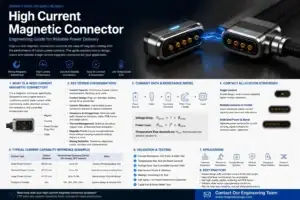
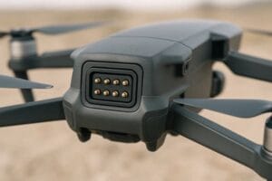
High-current magnetic pogo pin interfaces can support automated EV charging,
controlled fleet docking, battery-swap equipment and selected service
connections. Their practical current capability is determined by the complete
electrical and thermal path rather than contact diameter alone. Engineers
should evaluate parallel-contact current sharing, working stroke, contact
resistance, temperature rise, thermal-sensor placement, mating sequence,
contamination and fault response as one charging-system problem.
Where High-Current Magnetic Pogo Pins Fit in EV Charging
EV charging includes several different electrical interfaces, and they
should not all be treated as the same connector problem.
Magnetic pogo pin interfaces are generally easier to evaluate in
controlled docking environments where mating position, charging sequence,
maintenance and environmental exposure can be managed by the complete
system.| Interface | Possible Role | Primary Engineering Focus |
|---|---|---|
| Automated Vehicle Dock | Automatic charging connection between vehicle and station | Alignment, current path, sequencing and thermal monitoring |
| Battery-Swap System | Repeated electrical connection between removable battery and host | Current sharing, retention, endurance and interlock |
| Fleet Charging Equipment | Controlled charging for vehicles operating in a defined depot | Repeatability, contamination, maintenance and fault detection |
| Auxiliary EV Interface | Low-voltage charging, service or diagnostic connection | Voltage drop, accessibility and environmental protection |
| Public Fast-Charging Interface | Standardized traction-battery charging connection | Standardized coupling, locking, insulation, communication and certification |
A magnetic pogo pin array should therefore not be positioned as a universal
replacement for standardized public charging couplers.
High Current Is Primarily a Thermal Problem
A pogo pin can conduct current while still operating outside an acceptable
thermal condition.

For EV charging, the useful engineering question is not simply:

“How many amperes can this pogo pin carry?”

A better question is:


    “At the required current, working stroke, ambient temperature and
    duty cycle, what temperature does the complete charging path reach?”


The connector should therefore be evaluated as part of the complete
resistance and thermal network.
Build the Complete Charging Resistance Path
A simplified high-current path may include:
    Charger Output
    →
    Cable / Busbar
    →
    Connector Termination
    →
    Pogo Pin
    →
    Contact Interface
    →
    Mating Target
    →
    Vehicle Busbar / PCB
    →
    Vehicle Charging Electronics
The total resistance can be represented as:
    Rpath =
    Rcable +
    Rtermination +
    Rpogo +
    Rinterface +
    Rtarget +
    Rvehicle
The resulting voltage drop is:
Vdrop = I × RpathResistive power loss is:
Ploss = I² × Rpath

This squared-current relationship is one reason small resistance increases
become increasingly important as charging current rises.
Low Pogo Pin Resistance does not ensure a Low-Resistance Charging System
The pogo pin is only one part of the conductive path.

A low-resistance spring contact cannot compensate for:- undersized cables;
- narrow busbars;
- poor welds or crimps;
- high-resistance PCB transitions;
- contaminated mating targets;
- unequal current paths;
- poor thermal interfaces.
Voltage-drop and temperature-rise testing should therefore include the
complete assembled charging path.
Parallel Pogo Pins Do Not Automatically Share Current Equally
High-current charging interfaces may place several pogo pins in parallel
for the positive and return paths.

Increasing the number of contacts increases available conductive area, but
it does not ensure equal current distribution.
Current sharing can be affected by:
- working-stroke differences;
- installed-height variation;
- contact-resistance variation;
- target flatness;
- connector tilt;
- busbar routing length;
- termination resistance;
- surface contamination;
- local temperature.
Why Current Imbalance Matters
Consider a charging interface with several nominally identical parallel
contacts.

If one branch has lower electrical resistance, it can carry a larger share
of the total charging current.

That contact can then experience higher local heating.

If another contact subsequently degrades or becomes open, the remaining
contacts must carry additional current.| Condition | Possible Effect | Recommended Evaluation |
|---|---|---|
| Unequal Working Stroke | Different interface resistance | Measure compression and branch current |
| Unequal Busbar Length | Current concentrates in the lower-resistance branch | Measure branch resistance and temperature |
| One Contact Becomes Open | Remaining contacts receive additional load | Run degraded-contact fault testing |
| One Target Is Contaminated | Current distribution changes across the array | Test representative contamination states |
Design Parallel Power Paths Symmetrically
Useful controls include:
- similar conductor lengths for parallel branches;
- similar pogo pin working stroke;
- controlled target flatness;
- symmetrical busbar or PCB geometry;
- balanced termination structures;
- branch-current measurement during validation;
- temperature measurement around individual contact groups.
The current rating of a parallel array should not simply be calculated by
multiplying the rating of one contact by the number of contacts.
Working Stroke Influences Electrical and Thermal Performance
Each pogo pin should operate inside its approved compression range after
the charging interface reaches its final seated position.
A simplified relationship is:
S = Hfree - Hseatedwhere:
- S is the actual working compression;
- Hfree is the installed free height;
- Hseated is the final seated contact height.
| Stroke Condition | Possible Result |
|---|---|
| Too Little Compression | Higher or unstable contact resistance |
| Approved Working Stroke | Intended contact-force and electrical condition |
| Excessive Compression | Spring bottoming, target wear or excessive structural load |
| Unequal Compression Across the Array | Current-sharing imbalance |
Temperature Rise Defines the Practical Charging Limit
A useful current limit should be based on a defined thermal condition,
not only on short-duration electrical continuity.
Temperature-rise testing should consider:
- continuous charging current;
- peak current and duration;
- charging duty cycle;
- maximum required ambient temperature;
- minimum acceptable working stroke;
- actual cable or busbar system;
- final connector housing;
- contacts after repeated mating;
- representative contamination;
- degraded-contact conditions.
Measure the Real Hot Spots
A connector-temperature measurement is meaningful only when the measurement
locations represent the parts of the system likely to overheat.
Useful measurement locations may include:
- pogo pin interface;
- mating target;
- pogo pin termination;
- cable or busbar joint;
- vehicle-side conductor transition;
- connector housing;
- embedded temperature sensor locations.
A housing temperature can remain acceptable while a localized contact or
termination is significantly hotter.
Temperature Sensors Must Represent the Contact Fault
Adding a temperature sensor does not automatically solve a thermal problem.The sensor system should define:
- location relative to the expected hot spot;
- thermal path from the contact to the sensor;
- sensor response time;
- housing thermal conductivity;
- potting or insulation effects;
- software filtering;
- warning threshold;
- current-derating threshold;
- shutdown strategy;
- sensor open- and short-circuit diagnostics.
Localized fault testing is particularly important because a single
high-resistance contact may heat differently from the rest of the connector.
Thermal Protection Needs a Defined Control Response
Temperature measurement is useful only when the charging controller knows
how to respond.
A possible control strategy may include:
    Normal Temperature
    →
    Full Charging Current
    →
    Elevated Temperature
    →
    Current Derating
    →
    High Temperature
    →
    Controlled Charging Shutdown
    →
    Fault / Maintenance State


Exact thresholds must be defined using the approved connector, material,
battery and charging-system requirements.
Magnetic Docking Should Not Carry the Entire Alignment Problem
Automated charging systems may arrive at the connector with lateral,
vertical and angular positioning error.

Magnets can assist final engagement, but the larger positioning error should
normally be reduced before the pogo pins contact their targets.
A controlled docking architecture may include:
- vehicle-position detection;
- mechanical guides;
- funnel or tapered locating surfaces;
- a floating connector mount;
- compliant mechanisms;
- final magnetic capture;
- mechanical stops controlling pogo pin compression.
Separate the Mechanical Load Path from the Electrical Contacts
Pogo pins should primarily provide compliant electrical contact.A preferred structural load path is:
    Vehicle / Battery Module
    →
    Dock Housing
    →
    Mechanical Stops
    →
    Charging Structure
rather than:
    Vehicle / Battery Module
    →
    Pogo Pin Plunger
    →
    Spring
    →
    PCB / Termination


This becomes particularly important in automated systems where repeated
docking can introduce impact and off-axis loads.
Partial Mating Is an Electrical Fault State
During angled or incomplete docking, individual contacts may engage at
different times.| Mating State | Possible Risk | System Requirement |
|---|---|---|
| One Power Contact Touches First | Unexpected localized energization | Main power remains disabled |
| Detection Contact Touches First | Dock reported before stable power contact | Validate full seated condition |
| Only Some Parallel Contacts Engage | High current concentration | Do not enable charging |
| Connector Is Magnetically Captured but Offset | Unstable resistance | Mechanical seating verification |
| Separation Begins Under Load | Electrical arcing | Remove current before physical separation |
Power Should Be Enabled Only After a Valid Docking State
A high-current charging interface should not normally rely on first physical
contact as the command to energize the main power path.
A possible state sequence is:
    Approach
    →
    Mechanical Seating
    →
    Connector Detection
    →
    Interlock Validation
    →
    Voltage / Pre-Charge Check
    →
    Main Contactor Closure
    →
    Controlled Current Ramp


The exact architecture is project-specific, but the principle remains:
physical mating and high-current power enable should be separate states.
A Pilot Contact Does Not Suppress an Arc
A shorter or longer detection contact can help the control system recognize
a connection state.

It does not physically eliminate an arc by itself.

Arc prevention depends on the controller and switching system removing or
reducing current before the main power contacts separate.

During undocking, the desired sequence may therefore be:


    Charging Current Reduced
    →
    Main Contactors Open
    →
    Electrical State Confirmed
    →
    Connector Released
    →
    Power Contacts Separate
Sequencing Must Be Tested Under Real Docking Error
Contact sequencing can behave differently when the connector approaches
at an angle.
Validation should include:
- straight mating;
- maximum lateral offset;
- maximum angular offset;
- slow engagement;
- fast engagement;
- partial engagement;
- one obstructed contact;
- one contaminated target.
A contact sequence that works during closely perpendicular bench testing
should not automatically be assumed to work in an automated docking system.
Contact Wear Depends on the Actual Mating Motion
Pogo pins primarily move axially, but a magnetic pogo pin interface is not
wear-free.
Wear can result from:
- lateral sliding during final alignment;
- connector tilt;
- vibration while energized;
- abrasive contamination;
- excessive working stroke;
- poor mechanical guidance;
- electrical arcing.
Magnets should assist final seating rather than drag poorly aligned live
contacts across their mating pads.
Contact Material Is Only One Part of Reliability
Contact alloy and surface finish influence conductivity, wear and corrosion
behaviour.

They cannot compensate for poor working stroke, side loading, contamination,
current imbalance or arcing.
Material selection should consider:
- continuous and peak current;
- spring requirements;
- working temperature;
- mating-cycle target;
- working stroke;
- contact force;
- tip and target geometry;
- environmental exposure;
- surface-finish compatibility.
Alloy and plating claims should be tied to the exact connector drawing and
qualification conditions.
Environmental Contamination Can Become a Thermal Fault
Outdoor or depot charging interfaces may be exposed to dust, moisture,
road residue, salts, cleaning chemicals and other contamination.

Contamination is not only an environmental issue. It can change electrical
contact resistance and therefore change temperature rise.
The complete design should evaluate:
- exposed mating pads;
- water drainage;
- housing sealing;
- condensation;
- cleaning access;
- corrosion compatibility;
- contact resistance after contamination;
- thermal behaviour after contamination exposure.
Magnets Introduce a Metallic-Debris Failure Mode
Permanent magnets can attract ferromagnetic particles toward the charging
interface.
Metallic debris can potentially:
- bridge adjacent contacts;
- prevent complete seating;
- change working stroke;
- scratch target surfaces;
- increase local resistance;
- interfere with docking detection.
Possible controls include:
- recessed power contacts;
- insulating barriers;
- accessible cleaning geometry;
- protective covers;
- pre-charge validity checks;
- current limiting;
- debris exposure during qualification.
Liquid Cooling Does Not Eliminate Contact-Resistance Limits
Active cooling may be considered when passive thermal paths cannot maintain
acceptable operating temperatures.

However, cooling the cable, busbar or connector housing does not ensure that the actual pogo pin interface remains inside its approved temperature
range.
Liquid-cooled systems also introduce:
- coolant-channel design;
- electrical isolation requirements;
- leak detection;
- hose and seal reliability;
- pressure-drop management;
- condensation control;
- service procedures;
- coolant-material compatibility.
Contact temperature and coolant temperature should therefore be measured
separately.
Define the Fault Response Before Qualification
| Fault | Possible Consequence | Possible System Response |
|---|---|---|
| One Parallel Contact Opens | Remaining contacts carry additional current | Detect abnormal temperature or voltage drop and derate current |
| Contact Resistance Increases | Localized heating | Thermal monitoring and controlled shutdown |
| Partial Mating | Incomplete power path | Keep main power disabled |
| Conductive Debris | Unintended current path | Pre-charge check, current limiting and fault lockout |
| Unexpected Separation | Arc risk | Rapid power interruption and mechanical retention strategy |
| Temperature Sensor Fault | Thermal fault may become undetected | Sensor diagnostics and conservative fallback mode |
EV Charging Magnetic Connector Validation Matrix
| Validation Area | Recommended Evaluation |
|---|---|
| Complete Resistance Path | Measure resistance from charger-side conductor to vehicle-side conductor |
| Docking Tolerance | Evaluate maximum lateral, vertical and angular misalignment |
| Working Stroke | Verify minimum, nominal and maximum compression across the array |
| Current Sharing | Measure current distribution across parallel power contacts |
| Voltage Drop | Measure the complete charging path under intended load |
| Temperature Rise | Evaluate at required current, ambient and duty cycle |
| Localized Hot Spot | Create a representative high-resistance contact fault |
| Thermal Sensor Response | Verify sensor location, response time and control-system action |
| Partial Mating | Evaluate tilted, offset and incomplete engagement |
| Power Sequencing | Verify detection, interlock, pre-charge and main-power states |
| Abnormal Separation | Verify current interruption before contact separation |
| Contamination | Evaluate dust, road residue, moisture and metallic debris |
| Repeated Docking | Monitor resistance, temperature, working stroke and surface wear |
| Single-Contact Fault | Verify current redistribution and thermal response |
Durability Claims Need Electrical Context
A connector mating-cycle number is meaningful only when the test conditions
are known.
The endurance record should define:
- connector revision;
- working stroke;
- mating speed;
- alignment condition;
- electrical load during mating and separation;
- ambient conditions;
- surface cleaning;
- measurement intervals;
- electrical and mechanical failure criteria.
A high cycle count generated in a clean and unpowered laboratory test
should not automatically be applied to a powered outdoor EV charging
interface.
When a Magnetic Pogo Pin Architecture May Not Be the Best Choice
A different charging connector architecture may be more appropriate when:
- a standardized public charging coupler is required;
- the interface needs strong positive mechanical locking;
- accessible contacts cannot reliably remain de-energized;
- environmental contamination cannot be controlled;
- required electrical spacing cannot fit the available interface area;
- contact temperature or mating state cannot be monitored;
- the required current exceeds the validated thermal capability of the proposed array;
- the project depends on an established certified connector ecosystem.
In these situations, a mechanically locked standardized connector,
dedicated busbar interface or another high-power architecture may provide
a clearer engineering path.
Information Required for an EV Charging Connector Review
| Project Input | Information Required |
|---|---|
| Interface Location | Vehicle dock, battery-swap module, charging rack or auxiliary interface |
| Charging Method | Automated or manual connection |
| Voltage | Operating and relevant transient conditions |
| Current | Continuous current, peak current and peak duration |
| Duty Cycle | Charging duration and expected recovery time |
| Voltage-Drop Limit | Maximum acceptable complete-path voltage drop |
| Thermal Limit | Maximum permitted connector and conductor temperature |
| Power Contacts | Proposed number of positive and return contacts |
| Working Stroke | Minimum, nominal and maximum compression |
| Docking Tolerance | Maximum lateral, vertical and angular misalignment |
| Power Sequence | Detection, interlock, pre-charge and contactor logic |
| Thermal Sensors | Sensor location and charging-control strategy |
| Cooling | Passive or active thermal-management method |
| Environment | Dust, moisture, metallic debris, cleaning and temperature conditions |
| Project Files | 2D drawing, 3D assembly, busbar design and electrical architecture |
Frequently Asked Questions
Can magnetic pogo pins be used for EV charging?
They can be evaluated for controlled automated charging, battery-swap,
fleet-docking and selected auxiliary interfaces. Their suitability depends
on the required voltage, current, thermal performance, mating control and
complete charging-system architecture.
Can magnetic pogo pins replace a standard public EV charging plug?
Not automatically. Standard public charging interfaces include requirements
for standardized mating, locking, safety, communication and certification
that extend beyond the electrical contact itself.
What limits the current of a pogo pin charging interface?
The practical limit is strongly influenced by complete-path resistance,
working stroke, contact force, termination, conductor geometry, ambient
temperature, cooling and permitted temperature rise.
Can several pogo pins be connected in parallel for higher current?
Yes, parallel contacts can be considered, but their currents may not divide
equally. Branch resistance, compression and temperature should be measured
under the intended charging condition.
Why does working stroke matter for high-current charging?
Working stroke affects the mechanical and electrical state of the contact.
Unequal or insufficient compression can contribute to resistance variation
and current imbalance across a parallel array.
Why should contact temperature be monitored?
A localized increase in interface resistance can generate additional heat.
Temperature sensing can provide the charging controller with information
needed for current derating or shutdown.
Can charging start as soon as the magnets connect?
Not necessarily. Magnetic capture can occur before every power contact
reaches a stable working condition. A controlled system should validate the
required docking and interlock states before enabling the main charging
path.
Does a detection pin prevent arcing?
No. A detection contact provides state information. Arc prevention depends
on the charging controller and switching devices reducing or removing
current before the main contacts separate.
Does liquid cooling allow unlimited charging current?
No. Active cooling can improve thermal management, but contact resistance,
current density, working stroke, electrical spacing, materials and fault
conditions still impose design limits.
How should EV charging connector service life be validated?
Repeatedly cycle the complete interface under defined working stroke,
alignment, electrical load and environmental conditions, then monitor
resistance, temperature, current sharing and contact-surface condition at
defined intervals.
Request an EV Charging Interface Engineering Review
Explore

    custom magnetic connector solutions

for automated docking, battery interfaces and project-specific high-current
contact structures.

Review

    pogo pin and spring-contact solutions

for custom electrical and mechanical requirements.

Submit the voltage, current, duty cycle, docking tolerance, working stroke,
proposed contact arrangement, thermal-management strategy and project
drawings through the

    Get Quote & Samples page
.


    CTP can review the contact layout, parallel-current architecture,
    pogo pin working stroke, mating targets, magnetic capture, busbar or PCB
    termination and thermal-validation requirements for custom automated
    charging interfaces. Final current capability, voltage rating,
    temperature rise, charging safety, environmental performance and
    service life depend on the complete customer charging system and
    project-specific validation.