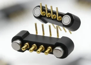
Custom magnetic USB cables can reduce repeated insertion into a device-side
receptacle by moving routine mating to a removable magnetic interface.
For OEM portable devices, however, reliability depends on the complete
architecture: device-side connector strategy, mechanical alignment,
breakaway behavior, pogo pin working stroke, Pin Map, power path, data
channel, exposed-contact protection, cable strain relief and lifecycle
validation. Magnetic attachment can change where wear occurs, but it does
not make the complete cable or connector wear-free.
Why Port Failure Is Really an Interface Architecture Problem
Portable electronics often experience repeated charging, docking and cable
handling throughout their service life.
In some products, the device-side receptacle becomes one of the interfaces
that users interact with most frequently.
Mechanical problems can come from several different sources:- repeated plug insertion and removal;
- off-axis cable loading;
- cable snagging;
- connector contamination;
- damaged cable strain relief;
- incorrect plug orientation or handling;
- wear of the removable connector itself.
A custom magnetic USB cable does not simply make these failure modes
disappear.

Instead, it can change the connection architecture so that routine user
mating occurs at a dedicated magnetic interface rather than repeatedly at
the original device receptacle.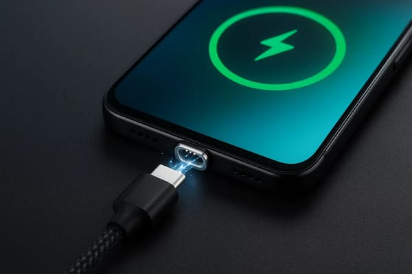
but device protection still depends on the complete mechanical and
electrical architecture.
Two Different Magnetic USB Cable Architectures
Not every custom magnetic USB cable should be designed around the same
device-side structure.

Two common architectural approaches should be distinguished.| Architecture | Device-Side Interface | Main Engineering Focus |
|---|---|---|
| Detachable Adapter Architecture | A small USB adapter remains inside an existing device receptacle | Adapter fit, port loading, contamination and accessory compatibility |
| Dedicated OEM Magnetic Interface | The product is designed with a custom magnetic target or pogo pin interface | Pin Map, working stroke, enclosure integration and system validation |
For an existing product, a detachable adapter can reduce how frequently the
original receptacle is directly inserted and removed.

For a new OEM product, a dedicated magnetic interface gives engineers more
freedom to design the enclosure, electrical functions and mechanical
behavior around the actual application.
Strategy 1: Move Repetitive Mating Away from the Original Device Port
The most direct way a magnetic USB architecture can reduce conventional
port wear is by allowing the device-side adapter or magnetic target to stay
in place while the cable connects to the magnetic interface.

This changes the daily interaction from:


    USB Plug
    →
    Device Receptacle
    →
    Remove
    →
    Reinsert
to:
    Magnetic Cable
    →
    Magnetic Interface
    →
    Separate
    →
    Reconnect


The device receptacle may therefore experience fewer direct insertion
cycles.
But Port Wear Is Reduced, Not Universally Eliminated
The adapter itself can still transfer force into the underlying USB
receptacle if it is:- hit from the side;
- used as a structural handle;
- left protruding from the device;
- loaded by an improperly designed magnetic head;
- damaged during transport.
For retrofit architectures, the geometry between the adapter and original
device receptacle therefore remains important.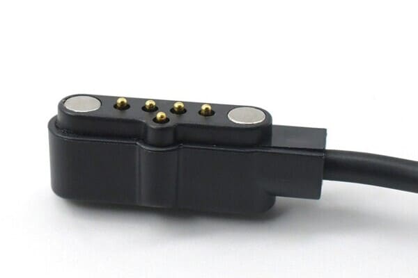
receptacle, but adapter geometry and side-load behavior should still be
evaluated.
Strategy 2: Design Magnetic Capture Around Real User Interaction
Magnetic attraction can make a cable easier to connect when visibility,
access or user dexterity is limited.

Instead of requiring the user to align and insert a plug deeply into a
receptacle, the cable can begin attracting as the two halves approach.
A simplified mating sequence is:
    Cable Approaches
    →
    Magnetic Capture
    →
    Mechanical Guidance
    →
    Final Seating
    →
    Electrical Contact


This can be useful in:- vehicle cabins;
- handheld industrial equipment;
- portable medical equipment;
- charging cradles;
- devices connected repeatedly during a work shift.
Magnetic Capture Is Not Precision Alignment
Magnets can help bring the connector halves together, but final electrical
position should normally be controlled by the connector geometry.| Function | Recommended Control |
|---|---|
| Initial Capture | Magnet arrangement |
| Orientation | Housing geometry or mechanical coding |
| Final Position | Mechanical datums / stops |
| Electrical Compliance | Pogo pin working stroke |
A magnetic snap should not be treated as proof that every electrical
contact has reached its intended condition.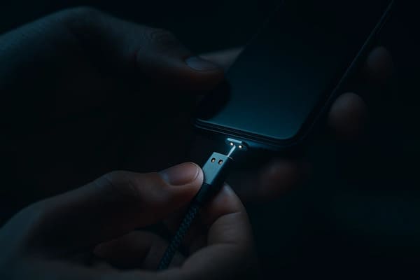
access is limited, while final alignment remains a mechanical design
requirement.
Strategy 3: Engineer Breakaway Behavior Instead of Simply Maximizing Magnetic Force
One useful characteristic of a magnetic cable is the ability to separate
without operating a rigid latch.

This can reduce the amount of cable load transferred to the device in
certain snagging conditions.

However, a cable should not simply be described as having “zero-force
breakaway.”
Actual separation behavior depends on:
- magnet arrangement;
- seated retention;
- cable exit angle;
- axial pull direction;
- peel direction;
- device mass;
- surface friction;
- connector housing geometry.
Retention and Breakaway Are Different Requirements
| Mechanical Requirement | Engineering Meaning |
|---|---|
| Capture | How the cable behaves while approaching the device |
| Seated Retention | How strongly the cable remains connected during normal use |
| Axial Separation | Force required for straight pull-off |
| Peel Separation | Behavior when the cable releases from one edge |
| Off-Axis Load | Behavior under lateral or twisting cable movement |
A cable designed to release easily when snagged should still remain stable
during normal charging and device handling.
Breakaway Does Not Eliminate the Need for Cable Strain Relief
Magnetic separation and cable strain relief address different mechanical
problems.

Breakaway behavior manages force at the removable connector interface.

Strain relief manages repeated bending and tensile loading where the cable
enters the connector body.
A cable assembly should therefore consider:
- minimum practical bend region;
- jacket-to-housing transition;
- wire anchoring;
- overmolding or strain-relief geometry;
- connector mass;
- repeated flex direction;
- pull and torsion loads.
Strategy 4: Build Product-Family Compatibility Around a Controlled Pin Map
Magnetic cable systems can be useful for product families in which several
devices share the same charging or accessory architecture.

However, “one cable for everything” is only valid when compatibility has
been deliberately engineered.
The devices should agree on requirements such as:
- connector geometry;
- magnetic polarity and orientation;
- Pin Map;
- voltage range;
- current requirement;
- power-enable logic;
- signal allocation;
- device identification where required.
A physically attachable magnetic connector should not automatically be
assumed to be electrically compatible.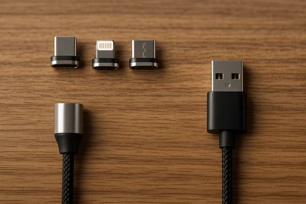
mechanical interface, Pin Map and electrical requirements are mutually
compatible.
Mechanical Compatibility does not ensure Electrical Compatibility
This is especially important for custom magnetic systems because two mating
halves may physically attract even when their electrical functions are not
identical.

Where incompatible accessories could be connected, engineers can consider:- mechanical keying;
- asymmetric contact layout;
- magnetic polarity coding;
- device detection;
- identification contacts;
- power gating;
- controller-level validation.
Strategy 5: Design the Complete Power Path, Not Just the Pogo Pins
A custom magnetic USB cable can be designed for higher charging current,
but current capability is a property of the complete conductive path.
A simplified path is:
    Charger
    →
    USB Connector
    →
    Cable Conductors
    →
    Magnetic Connector Termination
    →
    Pogo Pins / Contacts
    →
    Mating Target
    →
    Device PCB
    →
    Charging Electronics
The complete path resistance can be represented as:
    Rpath =
    RUSB +
    Rcable +
    Rtermination +
    Rpogo +
    Rinterface +
    Rtarget +
    Rdevice
The voltage drop is:
Vdrop = I × RpathThe resistive loss is:
Ploss = I² × Rpath

Fast-charging capability should therefore be validated using the actual
cable length, conductor structure, connector, mating target and device
electronics.
A USB-C Plug Does Not Define the Magnetic Interface Power Rating
Using USB-C on the source side does not automatically mean the custom
magnetic end supports a particular charging power.

The magnetic interface must provide all electrical paths required by the
intended charging architecture.
Parallel Power Contacts Need Current-Sharing Validation
Some custom magnetic cable designs use several contacts in parallel for
power or return.

Current may not divide equally between those contacts.
Branch current can be affected by:
- pogo pin working stroke;
- contact resistance variation;
- target flatness;
- connector tilt;
- termination resistance;
- cable conductor routing.
Current capability should therefore be confirmed through complete-path
voltage-drop and temperature-rise testing.
Strategy 6: Treat Data as a Separate Channel-Engineering Problem
Some magnetic USB cables are designed only for power.

Others may carry project-specific control signals or validated data paths.

The presence of several pogo pins does not automatically mean that the
cable supports a particular USB data rate.
Data performance can depend on:
- signal and return allocation;
- contact geometry;
- contact pitch;
- PCB transition;
- cable construction;
- reference-path continuity;
- crosstalk;
- complete channel length.
A specific USB or other high-speed requirement should therefore be
validated across the complete channel.
Pin Count Does Not Equal USB Capability
| Magnetic Interface | Possible Function |
|---|---|
| Basic Multi-Contact Interface | Power and return |
| Additional Detection Contact | Power plus device / cable detection |
| Additional Signal Contacts | Project-specific control or communication |
| Validated Data Architecture | Defined protocol only after complete-channel design and testing |
Strategy 7: Design the Exposed Contact State Before Finalizing the Cable
A magnetic interface may leave conductive targets or pogo pins exposed when
the cable is disconnected.

This condition should be treated as a normal product state rather than an
exception.
Engineers should consider:
- whether power remains present on exposed contacts;
- foreign conductive objects;
- metallic debris;
- dust;
- skin oil;
- sweat;
- moisture;
- cleaning agents;
- accidental contact between adjacent targets.
Magnetic Attachment Should Not Automatically Enable Power
Magnetic attraction can begin before all contacts reach their final
electrical position.

A possible system sequence is:


    Cable Approaches
    →
    Magnetic Capture
    →
    Mechanical Seating
    →
    Required Contacts Engage
    →
    Connection Validated
    →
    Power Enabled


Whether detection or power gating is required depends on the project
voltage, current and risk analysis.
The Magnetic Tip Is Not Automatically a Dustproof Plug
Leaving a detachable adapter inside a device receptacle may reduce direct
exposure of some internal port surfaces.

However, it should not automatically be described as a sealed dust or water
barrier.

The environmental performance depends on:- adapter fit;
- device receptacle geometry;
- surrounding enclosure;
- connector sealing;
- mated and unmated states;
- actual test conditions.
Magnets Add a Metallic-Debris Failure Mode
Permanent magnets can attract ferromagnetic particles toward the cable
interface.
Metallic debris may:
- prevent full seating;
- scratch contact targets;
- change pogo pin compression;
- bridge adjacent conductive areas;
- increase local resistance.
Connector geometry and maintenance access should therefore account for the
actual use environment.
Cable Durability Should Be Evaluated Separately from Connector Life
The magnetic connector and the flexible cable experience different wear
mechanisms.

A connector may remain electrically functional while the cable jacket,
conductor or strain-relief region begins to degrade.
A cable durability program can evaluate:
- repeated bending;
- torsion;
- connector pull force;
- strain-relief fatigue;
- jacket abrasion;
- temperature exposure;
- electrical continuity during flexing.
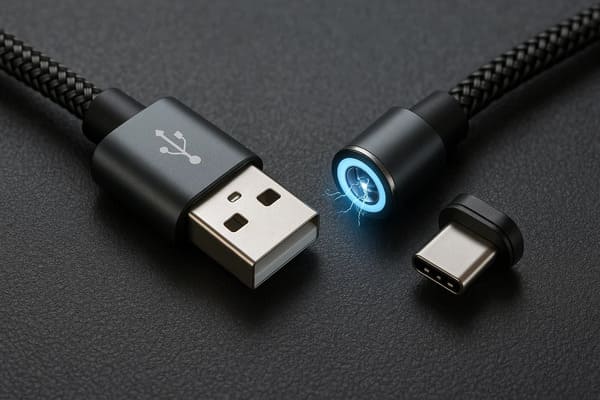
separately from magnetic connector mating life.
A Braided Jacket Does Not Automatically Mean Industrial Durability
Jacket construction can improve handling or abrasion performance in some
applications, but final cable durability also depends on:- internal conductor structure;
- shielding where required;
- bend radius;
- strain relief;
- connector termination;
- flexing direction;
- environmental exposure.
Cable construction should therefore be selected according to the actual
product duty cycle rather than appearance alone.
Custom Magnetic Cable Design for Device Fleets
For enterprise handhelds, tablets and other managed equipment, a custom
magnetic cable architecture can be designed as part of the complete device
ecosystem.

The goal is not simply to use one cable everywhere.

The goal is to deliberately define a controlled interface family.
This may include:
- common connector geometry;
- common magnetic orientation;
- shared Pin Map where appropriate;
- device-specific detection;
- compatible voltage ranges;
- controlled charger selection;
- defined cable lengths;
- service and replacement rules.
Custom Magnetic USB Cable vs Standard USB Cable
| Design Requirement | Custom Magnetic Cable | Standard Plug Cable |
|---|---|---|
| Repeated User Mating | Can move routine mating to magnetic interface | Occurs directly at receptacle |
| Blind / Low-Visibility Connection | Magnetic capture can assist approach | Usually requires plug alignment |
| Breakaway Behavior | Can be designed into interface | Depends on plug / latch architecture |
| Third-Party Compatibility | Often project-specific | Standard ecosystem generally stronger |
| Electrical Architecture | Custom Pin Map possible | USB interface already standardized |
| Development Effort | Requires custom mechanical and electrical validation | Less custom interface development |
When Is a Custom Magnetic USB Cable Worth Considering?
It can be worth evaluating when:
- the device is connected and disconnected frequently;
- device-port replacement is expensive or difficult;
- blind or one-handed connection is desirable;
- controlled cable breakaway is useful;
- a dedicated OEM charging ecosystem is acceptable;
- the mechanical and electrical interface can be validated as one system.
When May Standard USB Be the Better Choice?
A magnetic cable should not replace a conventional USB interface simply
because magnetic mating feels more convenient.
Standard USB may remain preferable when:
- universal accessory compatibility is essential;
- standardized data performance is the main requirement;
- the device connects infrequently;
- a proprietary accessory ecosystem is undesirable;
- the environment contains difficult-to-control metallic debris;
- custom connector development cannot be justified.
Recommended Custom Magnetic USB Cable Validation Plan
| Validation Area | Recommended Evaluation |
|---|---|
| Device-Side Interface | Verify adapter or custom target fit and mechanical support |
| Magnetic Capture | Evaluate normal and offset approach conditions |
| Final Seating | Confirm all required contacts reach the intended state |
| Retention | Measure normal cable handling loads |
| Breakaway | Evaluate axial, peel and off-axis pull directions |
| Power Path | Measure complete-path voltage drop and temperature rise |
| Parallel Contacts | Evaluate current sharing where applicable |
| Data Channel | Validate the complete channel for the required signal interface |
| Partial Mating | Test tilted and incomplete seating states |
| Exposed Contacts | Evaluate contamination and electrical state while disconnected |
| Metallic Debris | Assess seating and bridging risk where relevant |
| Cable Flex | Evaluate repeated bending and strain-relief fatigue |
| Mating Life | Monitor contact wear and resistance under defined conditions |
Information Required for a Custom Magnetic USB Cable Project
| Project Input | Information to Provide |
|---|---|
| USB-Side Interface | USB-A, USB-C or another host / charger connector |
| Device-Side Architecture | Detachable adapter or dedicated OEM magnetic interface |
| Pin Map | Function of every magnetic-side contact |
| Voltage | Operating voltage and relevant system conditions |
| Current | Continuous current, peak current and charging duty cycle |
| Data Requirement | Power only, control signals or defined data requirement |
| Cable Length | Required overall cable length |
| Connector Envelope | Maximum magnetic head length, width and height |
| Working Stroke | Minimum, nominal and maximum pogo pin compression where applicable |
| Retention | Desired seated holding behavior |
| Breakaway | Desired separation direction and use condition |
| Environment | Dust, sweat, moisture, oil, cleaning or metallic debris exposure |
| Lifecycle | Required cable flex and connector mating profile |
| Project Files | 2D drawing, 3D model, device assembly or PCB layout |
Frequently Asked Questions
Can magnetic USB cables prevent device-port wear?
They can reduce repeated direct insertion into the original device
receptacle when a compatible adapter or dedicated magnetic interface remains
attached. They do not eliminate all connector or cable wear.
Does leaving the magnetic adapter in the USB port completely protect the port?
No. It can reduce insertion cycles, but lateral loads on the adapter can
still be transferred into the underlying receptacle.
Is a magnetic USB cable automatically dustproof?
No. A retained adapter may reduce exposure of some internal receptacle
surfaces, but environmental protection depends on the complete fit and
enclosure design.
Do magnetic USB cables automatically support fast charging?
No. Charging capability depends on the cable conductors, connector contacts,
mating targets, device electronics and complete resistance and thermal path.
Do custom magnetic USB cables support data?
They can be designed for data, but the required signal paths and complete
channel must be engineered and validated for the intended interface.
Does more pogo pin contacts mean faster data?
No. Pin count only provides additional conductive paths. Signal integrity
depends on contact arrangement, returns, PCB transitions, cable construction
and complete-channel behavior.
Are magnetic USB cables safer if somebody pulls the cable?
Controlled breakaway may reduce cable load transferred to the device in
some conditions, but actual behavior depends on retention, pull direction,
connector geometry and device mechanics.
Can one magnetic cable charge an entire device fleet?
Potentially, if the product family is intentionally designed with compatible
mating geometry, Pin Maps, voltage requirements and power-control logic.
Physical compatibility alone is not enough.
Are magnetic USB cables wear-free?
No. Magnetic contacts, pogo pins, target surfaces, cable jackets and strain
relief can all experience wear during repeated use.
What is the difference between a magnetic USB adapter cable and a custom OEM magnetic cable?
An adapter architecture uses an existing USB receptacle with a removable
tip, while a dedicated OEM architecture integrates the magnetic electrical
interface directly into the product design.
What information is needed to customize a magnetic USB cable?
Provide the USB-side connector, device-side interface, Pin Map, voltage,
current, data requirements, cable length, connector envelope, retention and
breakaway requirements, environment and product drawings.
Request a Custom Magnetic USB Cable Engineering Review
Explore

    custom magnetic connector solutions

for device-side charging and removable electrical interfaces.

Review

    pogo pin and spring-contact solutions

for project-specific contact layouts and terminations.

Learn more about CTP development and manufacturing capabilities on the

    About Us page
.

Submit the cable interface, Pin Map, voltage, current, cable length,
data requirement, connector dimensions and project drawings through the

    Get Quote & Samples page
.


    CTP can review magnetic cable geometry, pogo pin contact layout,
    working stroke, device-side mating targets, magnetic retention,
    breakaway behavior, cable conductor structure and USB-side termination
    for custom magnetic cable assemblies. Final charging capability, data
    performance, environmental protection, cable flex life and connector
    mating life depend on the approved cable design and project-specific
    validation.
CTP ENGINEERING PATHS
Choose the right path for your project
Move from application requirements to a connector pair, a data-capable cable assembly, or a charging cable configuration. Final specifications are confirmed against an approved drawing and project validation plan.
Magnetic Connectors
Connector geometry, pin layout, mechanical integration and OEM/ODM review.
Engineering overview → 02Magnetic Data Cables
Power and signal allocation, cable exit, interface selection and assembly review.
Cable engineering → 03Magnetic Charging Cables
Browse the complete cable catalog and shortlist a starting structure for customization.
View cable catalog →