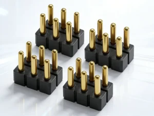
Developing custom magnetic pogo pins does not always require an engineering team to begin with a completely blank design. Many new connector projects share structural requirements with previously developed products: similar pin counts, mounting directions, working strokes, magnetic layouts, cable exits or enclosure interfaces.
When these previous designs are organized into a searchable engineering library, they can provide a useful starting point for new product development. Engineers can compare proven structures, identify compatible components and concentrate prototype testing on the parts of the design that are genuinely new.
The value of such a library is not simply the number of samples stored in a cabinet. Its real value depends on whether each reference design is connected to controlled drawings, materials, dimensional limits, manufacturing methods and previous test results.
A large sample library does not eliminate the need for custom engineering. It helps the team find a more informed starting point. The selected baseline must still be checked against the new project’s current, space, force, environment and production requirements.
What Is a Magnetic Pogo Pin Design Library?
A magnetic pogo pin design library is a controlled collection of previous connector structures, components and manufacturing records that can be referenced during new product development.
Depending on the supplier, the library may include:
- individual pogo pin structures;
- multi-pin connector housings;
- magnetic connector modules;
- mating-pad layouts;
- magnet arrangements and polarity records;
- PCB, FPC, wire and cable terminations;
- overmolded magnetic cable heads;
- mounting and alignment features;
- assembly fixtures;
- test fixtures;
- approved drawings and revision records;
- previous inspection and validation data.
A physical sample by itself has limited engineering value. To support R&D efficiently, the sample should be linked to information that explains how it was designed and manufactured.
Useful reference data
| Reference category | Information that should be available |
|---|---|
| Contact structure | Diameter, free height, working stroke, spring force, tip geometry and mounting method. |
| Electrical design | Pin allocation, intended current path, contact-resistance criteria and insulation spacing. |
| Magnetic system | Magnet dimensions, position, polarity, retention direction and mating behavior. |
| Mechanical interface | Housing dimensions, locating features, mounting points, mating direction and enclosure reference. |
| Termination | PCB, SMT, DIP, FPC, wire, cable, soldering, crimping or overmolding configuration. |
| Production history | Tooling status, assembly method, known process limits and inspection approach. |
Why Starting from a Reference Design Can Accelerate R&D
The early phase of connector development often contains more uncertainty than actual drawing work. Engineers first need to determine whether the requested size, current, force, pin count and mounting structure can coexist within the available space.
A reference-design library can reduce this uncertainty by showing how similar requirements were previously resolved.
Faster structural comparison
Instead of evaluating every possible connector architecture, the engineering team can compare a smaller number of relevant baselines, such as:
- circular versus linear connector layouts;
- single-row versus multi-row contact arrays;
- PCB-mounted versus wire-terminated structures;
- integrated housing versus separate pogo pins;
- flat mating pads versus recessed contact surfaces;
- side-exit versus rear-exit cable assemblies;
- magnetic retention versus combined magnetic and mechanical retention.
This makes the initial design discussion more concrete. The customer can evaluate real dimensions, mating behavior and assembly methods rather than discussing only an abstract concept.
Earlier identification of incompatible requirements
Previous designs can also expose common engineering conflicts.
Examples include:
- the requested current is too high for the available contact area;
- the required working stroke does not fit the enclosure height;
- the magnetic force needed for retention is higher than the desired breakaway force;
- the pin pitch is too small for the voltage or contamination environment;
- the proposed cable exit interferes with the enclosure assembly;
- the customer requires a standard housing but a nonstandard pin map;
- the selected structure cannot be assembled consistently at the planned volume.
Finding these conflicts before tooling and detailed prototyping can prevent unnecessary design loops.
Three Levels of Design Reuse
Reference designs are not reused in the same way for every project. A useful engineering library should support several levels of customization.
Level 1: Existing structure with limited changes
An existing design may be suitable when the new project has similar:
- pin count;
- connector dimensions;
- mating direction;
- current requirement;
- mounting method;
- retention-force range.
Typical changes may include wire length, cable color, connector marking, pin assignment or packaging.
This route can reduce development effort because the housing, pogo pin structure and primary assembly method are already defined.
Level 2: Platform-based semi-custom design
A platform design reuses several proven components while modifying the surrounding structure.
For example, the project may reuse:
- an existing pogo pin;
- an existing mating-pad diameter;
- a known magnet size;
- a validated cable construction;
- a previous PCB termination method.
The supplier then develops a new housing, pin arrangement, magnet location or enclosure interface around those components.
This is often the most useful approach for custom magnetic connectors because it preserves known component behavior while allowing the external geometry to match the customer’s device.
Level 3: Full custom development
A full custom design may be required when the project introduces:
- a new contact diameter or stroke;
- an unusual spring-force requirement;
- a very restricted connector envelope;
- a new sealing architecture;
- a new high-current path;
- a unique multi-pin signal layout;
- a special mating sequence;
- a new manufacturing or installation method.
Even in a full custom project, the design library remains useful. Engineers can still reference previous spring structures, plating systems, housing materials, assembly fixtures and known failure modes.
How Reusable Contact Platforms Support Faster Feasibility Reviews
The pogo pin is one of the most critical components in the interface. Its geometry influences working stroke, contact force, installed height, current path and manufacturing tolerance.
A structured contact library allows engineers to compare existing options by:
- barrel diameter;
- plunger diameter;
- free height;
- recommended working height;
- total travel;
- spring-force range;
- tip geometry;
- mounting type;
- termination method;
- material and plating specification.
Instead of selecting a pogo pin only because it fits the drawing, engineers can identify which existing contact platform comes closest to the required mechanical and electrical operating point.
Example feasibility questions
- Does an existing pogo pin provide enough stroke for the tolerance stack?
- Will the spring force remain acceptable when multiplied by the total pin count?
- Can the selected pin be installed using the planned PCB or housing process?
- Is the tip geometry compatible with the mating-pad size?
- Is the contact structure suitable for repeated docking or mainly static compression?
- Can the existing component be produced at the expected volume?
Reusing Magnetic Architectures Without Copying Them Blindly
Magnet layouts can also provide useful design references, especially for projects requiring automatic alignment or controlled breakaway.
A previous layout may help engineers understand:
- how the connector approaches the mating surface;
- where the strongest attraction occurs;
- whether the assembly tends to rotate;
- how the magnetic force interacts with pogo pin spring force;
- how much space the magnets occupy;
- whether steel components influence the magnetic path;
- how polarity is controlled during assembly.
However, the same magnet arrangement can behave differently when the housing dimensions, air gap, steel structure, pin force or cable load changes.
Previous magnet arrangements can be used as a design reference, but the retention and breakaway forces must be rechecked in the new assembled structure.
Why Historical Failure Data Is More Valuable Than Sample Quantity
A large product library becomes significantly more useful when it includes records of what did not work.
Historical engineering records may reveal problems such as:
- insufficient pogo pin compression after assembly;
- uneven spring force across a multi-pin array;
- magnet polarity installed incorrectly;
- housing deformation after molding;
- excessive voltage drop in a long cable;
- contact wear caused by side sliding;
- overmold cracking near the cable exit;
- metallic debris collecting around exposed magnets;
- misalignment caused by a weak mechanical guide;
- difficult customer assembly due to an uncontrolled tolerance stack.
These records allow engineers to avoid repeating known design mistakes. They also help determine which characteristics should receive more attention during a new prototype review.
Reference Designs Can Reduce Prototype Scope, Not Eliminate Prototypes
A design library can reduce the number of unknowns, but every new project still contains application-specific conditions.
For example, an existing connector may already demonstrate suitable contact geometry and magnetic alignment. The new prototype can then focus on:
- fit inside the customer’s enclosure;
- actual working compression;
- device-side PCB tolerance;
- cable pull and bending behavior;
- voltage drop in the new cable length;
- temperature rise at the customer’s load;
- user docking and separation behavior;
- contamination in the intended environment.
This produces a more focused prototype plan. Instead of retesting every known characteristic, the team can concentrate on the changed interfaces and newly introduced risks.
What Must Always Be Revalidated
Even when a design reuses existing components, some characteristics should not be assumed to remain unchanged.
| Changed condition | What may need to be revalidated |
|---|---|
| New housing dimensions | Alignment, working stroke, installed height and housing strength. |
| Different magnet gap | Retention, breakaway, orientation and attraction behavior. |
| Longer cable | Voltage drop, conductor temperature, cable pull and user handling. |
| Higher current | Contact resistance, current sharing, voltage drop and temperature rise. |
| Different pin map | Offset-mating safety, contact sequencing and incorrect-orientation risks. |
| New environment | Contamination, corrosion, sealing, cleaning and material compatibility. |
| Different production process | Dimensional stability, assembly repeatability, inspection and process capability. |
How Engineers Select a Suitable Baseline Design
A reference design should be selected through a structured comparison rather than by visual similarity alone.
Step 1: Define the fixed constraints
Start with requirements that cannot easily be changed:
- maximum connector envelope;
- device-side mounting location;
- required number of circuits;
- continuous current;
- mating direction;
- environmental limitations;
- required cable or PCB termination.
Step 2: Identify adjustable parameters
Some characteristics may remain flexible during concept development:
- exact outer shape;
- magnet size;
- pin arrangement;
- working stroke within an acceptable range;
- cable-exit direction;
- housing material;
- retention-force target.
Step 3: Compare reference families
The engineering team can then shortlist previous designs that match the greatest number of fixed requirements.
Step 4: Record the differences
For each candidate reference, document:
- features that can be reused directly;
- features requiring modification;
- new tooling requirements;
- new technical risks;
- tests that must be repeated;
- possible effects on cost and schedule.
Step 5: Select the lowest-risk architecture
The best baseline is not necessarily the design requiring the fewest drawing changes. It is the architecture that satisfies the project requirements with the clearest manufacturing and validation path.
Design Library Decision Matrix
| Project condition | Recommended route |
|---|---|
| Dimensions and function closely match an existing connector | Evaluate an existing structure with minor cable, pin-map or cosmetic changes. |
| Contact requirements are familiar but the enclosure is new | Reuse the contact and termination platform while developing a new housing. |
| Magnetic behavior is known but pin count changes | Reuse the magnetic concept while redesigning the contact and mechanical layout. |
| Current, stroke and available space are outside existing ranges | Begin a new contact and connector development using historical data only as reference. |
| Application has new safety or environmental requirements | Use existing geometry cautiously and create an application-specific validation plan. |
How a Design Library Supports Cross-Functional Teams
The same reference system can provide different value to different members of the customer’s development team.
Mechanical engineers
They can compare:
- housing dimensions;
- mating directions;
- retention methods;
- alignment features;
- mounting structures;
- tolerance requirements.
Electrical engineers
They can review:
- pin assignments;
- power and ground layouts;
- current paths;
- contact spacing;
- detection contacts;
- previous voltage-drop or resistance data.
Industrial designers
They can evaluate:
- connector appearance;
- surface integration;
- cable-head proportions;
- mating behavior;
- user interaction;
- available color and overmolding options.
Manufacturing engineers
They can review:
- assembly sequence;
- fixture requirements;
- installed-height controls;
- magnet-polarity controls;
- test-fixture concepts;
- known production bottlenecks.
Procurement teams
They can compare:
- existing versus new tooling;
- component availability;
- production readiness;
- customization scope;
- likely development effort;
- long-term revision control.
Common Misunderstandings About Large Product Libraries
“More samples always mean faster development”
Not necessarily. A large number of unclassified samples can slow down selection. The library must be searchable by engineering parameters rather than only by appearance or customer name.
“An existing sample has already passed every required test”
Previous test results apply only to the tested structure, materials and conditions. A new application may introduce different current, enclosure, environment or mating behavior.
“Using an existing design means no tooling is required”
The pogo pin or magnet may already exist, while a new housing, insert, cable mold or assembly fixture is still needed.
“A similar-looking connector will perform the same way”
Small changes in stroke, spring force, magnet gap, wire length or pad layout can produce different mechanical and electrical behavior.
“The oldest design is the most proven”
An older design may have useful production history, but its materials, tooling, customer requirements or inspection methods may no longer match the current project.
Information Needed to Search the Design Library Effectively
The supplier can identify relevant reference designs more accurately when the customer provides clear search inputs.
- device type and application;
- required pin count;
- power, ground and signal allocation;
- continuous and peak current;
- available connector dimensions;
- preferred shape;
- mating direction;
- PCB, FPC, wire or cable termination;
- required retention or breakaway behavior;
- working environment;
- mating-cycle target;
- prototype quantity;
- expected annual volume;
- 2D drawings, 3D models or enclosure images.
Without these inputs, the supplier may be able to provide visually similar samples, but not necessarily technically suitable ones.
Frequently Asked Questions
Does a large design library mean every magnetic connector is available from stock?
No. A design library may contain samples, drawings, component platforms and previous project structures. Some may require new materials, tooling, cable assemblies or production preparation before they can be supplied.
Can an existing reference design be copied directly into a new device?
Only after the connector has been checked against the new device’s dimensions, current, working stroke, magnetic force, mounting method and environmental requirements.
How does a reference design reduce prototype time?
It can reduce the number of structural options that must be explored and allow engineers to focus testing on the differences between the old and new applications.
What is the difference between a product SKU and a reference design?
A product SKU is normally a controlled saleable item or material number. A reference design may be a sample, drawing, platform, prototype or previous custom structure that is not currently stocked or sold as a standard item.
Can previous test data be reused?
Previous data can support feasibility analysis, but the customer and supplier should determine whether the tested structure, material and conditions are sufficiently similar to the new application.
When is full custom development still necessary?
Full custom development may be required when the required current, stroke, size, pin arrangement, environment or manufacturing method falls outside the practical range of existing platforms.
Does using an existing pogo pin reduce project risk?
It can reduce uncertainty related to the contact component, but the complete connector still depends on housing tolerances, magnetic force, mating pads, cables, PCB layout and final assembly.
Conclusion
A structured design library can help engineering teams develop custom magnetic pogo pins more efficiently by providing real reference points for contact structure, magnetic layout, housing design, mounting and cable termination.
The benefit does not come from sample quantity alone. It comes from connecting previous designs to drawings, materials, manufacturing knowledge, inspection methods and test history.
The most effective approach is to reuse known components where they fit, redesign the interfaces that are specific to the new device and revalidate every characteristic affected by the change.
CTP supports custom development of magnetic pogo pin connectors, magnetic cable assemblies, pogo pin connector assemblies and individual pogo pins.
To identify a suitable baseline for a new project, submit your pin count, current requirements, available space, mating direction, termination method and device drawings through our Get a Quote & Samples page. The engineering team can then compare relevant reference structures and define which elements can be reused, modified or developed from the beginning.