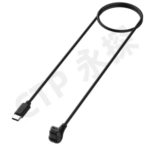
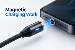
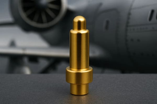
An aerospace pogo pin connector is a spring-loaded interconnect designed for applications where compact packaging, repeated mating, tolerance compensation or blind docking is required. Its suitability for an airborne or aerospace-related system depends not only on the pogo pin itself, but on the complete electromechanical interface.
Spring force, working stroke, contact resistance, plating, housing tolerance, vibration response, current path and environmental protection must be evaluated together. A connector that performs well during a static bench test may still produce intermittent contact, excessive voltage drop or mechanical wear when exposed to vibration, thermal cycling and repeated maintenance.
“Aerospace-grade” should not be treated as a material or connector category by itself. The connector must be designed and validated against the actual vibration, shock, temperature, contamination, current and service-life requirements of the application.
Where Aerospace Pogo Pin Connectors Are Used
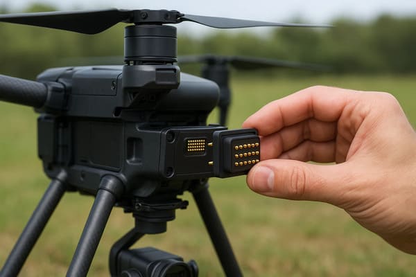
Pogo pin connectors are commonly considered when a conventional friction connector is too large, difficult to access or unsuitable for frequent docking. Potential application areas include:
- avionics test fixtures and programming interfaces;
- replaceable sensor or communication modules;
- UAV charging and docking stations;
- ground-support and diagnostic equipment;
- portable inspection instruments;
- removable battery or power modules;
- cockpit or cabin service interfaces;
- blind-mating PCB and enclosure assemblies.
The correct architecture may use individual pogo pins, a multi-pin plastic housing, a PCB-mounted connector module, a wire-terminated assembly or a magnetic docking system. The selection depends on whether the interface is permanent, serviceable, repeatedly mated or exposed to movement.
1. Start with the System Requirement, Not the Pogo Pin
One of the most common design mistakes is selecting a pogo pin from a catalogue before defining the complete interface requirement.
The engineering process should begin with the following questions:
- How many power, ground and signal circuits are required?
- What are the continuous and peak currents?
- Will the connector be mated during normal operation or only during maintenance?
- What vibration and shock profiles will the equipment experience?
- How much axial, radial and angular misalignment must be tolerated?
- What is the maximum available connector height?
- Is positive mechanical locking required?
- Will the interface be exposed to moisture, dust, fuel, oil or salt contamination?
- What mating-cycle target must be demonstrated?
These inputs determine the required spring force, working stroke, contact material, plating, pin pitch, housing structure and validation plan.
2. Vibration and Shock: Preventing Intermittent Contact
In a vibrating system, the key electrical risk is not always complete connector separation. Short-duration changes in contact force can produce fluctuations in contact resistance or temporary circuit interruption.
A spring-loaded contact compensates for dimensional variation by maintaining axial force against the mating pad. However, reliable performance requires the pogo pin to remain within its designed working-stroke range throughout the full vibration and tolerance condition.
The following factors influence dynamic contact stability:
- spring force at the nominal working position;
- available compression margin;
- moving mass of the plunger;
- connector retention method;
- housing stiffness;
- PCB and enclosure movement;
- contact-tip and pad geometry;
- vibration frequency, direction and acceleration;
- cable pull and side loading.
Recommended vibration validation
During vibration testing, engineers should monitor the electrical circuit continuously rather than checking resistance only before and after the test. A suitable validation plan may include:
- real-time discontinuity monitoring;
- contact-resistance measurement before and after vibration;
- inspection for plunger, spring or housing damage;
- testing in multiple axes;
- testing at minimum and maximum dimensional conditions;
- testing after environmental aging and mating-cycle exposure.
The pass criteria should be agreed before testing. They may include maximum interruption duration, maximum resistance change and acceptable mechanical condition.
3. Working Stroke and Tolerance Stack
A pogo pin has a total travel and a recommended working-stroke region. The connector should be designed so that every contact remains inside this region after all dimensional tolerances are accumulated.
The tolerance stack may include:
- pogo pin installed height;
- PCB thickness and flatness;
- solder-joint height;
- housing dimensions;
- mating-pad position;
- gasket compression;
- fastener and enclosure tolerances;
- thermal expansion.
If the compression is too low, the contact may not generate sufficient normal force. If it is too high, the pogo pin may bottom out, increase wear, damage the housing or apply excessive force to the PCB.
| Condition | Possible result |
|---|---|
| Insufficient compression | Low contact force, unstable resistance or open circuit during movement. |
| Excessive compression | Spring overstress, bottoming, housing deformation or PCB loading. |
| Uneven compression | Different contact forces across a multi-pin array and inconsistent electrical performance. |
| Limited stroke margin | Greater sensitivity to manufacturing and assembly variation. |
4. Contact Materials, Plating and Fretting Risk
Repeated micro-motion at a contact interface can damage the plating surface and increase contact resistance. This mechanism is often associated with fretting wear and corrosion, particularly where vibration, contamination and low contact force occur together.
The material and plating system should be selected according to:
- required spring performance;
- mating-cycle target;
- electrical load;
- operating temperature;
- humidity and corrosion exposure;
- cleaning method;
- contact-tip and pad materials.
Copper alloys are commonly used for conductive pogo pin components because they combine electrical conductivity with mechanical properties suitable for small precision parts. Gold-based contact finishes are often selected for corrosion resistance and stable low-level contact performance, but the complete underplating and thickness specification must be defined for the application.
No plating system eliminates wear under every condition. Validation should include inspection and resistance measurement after vibration, environmental exposure and repeated mating.
5. Spring Force Is a System-Level Trade-Off
Higher spring force can improve contact stability, but it also increases the total force required to mate or retain a multi-pin connector.
For a connector with multiple pogo pins, the total spring load is approximately the sum of the individual contact forces at the working position. Additional force may also be required to compress a gasket or maintain enclosure contact.
The connector retention system must maintain the required pogo pin compression while also overcoming gasket force, cable load, dynamic separation force and manufacturing variation.
Possible retention methods include:
- mechanical latches;
- screws or fasteners;
- enclosure compression;
- guide rails;
- magnetic retention;
- combined magnetic and mechanical retention.
A magnetic pogo pin connector can support blind mating and controlled breakaway, but it may not be appropriate where the interface must remain locked during high cable tension or severe movement.
6. Current Capacity, Voltage Drop and Temperature Rise
The current capability of an aerospace pogo pin connector should be based on the complete current path rather than on the pogo pin diameter alone.
The current path may include:
- the plunger and barrel;
- the internal spring or separate conductive path;
- the mating pad;
- the solder joint;
- the PCB trace or busbar;
- the wire or cable;
- the final termination.
Electrical loss increases with resistance, and the resulting heat becomes more significant as current rises. Engineers should therefore verify:
- initial contact resistance;
- voltage drop at the required current;
- temperature rise at continuous load;
- performance at elevated ambient temperature;
- resistance after vibration and mating cycles;
- current sharing when multiple pins are connected in parallel.
Using several contacts in parallel can increase current capacity, but equal current sharing should not be assumed. Differences in compression, resistance, PCB routing and solder joints may cause one contact to carry more current than the others.
7. Signal Integrity and EMI Design
Pogo pins can carry control, detection and selected data signals, but signal suitability depends on the electrical architecture.
For higher-frequency signals, the interface must be evaluated for:
- signal-to-ground arrangement;
- pin pitch and coupling;
- return-path continuity;
- connector transition geometry;
- PCB stack-up;
- cable impedance;
- shield termination;
- insertion loss, return loss and crosstalk.
A metal housing or shield can support electromagnetic compatibility, but it does not automatically create a complete shielding solution. Shield continuity, bonding points, enclosure seams and cable termination must be designed as one system.
For high-speed interfaces, simulation and physical testing may be required before the connector design is released.
8. Blind Mating and Mis-Mating Prevention
Blind mating can simplify maintenance and module replacement when the connector is located inside an enclosure or cannot be seen during assembly.
A reliable blind-mating interface normally combines several features:
- lead-in chamfers or guide surfaces;
- mechanical keys;
- asymmetric pin layouts;
- locating posts;
- large enough mating pads;
- controlled radial float;
- optional magnetic orientation.
Magnets can help attract and orient the mating halves, but they should not be the only feature preventing reversed or offset connection. Mechanical keying is recommended where an incorrect orientation could connect power to the wrong circuit.
9. Environmental Sealing and Contamination Control
A pogo pin connector can be integrated into a sealed module, but the pogo pin alone does not ensure a specific environmental protection level.
Sealing performance depends on the complete assembly, including:
- housing and insert-molding design;
- O-rings and gaskets;
- adhesives and potting compounds;
- PCB sealing;
- wire-entry sealing;
- drainage paths;
- contact spacing;
- surface contamination control.
Potential aerospace and ground-support contaminants may include moisture, dust, salt, cleaning chemicals, oils and metallic particles. The connector should be evaluated under the actual expected exposure conditions.
Environmental ratings should only be stated after the complete connector or device assembly has passed the relevant test procedure.
10. Qualification Should Follow the Application Profile
A robust qualification plan should be based on the end-use environment rather than on a generic claim that the connector is suitable for aerospace.
| Validation area | Typical measurements |
|---|---|
| Dimensional inspection | Installed height, stroke, pitch, housing dimensions and alignment. |
| Electrical performance | Contact resistance, insulation resistance, voltage drop and temperature rise. |
| Mechanical performance | Spring force, retention force, mating force, side load and durability. |
| Dynamic testing | Vibration, shock and real-time electrical discontinuity. |
| Environmental testing | Temperature cycling, humidity, corrosion, dust and fluid exposure. |
| Life testing | Mating cycles followed by resistance, force and visual inspection. |
The test severity, duration, sample quantity and acceptance criteria should be defined by the customer’s system requirements and applicable qualification plan.
Pogo Pin Connector vs. Conventional Connector
| Design requirement | Pogo pin connector | Conventional plug connector |
|---|---|---|
| Blind mating | Can be designed with guide features, float or magnets. | Usually requires defined plug alignment. |
| Tolerance compensation | Axial spring travel can absorb dimensional variation. | Depends on receptacle and terminal geometry. |
| Positive locking | Requires a separate latch, fastener or enclosure feature. | Often available as part of the connector system. |
| Repeated docking | Suitable when stroke, plating and alignment are controlled. | Depends on contact and shell durability. |
| High-speed standardized data | Requires custom signal-integrity validation. | Standardized interfaces may simplify compliance. |
When a Pogo Pin Connector May Not Be the Best Choice
A pogo pin interface may not be the preferred architecture when:
- a certified standardized connector is mandatory;
- the cable must remain mechanically locked under high tension;
- the system carries very high-speed data without room for signal validation;
- the contact surface cannot be protected from conductive debris;
- the available compression tolerance is too small;
- the interface must remain continuously mated for the full product life;
- field users require a widely available replacement cable or connector.
In these cases, a conventional circular, rectangular, board-to-board or locking connector may be more appropriate.
Information Required for a Custom Aerospace Pogo Pin Connector
Before beginning a custom design, provide as much of the following information as possible:
- pin count and pin assignment;
- continuous and peak current per circuit;
- signal types and data rates;
- available connector area and maximum height;
- mating direction and allowable misalignment;
- required working stroke;
- retention or breakaway-force requirement;
- vibration and shock profile;
- working and storage temperature;
- humidity, corrosion and contamination exposure;
- required mating-cycle target;
- PCB, wire, cable or FPC termination method;
- 2D drawings, 3D models and enclosure references;
- prototype and annual-volume requirements.
These inputs allow the connector manufacturer to evaluate whether an existing structure can be adapted or whether a new housing, pin layout, spring force or tooling design is required.
Frequently Asked Questions
What makes a pogo pin connector suitable for aerospace use?
Suitability depends on whether the complete connector assembly meets the application’s electrical, mechanical and environmental requirements. Important factors include stable contact under vibration, adequate stroke margin, controlled resistance, suitable materials, retention and validated environmental performance.
Can pogo pin connectors withstand vibration?
They can be designed for vibrating systems, but performance must be demonstrated through application-specific testing. Spring force, connector compression, housing stiffness, retention and vibration direction all affect the result.
Are all aerospace pogo pin connectors waterproof?
No. Waterproofing depends on the complete housing, sealing, molding, gasket, PCB and cable-entry design. A specific protection level should only be claimed after testing the assembled connector or device.
Can pogo pin connectors carry avionics data signals?
They can carry control and selected data signals, but higher-speed signals require analysis of pin arrangement, ground return, impedance, shielding and connector transitions. Testing or simulation may be required.
How many mating cycles can an aerospace pogo pin connector achieve?
There is no universal cycle value. Service life depends on plating, contact force, alignment, contamination, electrical load and test conditions. The required target should be defined and validated for the project.
Should an aerospace pogo pin connector use magnetic retention?
Magnetic retention is useful for blind docking and controlled breakaway, but it is not mandatory. Mechanical latches, screws, guide structures or enclosure compression may be more suitable when positive locking is required.
Conclusion
An aerospace pogo pin connector can provide compact packaging, blind mating, axial tolerance compensation and serviceable electrical contact. Its reliability, however, depends on much more than the pogo pin catalogue specification.
The connector should be engineered as part of the complete system. Working stroke, spring force, retention, contact resistance, current path, signal return, enclosure tolerance, vibration and environmental exposure must be considered together.
CTP supports custom development of pogo pin connectors, individual pogo pins, magnetic connector assemblies and magnetic cable assemblies.
For a new aerospace, UAV, test-fixture or rugged-device project, submit your pin assignment, current requirements, available space, vibration conditions and drawings through our Get a Quote & Samples page. The connector architecture can then be reviewed before prototype or tooling development begins.