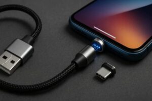
A magnetic USB cable combines a conventional USB-side connection with a
magnet-assisted removable interface near the device or accessory.
Magnets help the two halves locate and remain attached, while conductive
contacts transfer electrical power and, in some designs, data.
Magnetic attachment does not mean wireless charging, and not every magnetic
USB cable supports the same current, USB protocol, data rate or mating life.
These capabilities depend on the complete cable, connector, contact layout
and electronic system.

What Is a Magnetic USB Cable?
A magnetic USB cable is a cable assembly that uses magnets to assist the
connection between two mating electrical interfaces.
One side of the cable may use a conventional interface such as USB-A or
USB-C, while the other side contains a magnetic connector that mates with a
compatible device-side tip, target or custom magnetic connector.
The important point is that the magnets normally provide the
mechanical mating function.
Electrical power still flows through conductive contacts.
Depending on the connector architecture, those contacts may include:- spring-loaded pogo pins;
- flat contact pads;
- fixed conductive contacts;
- project-specific multi-pin contact arrays.
Therefore, not every magnetic USB cable is automatically a pogo pin cable,
although pogo pins are commonly used when spring compliance and repeated
mating are required.
How Does a Magnetic USB Cable Work?
A magnetic USB cable typically operates through four basic functions:- the two connector halves approach each other;
- the magnets assist capture and orientation;
- the electrical contacts touch and reach their designed mating position;
- power or project-specific signals pass through the conductive interface.
A simplified architecture is:
    USB Power / Host
    →
    Cable Conductors
    →
    Magnetic Connector
    →
    Electrical Contacts
    →
    Device-Side Target
    →
    Device Electronics


The magnet does not carry USB data simply because it is magnetic.
The actual electrical path is formed by the contacts and conductors.
Magnetic Attachment Is Not Wireless Charging
Magnetic USB cables are sometimes confused with wireless charging because
both technologies may use magnets for positioning.

They are different electrical architectures.| Interface | How Power Crosses the Interface |
|---|---|
| Magnetic USB Cable | Direct conductive contact |
| Magnetic Pogo Pin Cable | Spring-loaded conductive contact against mating targets |
| Wireless / Inductive Charging | Energy transfer through an electromagnetic coupling system without direct conductive power contacts |
Magnets can be used in both systems for alignment, but the method of energy
transfer is different.
Main Parts of a Magnetic USB Cable
The exact construction varies by product, but a custom magnetic USB cable
may contain several functional elements.| Component | Primary Function |
|---|---|
| USB Connector | Connects the cable to a charger, host or other USB-side device |
| Cable Conductors | Carry power and any required signal paths |
| Magnet Structure | Assists capture, orientation and retention |
| Pogo Pins or Other Contacts | Create conductive electrical paths |
| Mating Targets | Provide the device-side conductive surfaces |
| Insulator | Separates adjacent electrical contacts |
| Housing | Controls mechanical alignment and protects the interface |
| Strain Relief | Reduces mechanical loading where the cable enters the connector |
What Do the Magnets Actually Do?
In a magnetic cable, the magnets primarily contribute to the mechanical
behavior of the interface.
Possible functions include:
- helping the connector halves find each other during approach;
- assisting orientation;
- holding the two halves together after mating;
- allowing a removable or breakaway connection.
Magnets do not independently define:- charging current;
- USB protocol;
- data rate;
- contact resistance;
- waterproof performance;
- mating-cycle life.
These are separate electrical, mechanical and environmental requirements.Magnetic Capture and Final Alignment Are Different
Magnets can pull the connector halves together, but final electrical
alignment should normally be controlled by the connector geometry.| Mating Function | Recommended Control |
|---|---|
| Initial Capture | Magnet arrangement |
| Orientation | Housing shape or asymmetric geometry |
| Final Position | Mechanical locating features |
| Pogo Pin Compression | Mechanical stop and dimensional tolerance stack |
| Seated Retention | Magnetic system and housing structure |
A magnetic snap is useful user feedback, but it is not proof that every
electrical contact is correctly engaged.
How Pogo Pins Work Inside a Magnetic USB Cable
In a pogo pin version, each spring-loaded contact contains a moving plunger
that compresses when it touches the mating target.

The spring allows the contact to accommodate a controlled amount of
variation in the mating height.

This can be useful when a cable must repeatedly connect to a device or
docking surface.
A simplified working-stroke relationship is:
S = Hfree - Hseatedwhere:
- S is actual pogo pin compression;
- Hfree is the free contact height;
- Hseated is the contact height after final mating.
The pogo pin should remain inside its approved working range when the
connector is fully seated.
Total Travel and Working Stroke Are Not the Same Thing
A pogo pin may have more total mechanical travel than the compression
recommended during normal operation.

The connector housing should normally prevent the contact from being
repeatedly compressed to its mechanical limit.| Condition | Possible Result |
|---|---|
| Insufficient Compression | Unstable or intermittent electrical contact |
| Approved Working Stroke | Intended contact force and electrical state |
| Excessive Compression | Spring bottoming, target wear or unnecessary structural loading |
Do Magnetic USB Cables Reduce Port Wear?
They can reduce how frequently a conventional device port is directly
inserted and removed when the magnetic architecture leaves a compatible
adapter or target attached to the device.

However, the magnetic interface itself still experiences mechanical wear.
Possible wear sources include:
- lateral sliding during mating;
- angled attachment;
- contamination;
- vibration;
- incorrect working stroke;
- repeated contact with the mating target;
- powered separation.
A magnetic cable should therefore not be described as wear-free.Self-Wiping Does Not Mean Self-Cleaning
Some pogo pin and target geometries create limited relative movement when
the connector mates.

This movement may disturb light surface films, but it does not ensure removal of:- dust;
- oil;
- fibers;
- corrosion;
- abrasive particles;
- metallic debris.
Contact cleanliness and wear should be evaluated under the actual
application conditions.
How Does a Magnetic USB Cable Carry Power?
Charging current flows through the complete conductive path, not through
the magnetic structure itself.
A simplified charging path is:
    Charger
    →
    USB Connector
    →
    Cable
    →
    Magnetic Contact
    →
    Mating Target
    →
    Device PCB
    →
    Charging Electronics
    →
    Battery


Every part of this path contributes electrical resistance.
The voltage drop is:
Vdrop = I × RpathThe resistive loss is:
Ploss = I² × Rpath

For this reason, charging capability should be evaluated using the
complete cable and device-side interface.
A USB-C Plug Does Not Automatically Define Charging Power
A magnetic cable may use USB-C on one side, but the connector shape alone
does not prove a specific charging power or charging protocol.
Charging capability depends on factors such as:
- cable conductor design;
- number and arrangement of magnetic contacts;
- contact resistance;
- device electronics;
- charger electronics;
- required configuration or communication paths;
- temperature rise.
Actual charging performance should therefore be specified and tested for
the complete cable assembly.
Do Magnetic USB Cables Support Data?
Some do, while others are designed only for power.

Data capability depends on the number of electrical paths and the complete
signal architecture.
A magnetic cable may be designed for:
- power only;
- power plus device detection;
- power plus low-speed project-specific signals;
- power plus a validated data interface.
Having four, five or more contacts does not automatically establish a
particular USB data capability.
Why Pin Count Does Not Define USB Performance
High-speed digital interfaces depend on more than the number of electrical
contacts.
Signal performance can depend on:
- contact layout;
- return-path geometry;
- contact spacing;
- cable construction;
- PCB routing;
- connector transition geometry;
- shielding;
- complete-channel validation.
A manufacturer should therefore avoid advertising a specific USB data rate
unless the complete cable architecture has been designed and validated for
that requirement.
What Is a Breakaway Magnetic Cable?
A breakaway cable is designed so that the magnetic interface can separate
under a defined pull condition instead of transmitting the entire cable
load into the connected device.

This can be useful for products that are repeatedly handled or moved while
charging.

However, breakaway behavior depends on more than magnet strength.
Important parameters include:
- cable pull direction;
- magnetic layout;
- seated retention;
- connector geometry;
- device mass;
- surface friction;
- peel versus axial separation.
Capture Force, Retention and Separation Are Different
One generic “magnetic force” value is not enough to describe a magnetic
USB cable.| Magnetic Behavior | Engineering Meaning |
|---|---|
| Capture | How the connector behaves while approaching the mating half |
| Seated Retention | How strongly the connector remains attached during normal use |
| Axial Separation | Force required for straight pull-off |
| Peel Separation | Behavior when the connector is released from one edge |
| Off-Axis Load | Behavior during lateral or twisting movement |
Stronger Magnets Are Not Always Better
Increasing magnetic retention can make the connection feel more secure, but
excessive force can also:- increase cable-removal effort;
- increase housing stress;
- increase lateral sliding during magnetic capture;
- reduce desired breakaway behavior;
- attract more ferromagnetic debris.
Magnetic force should therefore be designed around the actual user
interaction rather than maximized without limit.
Magnets Can Attract Metallic Debris
Ferromagnetic particles can be attracted toward the magnetic connector.Depending on the contact geometry, debris may:
- prevent complete seating;
- change pogo pin compression;
- scratch mating surfaces;
- bridge adjacent contacts;
- increase local contact resistance.
Contact spacing, housing geometry, cleaning access and electrical protection
should therefore be considered in the complete product design.
Does Leaving the Magnetic Tip in the USB Port Protect Against Dust?
A detachable adapter left inside a conventional USB port may reduce direct
exposure of some internal port surfaces.

However, it should not automatically be described as a sealed dust plug.

Performance depends on the fit between the adapter and receptacle, the
surrounding enclosure and the actual environmental conditions.

The exposed magnetic interface may also create its own contamination and
metallic-debris risks.
Can a Magnetic USB Cable Be Waterproof?
A magnetic cable can be integrated into a product with defined water or
moisture protection, but the connector alone does not automatically make
the finished device waterproof.
The sealing boundary may include:
- pogo pin feedthroughs;
- connector housing;
- cable overmolding;
- device-side connector mounting;
- gaskets;
- adhesive or potting;
- other openings in the device enclosure.
Mated and unmated states can also have different environmental performance.Charging Should Consider Partial Mating
Magnetic capture can begin before every electrical contact reaches its final
position.
Possible partial-mating states include:
- one power contact touching first;
- connector tilt;
- insufficient working stroke;
- debris preventing full seating;
- one contact not reaching the target.
For applications where exposed contacts or higher electrical power are
involved, the complete product may require detection, current limiting,
power gating or another protection strategy.
Common Magnetic USB Cable Architectures
| Architecture | Typical Structure | Primary Design Focus |
|---|---|---|
| Detachable USB Tip | Small adapter remains in the device port | Breakaway behavior, adapter fit and contamination |
| Custom Pogo Pin Cable | Cable mates directly with a custom device-side target | Pin Map, working stroke and mechanical integration |
| Magnetic Charging Dock Cable | Cable terminates in a magnetic docking head | Alignment, retention and charging path |
| Multi-Pin Magnetic Cable | Several contacts provide project-specific functions | Power, detection, signal allocation and validation |
Where Magnetic USB Cables Can Be Useful
| Application | Possible Benefit | Primary Engineering Concern |
|---|---|---|
| Portable Devices | Repeated removable charging connection | Breakaway behavior and user handling |
| POS Terminals | Docking or repeated charging interface | Retention, cable routing and serviceability |
| Rugged Tablets | Custom dock or removable charging cable | Alignment, contamination and charging current |
| Wearable Devices | Compact charging interface | Moisture, size and working stroke |
| Handheld Equipment | Tool-free charging or service connection | Repeated handling and environmental exposure |
| Custom Electronic Equipment | Project-specific power and signal interface | Pin Map and complete system validation |
How to Choose a Magnetic USB Cable
A useful selection process should begin with the electrical and mechanical
requirements rather than magnet strength alone.| Parameter | Question to Define |
|---|---|
| USB-Side Connector | USB-A, USB-C or project-specific host interface? |
| Function | Charging only, detection, signal or validated data? |
| Pin Count | How many independent electrical paths are required? |
| Pin Map | What is the function of each contact? |
| Continuous Current | What current must the complete cable carry? |
| Working Stroke | What compression range does the pogo pin require? |
| Retention | How strongly should the connector remain attached? |
| Breakaway | Should it release when the cable is pulled? |
| Environment | Will the connector see dust, sweat, moisture or metallic debris? |
| Cable Length | What total cable length and conductor requirements apply? |
| Lifecycle | What mating-life target and acceptance criteria are required? |
How Should Magnetic Cable Life Be Tested?
Mating-cycle life should always include the test conditions.A meaningful test record should identify:
- connector revision;
- working stroke;
- mating target;
- mating speed;
- alignment condition;
- electrical load during mating;
- temperature and humidity;
- contamination conditions;
- measurement intervals;
- electrical and mechanical failure criteria.
A cycle count measured under one condition should not automatically be
applied to a different magnetic cable or application.
Information Required for a Custom Magnetic USB Cable
| Project Input | Information to Provide |
|---|---|
| USB Interface | USB-A, USB-C or another source-side connector |
| Device Interface | Detachable adapter or custom magnetic connector |
| Pin Map | Function of each magnetic-side contact |
| Electrical Conditions | Voltage, continuous current and peak current |
| Data Requirement | Charging only or a defined signal / data requirement |
| Connector Size | Maximum length, width and height |
| Working Stroke | Minimum, nominal and maximum pogo pin compression |
| Magnetic Behavior | Capture, seated retention and breakaway requirements |
| Cable Requirement | Length, wire structure, jacket and strain relief |
| Environment | Dust, moisture, sweat, cleaning or industrial exposure |
| Lifecycle | Required mating-cycle target and acceptance criteria |
| Project Files | 2D drawing, 3D model, PCB layout or device assembly |
Frequently Asked Questions
What is a magnetic USB cable?
A magnetic USB cable is a cable that uses a magnet-assisted removable
connector while conductive contacts transfer electrical power and,
depending on the design, signals or data.
How does a magnetic USB cable work?
Magnets help bring the two mating halves together, while electrical
contacts establish the conductive path between the cable and the device.
Is a magnetic USB cable wireless charging?
No. A magnetic USB cable normally transfers power through direct conductive
contact. Wireless charging transfers energy without a direct conductive
power connection.
Do all magnetic USB cables use pogo pins?
No. Some use spring-loaded pogo pins, while other designs use fixed contacts
or different conductive structures.
Do all magnetic USB cables support data?
No. Some are designed only for charging. Data capability must be designed
and validated for the specific cable architecture.
Does USB-C mean the magnetic cable supports a specific charging power?
No. USB-C describes the connector interface, but actual charging capability
depends on the cable, electrical contacts, device electronics and complete
charging architecture.
Are magnetic USB cables wear-free?
No. They may reduce direct insertion into a conventional device port, but
the magnetic contacts, targets and housings still experience mechanical
wear during repeated use.
Are magnetic USB cables waterproof?
A magnetic cable can be integrated into a sealed design, but the final
protection level depends on the complete connector, overmolding, device
enclosure and test configuration.
Can magnetic USB cables reduce accidental cable pulls?
A connector can be designed with controlled breakaway behavior, but the
result depends on magnetic retention, pull direction, cable geometry and
the connected device.
Is a stronger magnet always better?
No. More magnetic force can increase retention, but it may also increase
removal force, housing load, contact sliding and attraction of metallic
debris.
How long does a magnetic USB cable last?
Service life depends on the connector design, working stroke, contact
materials, mating target, alignment, electrical load, environment and test
criteria. A cycle-life number should always be linked to defined test
conditions.
What information is needed for a custom magnetic USB cable?
Provide the USB-side interface, Pin Map, voltage, current, data requirement,
connector dimensions, working stroke, magnetic retention, cable length,
environmental conditions and project drawings.
Explore Custom Magnetic USB Cable Solutions
Review

    custom magnetic cable connectors

for charging, docking and project-specific cable assemblies.

Explore

    magnetic connector solutions

for custom device-side and board-level magnetic interfaces.

For projects using spring-loaded electrical contacts, review

    pogo pin and spring-contact solutions
.

Submit the USB interface, Pin Map, voltage, current, cable length,
connector size and product drawings through the

    Get Quote & Samples page
.


    CTP can review the magnetic connector structure, pogo pin working
    stroke, contact layout, mating targets, magnetic retention, cable
    termination and project-specific electrical requirements for custom
    magnetic USB cable assemblies. Final charging capability, data
    performance, environmental protection and service life depend on the
    approved cable design and project-specific validation.
CTP ENGINEERING PATHS
Choose the right path for your project
Move from application requirements to a connector pair, a data-capable cable assembly, or a charging cable configuration. Final specifications are confirmed against an approved drawing and project validation plan.
Magnetic Connectors
Connector geometry, pin layout, mechanical integration and OEM/ODM review.
Engineering overview → 02Magnetic Data Cables
Power and signal allocation, cable exit, interface selection and assembly review.
Cable engineering → 03Magnetic Charging Cables
Browse the complete cable catalog and shortlist a starting structure for customization.
View cable catalog →