A connector can take up more space inside a device than its front view suggests. There is the mating part, the termination, the first cable bend and the support that holds everything in place. For a thin handheld or a crowded charging dock, those few surrounding details can decide whether an interface is practical.
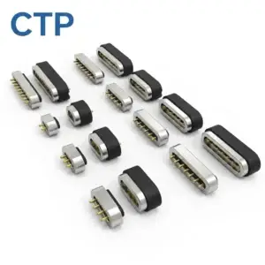
CTP’s compact magnetic connector designs offer several ways to manage that space. A two-contact DC pair serves a focused power connection. FPC modules move the connection towards a board elsewhere in the enclosure. A right-angle termination changes the board approach, while a circular face provides another option for the outside opening. The benefit is a choice of installation routes, not just a choice of smaller-looking bodies.
A small DC pair for products with a simple power requirement
CTP-P4269 gives the team separate dimensions for both halves
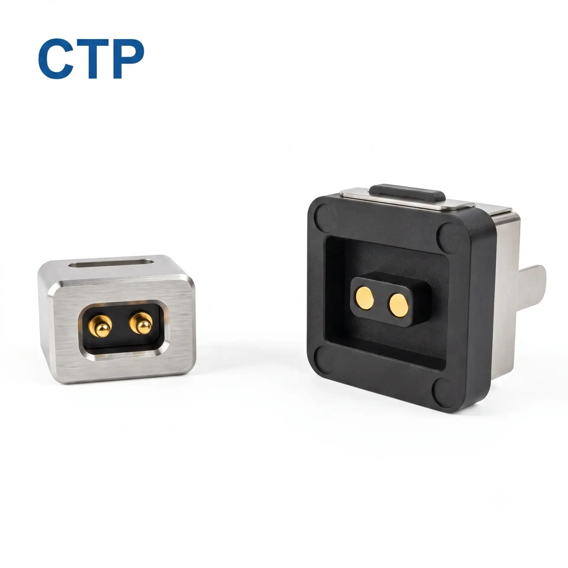
The CTP-P4269 has two contacts at a published 2.54 mm pitch. Its male reference dimensions are 9 × 6.5 × 7 mm, and the female outline reference is 12.1 × 11.6 mm. These dimensions give an enclosure designer a concrete starting point for the device side and the detachable head.
For a power-only accessory, the focused contact count has a clear purpose. Supply and return can be carried through one small mating pair without reserving positions for functions the device does not need. The team can then spend its packaging effort on the mounting, cable route and user grip rather than accommodating an unnecessarily broad contact array.
The two halves are considered in their actual mating relationship. Their component heights are not simply added to describe the installed assembly, because the geometry overlaps as they come together. Developing the pair in section lets the designer see where the useful space savings are, including how much of the removable head remains accessible outside the housing.
FPC modules free the space directly behind the magnetic face
One of the most useful ways to make a connection fit is to change where its termination goes. The contact face may need to sit on the product’s outer wall, while a battery or mounting boss occupies the area behind it. A flexible printed circuit provides a route from that face towards electronics elsewhere in the assembly.
Five contacts with a flexible connection to the board
The CTP-P3911 five-contact FPC module is an option for a defined combination of power and additional circuit functions. Its tail gives the mechanical team another route to the board, which can be especially useful in a handheld product where the external connection and main PCB cannot share the same location.
For example, a curved enclosure may place the mating face at an angle to the flat board inside. The flex can connect those regions while the carrier is supported at the housing. That lets the outside form follow the user’s grip and the board position follow the internal layout. The connector is helping the product fit together, rather than dictating where the main electronics must sit.
Seven contacts when more functions need the same compact route
The CTP-P3916 seven-contact FPC module provides more positions while retaining an FPC termination. It is useful to compare when a dock or accessory needs charging together with identification, detection or several control paths. The additional functions can be considered at one face instead of being added through another external connector.
The tail still needs real space for its bend and termination. That is an installation detail worth including early, because it protects the advantage the flex offers. A route that clears the enclosure seam and surrounding components allows the carrier to stay properly supported while the connection reaches the board. CTP’s two FPC formats give the team actual options to compare against that route.
A right-angle terminal can make a different PCB layout possible
An FPC is not the only way to change the internal connection direction. The CTP right-angle magnetic connector reference offers a board-oriented route with bent terminals. It is worth evaluating where a straight termination would place the board in an inconvenient position or consume depth the enclosure cannot spare.
The benefit is specific to the layout. Changing the terminal direction can help the connector meet a board arranged beside the interface instead of directly behind it. The PCB footprint, soldering access and support are developed from the selected drawing. This gives the product team another mechanical option without assuming every small device needs the same termination style.
It also brings assembly into the packaging discussion. The board has to be installed, connected and inspected, not merely represented by a thin line in a section drawing. The CTP PCB mounting guide covers related support and integration choices. Including that route while the enclosure is open to change is much easier than finding room for it after every nearby component has been fixed.
A round face for a compact opening on the outside
The CTP-MC-R10-3P-S01 three-contact round pair offers a different front-face shape. It can suit a product where a circular opening works well with the enclosure’s appearance and mounting area. The three positions provide a focused circuit arrangement to develop with that outside form.
For a small removable accessory, this creates another design direction alongside the DC pair and FPC modules. The circular face can be considered with the user’s access and the rear installation, including any feature needed to establish orientation. A compact opening is most useful when its internal mounting and termination fit just as comfortably.
Imagine a sensor housing with enough room around the front panel but little access behind it once the board is installed. The round connector may fit the opening, while the assembly sequence decides when it must be secured and connected. Considering the actual CTP pair early makes that sequence part of the selection, rather than leaving the mounting problem for the production team.
Which CTP format helps with your space constraint?
The smallest outside dimension is only one possible advantage. In some products, moving the termination saves more useful space than reducing the mating face. In others, a focused two-contact interface or a circular opening is the better starting point. This comparison shows how the different formats address different packaging needs.
| Space constraint | CTP option to explore | Practical advantage |
|---|---|---|
| A simple power connection with a small mating area | CTP-P4269 DC pair | Two contacts and dimensioned references for both sides |
| The main board cannot sit behind the contact face | CTP-P3911 or CTP-P3916 | A flexible route between the supported face and electronics |
| The PCB needs another approach direction | Right-angle magnetic connector reference | A different terminal direction for the board layout |
| A circular opening suits the enclosure | Round three-contact pair | A round mating format for a focused set of circuits |
Leave the spring contacts enough working room
The spring-loaded contact is part of the usefulness of a magnetic interface. Its movement provides contact pressure at the selected working compression, while the enclosure establishes the seated position. Keeping that relationship intact allows compact packaging to serve the electrical connection rather than merely reducing the visible outline.
In a thin product, moving the carrier inward changes the distance to its mating target unless the other side moves with it. The FPC may still reach the board perfectly, but the contact position has changed. This is why the installed section is so useful: it shows the space saving and the contact relationship in the same view.
CTP’s working-stroke guide explains the related seated geometry. The final dimensions, working range and electrical loading are established for the selected assembly. A compact product can then be evaluated with its normal support and termination, rather than relying on a loose component that has more freedom than it will have inside the enclosure.
Build the connection into the product layout
CTP supports connector components and custom magnetic assemblies, giving the project room to choose how much of the connection is integrated in-house. For the compact interface, the useful conversation begins with the restricted space: where the face belongs, where the board sits and what must remain clear for assembly and removal.
The small DC pair, FPC modules, right-angle route and round face each answer that brief in a different way. They also leave room to consider the required circuit functions before the enclosure is committed. The choice is easier to make when the comparison is between complete installation routes rather than isolated product dimensions.
For your next compact device, bring the connector into the layout while those routes are still available. A useful magnetic interface fits with its mating half, support and termination, and remains comfortable to connect after the cover is closed. That is the space saving these CTP formats are there to help you develop.