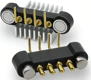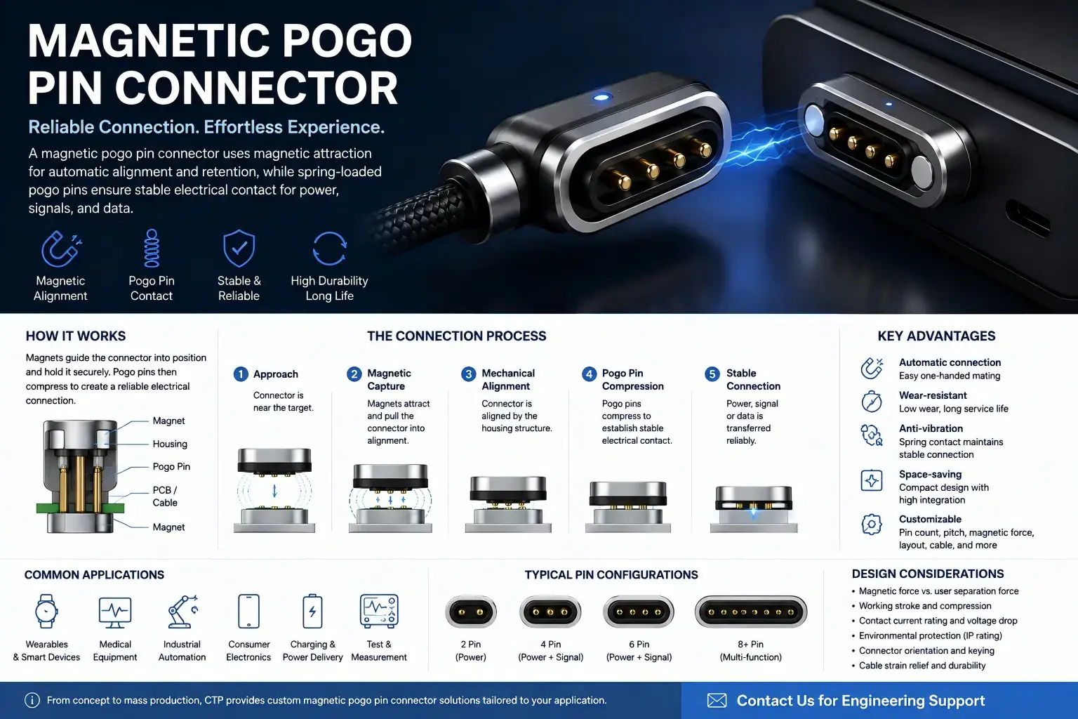
A magnetic pogo pin connector should be designed from the final assembled product geometry, not from connector travel or magnetic force in isolation. The housing, PCB, mating target, mechanical stop, connector mounting datum and magnets all contribute to the installed interface condition.
This matters because the same dimensional stack-up determines several things at once: pogo-pin compression, magnetic air gap, spring reaction, final seating position and contact alignment. A connector can perform correctly on a bench fixture yet move outside its intended operating window after enclosure tolerances, PCB position and production variation are added.
The practical design rule is simple:
Working stroke is an installed product condition. Magnetic capture is not the same as controlled final seating.
What Actually Defines a Magnetic Pogo Pin Connector’s Installed Condition?
A magnetic pogo pin connector combines several mechanical and electrical functions, but those functions should not be assigned to the same component.
| Function | Primary Design Element |
|---|---|
| Initial capture | Magnetic system |
| Final lateral and angular positioning | Housing guides, keys and mechanical datums |
| Final seated Z position | Mechanical stop and product stack-up |
| Local contact compliance | Spring-loaded pogo pins |
| Electrical transfer | Pogo contacts, target surfaces, terminations and conductors |
| Connection-state control | System electronics where required |
The magnet can attract the two halves and contribute to retention, but it should not be expected to define precision final position by itself.
Likewise, the pogo pins should provide controlled Z-axis compliance rather than act as the structural stop for the complete assembly.
A robust design therefore follows this sequence:
Magnetic capture → mechanical guidance → final datum → controlled pogo compression → electrical contact.
Why Connector Travel Alone Cannot Define Working Stroke
Total pogo-pin travel describes how far the plunger can theoretically move between its mechanical limits. Working stroke describes the compression range approved for the installed connector condition.
They are not the same parameter.
A useful simplified relationship is:
Installed compression = free contact height − seated contact gap
The seated contact gap is not controlled by the pogo pin alone. It is produced by the complete mechanical assembly.
Depending on the architecture, contributing dimensions may include:
- connector mounting height;
- PCB thickness and position;
- enclosure datum position;
- target-pad height;
- mating housing dimensions;
- mechanical-stop position;
- adhesive or gasket thickness;
- connector insert position;
- assembly tolerance;
- structural deflection.
If a design uses total travel as the working-stroke target, it can accidentally leave too little operating margin for production tolerance, wear or external disturbance.
Build the Datum Chain Before Calculating Compression
Before calculating pogo-pin compression, define which physical surfaces control the final position of the two mating assemblies.
A typical datum chain might look like this:
Device enclosure datum → connector mounting datum → mechanical stop → mating housing datum → target-contact plane
The actual chain will differ by product, but every dimension that affects final contact separation should be visible in the mechanical analysis.
Why the Mechanical Stop Matters
The mechanical stop determines when the two product halves stop moving toward one another.
If the pogo pins become the effective stop, additional closing force can be transferred into the spring contacts, PCB, target surface or solder joints.
This can produce a failure chain such as:
Incorrect stop position → excessive pogo compression → higher spring reaction → increased structural load → reduced mechanical margin.
The mechanical structure should therefore define the final seating position, while the pogo contacts accommodate the remaining dimensional variation inside the approved working window.
Calculate Minimum, Nominal and Maximum Installed Compression
A nominal CAD dimension is not enough.
The design should evaluate at least three assembled conditions:
- minimum compression;
- nominal compression;
- maximum compression.
The minimum-compression condition identifies whether tolerance can leave the contact too lightly compressed.
The maximum-compression condition identifies whether the stack-up can drive the contact too far into its available operating range or impose excessive mechanical reaction.
The nominal condition provides the intended center point but should not be used as a substitute for corner analysis.
Minimum Compression
Minimum installed compression typically occurs when dimensions combine to create the largest seated separation between the pogo mounting datum and the mating target.
Possible consequences include:
- reduced contact-force margin;
- greater sensitivity to vibration or movement;
- higher sensitivity to contamination;
- intermittent electrical contact;
- increased resistance variation.
Maximum Compression
Maximum compression occurs when the tolerance stack creates the smallest seated separation.
Possible consequences include:
- higher pogo spring reaction;
- greater load on the target surface;
- more load transferred into the connector housing or PCB;
- reduced tolerance for additional deflection;
- changes in the force balance that retains the mating interface.
The objective is not maximum compression. The objective is a controlled operating window across the complete assembly distribution.
Magnetic Air Gap and Pogo Spring Reaction Are Coupled
The magnetic and spring systems should not be analyzed independently.
As the mating halves approach one another, magnetic attraction changes with the magnetic circuit and separation geometry. At the same time, the pogo pins begin compressing and generating an opposing spring reaction.
A useful conceptual bookkeeping model is:
Available retention margin ≈ magnetic attraction − pogo spring reaction − other separating loads
This is not a universal magnetic-force equation. Actual attraction depends on magnet geometry, material, polarity arrangement, surrounding ferromagnetic structure, air gap and lateral position.
Other separating loads can include:
- gasket compression;
- cable load;
- housing deflection;
- vibration;
- external peel force;
- product weight or acceleration.
This creates an important coupling.
If the tolerance stack increases the magnetic air gap while also increasing pogo compression, magnetic attraction may decrease while spring reaction increases.
That combination can reduce seated retention margin even though neither the magnet nor the pogo pin has changed as an individual component.
This is why the connector should be evaluated as a complete assembled interface.
How Lateral Offset and Tilt Change the Contact Condition
Z-axis compression is only one part of tolerance engineering.
A magnetic interface also has to manage lateral offset, angular error and housing tilt.
The magnet may assist gross capture, but final alignment should come from mechanical geometry where precise contact location is required.
Consider an interface that approaches at an angle.
One side may contact first, compressing some pogo pins before others.
The resulting chain can be:
Angular error → uneven first contact → asymmetric pogo compression → tilted seating → uneven force and electrical contact conditions.
Similarly:
Lateral offset → partial target overlap → side loading or incorrect contact location → contact instability or mechanical wear.
For multi-pin structures, the mechanical team should review the complete contact array rather than only the centerline of the connector.
How Stack-Up Errors Become Electrical Problems
Tolerance analysis may begin as a mechanical task, but the final consequences often appear electrically.
A simplified contact path can be represented as:
Source → termination → pogo contact → mating interface → target → device conductor → load
If the installed geometry reduces the stability of the contact interface, resistance may vary.
That variation can contribute to voltage drop, local power loss or intermittent operation depending on the circuit and load.
The basic relationships remain:
Vdrop = I × Rpath
Ploss = I² × Rpath
The purpose of these equations is not to assign a universal resistance or current rating to a magnetic pogo pin connector. They show why a mechanically unstable contact condition can become an electrical or thermal problem.
A useful cause-and-effect chain is:
Under-compression → less stable contact condition → resistance variation → voltage disturbance or additional local loss.
Another is:
Contamination → incomplete seating → reduced working stroke → unstable contact → intermittent function.
Why Prototype Success does not ensure Production Robustness
Prototype hardware often represents only a small portion of the dimensional distribution that will exist in mass production.
A hand-assembled prototype may also receive extra adjustment that production units will not.
Production variation can enter through:
- molded enclosure dimensions;
- PCB fabrication and assembly;
- connector placement;
- solder-joint geometry;
- adhesive thickness;
- insert molding;
- magnet installation position;
- mechanical-stop dimensions;
- mating-target flatness;
- fixture and assembly variation.
This leads to a common development error:
Nominal prototype passes → tolerance corners are not evaluated → production units reach lower or higher compression → field behavior becomes inconsistent.
The correct response is not simply to increase magnetic force or select a pogo pin with more total travel.
The stack-up should first be corrected so the product has a defensible operating window.
Common Tolerance-Related Failure Modes
| Failure Mode | Possible Cause | Engineering Check |
|---|---|---|
| Under-compression | Maximum seated gap exceeds the intended contact condition | Calculate minimum installed compression |
| Over-compression | Minimum seated gap drives excessive plunger movement | Calculate maximum installed compression |
| Incomplete seating | Housing interference, contamination or force imbalance | Inspect mechanical stop and final gap |
| Asymmetric contact | Tilt or angular tolerance | Measure compression across the entire contact array |
| Reduced retention margin | Air gap, spring reaction or external load changes | Measure separating behavior at tolerance corners |
| Intermittent electrical contact | Low compression, movement, contamination or poor target overlap | Monitor continuity or resistance under representative disturbance |
| Target or housing damage | Excessive compression or poor mechanical stop control | Inspect contact surfaces and structural load path |
| PCB or solder-joint stress | Mating force bypasses structural support | Review the mechanical load path into the PCB assembly |
How to Validate the Complete Magnetic Pogo Pin Interface
A useful validation structure is:
Requirement → Test Condition → Measurement → Acceptance Criterion → Post-Test Check
The important point is to test the connector in representative assembled conditions rather than only as an isolated component.
| Requirement | Condition | Measurement |
|---|---|---|
| Working-stroke margin | Minimum, nominal and maximum stack-up | Installed compression |
| Correct final seating | Representative assembly tolerances | Stop position, gap and target alignment |
| Retention behavior | Relevant air gap and separation direction | Engaging / separating behavior |
| Electrical stability | Defined compression and mated state | Contact or complete-path resistance |
| Dynamic robustness | Representative motion, vibration or cable load | Contact disturbance or resistance variation |
| Lifecycle stability | Project-defined mating duty | Mechanical and electrical drift |
IEC 60512 provides standardized connector test methods that can support this process. Relevant methods include contact-resistance measurement, contact-resistance variation under dynamic conditions, engaging and separating forces, and connector mechanical-operation endurance.
These standards provide test methods rather than a universal acceptance limit for every magnetic pogo pin connector. The project specification still needs to define the actual sample configuration, tolerance condition, electrical load, environmental severity and acceptance criteria.
For a broader DVP&R structure, continue to CTP’s magnetic pogo pin connector validation guide.
When Magnetic Retention May Not Be the Right Architecture
A magnetic pogo pin interface is useful when removable mating, low insertion effort, blind capture, docking or controlled breakaway creates real product value.
Another connector architecture may be more appropriate when:
- a positive mechanical lock must withstand substantial sustained external load;
- precise final alignment cannot be established with the available mechanical package;
- ferromagnetic contamination cannot be controlled;
- a standardized connector already satisfies the required mechanical and electrical interface;
- the connection is effectively permanent;
- magnetic capture provides little functional benefit;
- the required mating state cannot be made electrically safe or mechanically repeatable.
The architecture decision should therefore begin with the interface duty rather than with magnetic attraction itself.
What to Provide for an Engineering Review
For a magnetic pogo pin connector tolerance review, the most useful inputs are:
- connector and mating-side 2D or 3D geometry;
- product datum scheme;
- pogo free height and approved working range;
- nominal seated gap;
- mechanical-stop geometry;
- PCB and connector mounting method;
- mating target height and flatness requirements;
- expected X/Y/Z mating tolerance;
- angular tolerance;
- magnet position and intended retention behavior;
- Pin Map and electrical load;
- environmental exposure;
- expected mating duty.
Engineers who are still selecting the connector structure can start with the magnetic pogo pin connector selection catalog.
If the connector structure is selected but PCB integration is not complete, see the magnetic pogo pin connector PCB integration guide.
For broader prototype-to-production selection decisions, continue to How to Choose Magnetic Pogo Pin Connectors.
Frequently Asked Questions
What is a magnetic pogo pin connector?
A magnetic pogo pin connector is a removable electrical interface that combines magnetic capture or retention with spring-loaded conductive contacts. Mechanical guides and datums should control final position, while the pogo pins provide local contact compliance.
What determines pogo pin working stroke in a magnetic connector?
The installed working stroke is determined by the complete assembled geometry between the pogo mounting datum and the mating target. Connector free height alone does not define the final compression.
Is total pogo pin travel the same as working stroke?
No. Total travel is the available mechanical movement of the contact. Working stroke is the approved compression range used in the final assembled product.
Should magnets define the final connector position?
Magnets can assist capture and retention, but precision final position should generally be controlled by mechanical datums, guides and stops where contact alignment and compression matter.
Can stronger magnets compensate for poor tolerance stack-up?
Not reliably. Increasing magnetic attraction does not correct an incorrect mechanical stop, excessive or insufficient pogo compression, target misalignment or housing interference.
Why can a magnetic pogo pin connector work in a prototype but fail in production?
A prototype may represent only nominal geometry. Production introduces dimensional and assembly variation that can change working stroke, magnetic air gap, target alignment and structural load.
How should minimum and maximum compression be evaluated?
Build the full dimensional chain between the connector mounting datum and the mating target, then evaluate the tolerance combinations that produce the largest and smallest seated gaps.
Does magnetic force determine electrical contact force?
Not directly. Local contact force is generated by the pogo spring at the installed compression. Magnetic attraction influences closure and retention of the complete interface, so both systems interact but perform different functions.
How should a magnetic pogo pin connector be validated?
Validate representative minimum, nominal and maximum assembled conditions for seating, compression, alignment, retention, electrical resistance, dynamic stability and project-specific lifecycle requirements.
Can a magnetic pogo pin connector transmit power and signals?
It can be designed with contacts assigned to power, ground, detection, control or signal functions. Actual capability depends on the complete Pin Map, electrical path, PCB or cable architecture and application requirements.
Request a Magnetic Pogo Pin Interface Review
If your connector has already been selected but the final working stroke or mating tolerance is still uncertain, provide the connector drawing, enclosure stack-up, mechanical-stop geometry, target position, PCB structure, X/Y/Z tolerance and available 2D or 3D files.
Submit Your Magnetic Pogo Pin Connector Project for Engineering Review
CTP ENGINEERING PATHS
Choose the right path for your project
Move from application requirements to a connector pair, a data-capable cable assembly, or a charging cable configuration. Final specifications are confirmed against an approved drawing and project validation plan.
Magnetic Connectors
Connector geometry, pin layout, mechanical integration and OEM/ODM review.
Engineering overview → 02Magnetic Data Cables
Power and signal allocation, cable exit, interface selection and assembly review.
Cable engineering → 03Magnetic Charging Cables
Browse the complete cable catalog and shortlist a starting structure for customization.
View cable catalog →