A small metal tip is where your product’s two halves finally meet. Its shape, the target beneath it and the direction of the connection all affect whether the interface fits the device naturally. Pogo pin tip selection is most useful when it begins with that real contact surface.
Our range includes rounded double-ended contacts, straight through-hole pins, individual SMT contacts and bent-tail designs. They offer different ways to reach a mating pad and connect it to the electronics. The aim is a contact arrangement that fits the product’s shape and normal handling, with the spring pressure defined for that arrangement.
Rounded contact ends can suit facing target surfaces
The CTP rounded-tip double-ended pogo pin, CTP-PP-1P-DE-A03, has rounded contact geometry at both ends of a straight cylindrical body. It is a two-sided format for connecting facing conductive surfaces within a compression assembly.
A rounded double-ended tip keeps both contact faces in view
This design is worth exploring for a removable module that needs an electrical bridge to the main device. Both ends have a defined place in the connection, so the carrier and the two target surfaces can be developed together. One contact component forms one electrical path between those surfaces.
The visible rounded profile gives the designer a clear starting geometry to compare with the mating pads. It does not require a sharp point to look purposeful. For a product with smooth contact targets, the choice can focus on a suitable contact area, the intended pressure and the way the two parts come together.
For example, a small sensor module might sit inside a molded carrier above the main board. A two-sided contact can be evaluated as part of that separable arrangement. The surrounding structure establishes the module’s position while the contact bridges the two conductive surfaces.
Pogo pin tip selection also includes the route behind the tip
The same target may be reached through different mounting formats. A straight-tail pin suits one board arrangement; a surface-mount base suits another. Comparing the complete contact helps you choose a part that works at both the visible interface and the connection inside the device.
Our through-hole spring-loaded pogo pin, CTP-PP-TH-A01, combines a moving plunger, cylindrical body and straight PCB tail. It provides an individual contact point for a layout built around through-hole integration.
The straight mounting tail can follow a through-hole PCB layout
For a charging cradle with room below its board, that format can give the contact a direct route into the electronics. Individual pins can be spaced to match the device’s target pads, including a layout that does not suit a fixed connector block.
That freedom is useful when a housing feature separates the contact positions. You can arrange the electrical points around the product rather than opening up a larger area simply to fit one standard block. The board and housing still establish the final installed relationship.
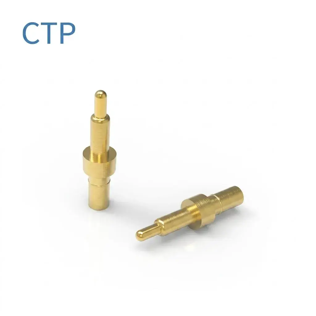
The CTP single SMT/SMD contact, CTP-PP-1P-A01, offers a surface-mount alternative. It is useful when the board layout calls for an individual contact without a through-hole tail. The contact positions can still follow the target arrangement required by the product.
A side-facing connection needs a suitable termination shape
A device is not always connected from above. An accessory may approach from the side of a desktop instrument, or a compact housing may leave little room behind the mating face. Our right-angle pogo pin with a bent tail, CTP-PP-1P-RA-HC-A01, gives the designer another route into that space.
The bent tail redirects the termination relative to the contact axis. That can help a side-facing contact meet a board lying in a different direction. It lets the interface location reflect how the product is used, while the termination reflects the space inside.
Imagine a handheld accessory connecting to the edge of a small base station. A contact at the side may be easier to reach than one hidden underneath. A suitable bent-tail geometry can support that arrangement without expecting the plunger to move sideways or act as a guide.
The housing guides the target toward the contact axis
The spring plunger provides movement along its axis. The enclosure or accessory guides the mating part toward it. Keeping those functions separate allows the contact tip to meet its target in the intended way, while the user experiences a connection shaped by the product.
This is why tip selection is easier with a view of the mating action. A photograph of a loose pin cannot show whether the accessory slides across the target, approaches straight on or settles into a pocket. The complete device view makes the useful contact options much easier to recognize.
A longer contact end can reach a recessed surface
Our long-plunger double-ended contact, CTP-PP-1P-DE-A02, uses different visible reach on its two sides. It gives a product with unequal interface depths another geometry to consider.
For a removable module with a target set back inside its housing, that extra reach may help the connection follow the module’s existing shape. The opposite side can meet a shallower target near the board. The exact installed dimensions and available movement are defined for the selected part.
The benefit is having more than one two-sided contact profile available. A rounded symmetrical-looking format and an extended-end format serve different packaging conversations. You can compare them with the target locations rather than choosing a contact solely from its overall length.
This can be especially helpful while a product is still taking shape. The contact choice can develop with the housing recess and carrier, instead of requiring a deeper redesign after the target locations are fixed.
A good contact face works with the pad you actually have
Individual contacts are useful when the target pattern is unusual. A small accessory might have pads on either side of a locating feature, leaving no convenient space for a rectangular connector body. A pair of separately positioned SMT or through-hole pins can follow that arrangement. The choice of mounting style then reflects the board beneath the targets.
A removable module with two facing target planes presents a different opportunity. The double-ended formats let the designer consider a compression connection through the carrier itself. The rounded-end version has a straightforward two-sided profile, while the extended-plunger version offers unequal reach. Those are concrete differences in the components available, rather than a generic claim that one tip is best.
The side-facing contact adds another option for a product used on a desktop. If the user naturally brings the accessory toward the front of the instrument, placing the contact at that edge can feel more convenient than requiring the instrument to be lifted. The bent termination can then connect that face to the board inside.
For a product maker, the advantage of this range is being able to compare the contact shape with the actual target and handling direction. You can retain the device’s useful layout and choose a suitable electrical contact around it. The visible tip, mounting base and termination all contribute to that fit.
The mating target’s material, finish and usable area belong in the discussion. A smooth device pad, a recessed target and a board test point are different surfaces. The contact tip should be considered for the one your product actually uses.
The target area also affects the room available for normal alignment variation. If a pad sits very close to its neighbor, a contact that looks appropriate in isolation may be less convenient within the complete layout. Choosing the tip and target together gives the design a more useful basis.
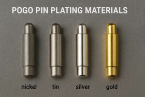
Our pogo pin materials guide explains more about contact construction and finishes. Those details help refine the choice, particularly for a product that will be connected and removed regularly.
Does a sharper tip automatically make a better connection?
No. The useful tip depends on the intended target and operating condition. A point that seems attractive for penetrating a surface may be unsuitable for a finished device pad. Our listed rounded contacts should be evaluated on their own geometry, with the pressure and mating action appropriate to the product.
Can the same contact suit every removable accessory?
A similar-looking interface can hide different board positions, recess depths and target finishes. Our SMT, through-hole, bent-tail and double-ended formats provide starting points for those different arrangements. The selected configuration is matched to the device rather than treated as a universal replacement.
A well-chosen pogo contact is easy to overlook in daily use because it fits naturally into the connection. The target is accessible, the mounting style suits the electronics and the spring has the movement it needs. That is the value of choosing the whole contact around your product, from its small mating tip to the termination behind it.