You notice the feel of a magnetic connector every time you use it. The head should stay comfortably attached during the movements the product is designed for, then come away in the way the user expects. A connection that feels secure but awkward to remove is a different product experience from one that releases with a deliberate, comfortable action.
CTP develops magnetic connector components and cable assemblies around that interaction. Magnetic connector pull force is considered with the mating shape, installed gap, contact pressure and cable route. Our round pairs, ring-type interfaces, FPC modules and finished leads provide several starting points for finding a useful balance between retention and convenient removal.
A useful magnetic connection has to feel right in the device
For a desk charging lead, the product brief may call for the head to remain seated while the cable is moved normally across the desk. A handheld accessory may need a grip that lets the user remove it easily. A docking interface may have a different removal direction again. Those everyday actions give the retention requirement its real purpose.
The advantage of a custom discussion is being able to consider them before choosing a force value. The head, enclosure and lead work together when a pull reaches the connection. A magnetic component selected in isolation may be held quite differently after installation, so the product’s intended interaction belongs at the centre of the choice.
This also lets the team distinguish two useful qualities: a positive seated feel and a convenient release action. They do not always call for the same movement. A head can resist a straight pull yet be easier to lift from one edge. Whether that is desirable depends on how the accessory is meant to be handled.
Round CTP pairs offer different starting structures
A three-contact pair for a focused accessory
The CTP-MC-R10-3P-S01 round three-contact pair combines a circular mating format with three electrical positions. It is worth considering for a compact accessory whose circuit needs that allocation. The circular body gives the design a specific face and mounting relationship to work with when shaping the attachment and removal experience.
For the user, the visible head and the room around it affect how the pull is applied. A head that is accessible at the edge can be removed differently from one recessed into a panel. Developing the CTP pair with that surrounding geometry helps the product team give the accessory an intentional grip, rather than leaving removal to whatever movement the user discovers.
Five contacts for a broader round interface
The CTP-MPC-5P-RD-HT-A01 five-contact round pair provides another layout when the accessory needs more electrical paths. It can be considered with power, control and identification requirements at one circular face. The matching spring-contact and target halves form the basis for developing the complete installed connection.
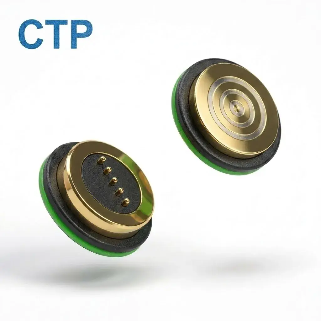
Contact count alone does not decide how firmly either round pair holds. The magnets, gap, compressed contacts and housing contribute to the result. The two formats offer different electrical and mechanical arrangements to work with. The circuit and the required handling action guide the selection together, with retention evaluated for the installed pair.
A ring-type pair adds another mating geometry to the choice
The CTP four-contact ring pair offers a different contact-and-target arrangement. It gives the project another structure to evaluate when the interface needs a particular face shape and circuit allocation. Its mounting and the accessible part of the removable head are considered with the way the product will be disconnected.
Think of a small accessory used several times a day. A convenient head gives the fingers somewhere to act and lets the cable leave without obstructing that grip. These details can be just as noticeable to the user as the initial magnetic attraction. The connector’s product value comes from how the entire interaction is developed, rather than from seeking the largest possible force figure.
For a product intended to release during a defined snag, that action becomes a separate requirement. The direction and electrical behaviour need to be established for the complete device. Magnetic attachment provides a way to develop a removable coupling; it is not a blanket promise that every accidental pull will protect the equipment.
The cable is part of the pull-force design
A finished lead lets the magnetic head and cable exit be considered together
CTP’s sixteen-contact circular cable-and-receptacle assembly brings the head, conductors and matching device-side interface into one assembly discussion. This is useful where the lead carries several project-defined power and signal functions and its route has a meaningful effect on how the connector is loaded.
The cable may reach around a stand, leave a handheld device beside the user’s grip or run towards equipment behind a desk. Its length, bend and overmould determine how those movements reach the magnetic head. Considering the finished lead gives the project a more useful basis for discussing retention than pulling a bare head with the cable omitted.
A cable pressed against an enclosure edge can apply a lifting action at one side of the interface. A freer route may allow the head to remain evenly seated during normal movement. CTP’s cable assembly scope allows these routing requirements to be considered alongside the magnetic connection and opposite-end termination, rather than left outside the connector brief.
The cable-exit and strain-relief guide explains the related installation choices. For a product team, the benefit is a coordinated accessory: the lead reaches where it needs to go, and its first bend supports the intended use of the magnetic head.
FPC modules combine contact functions with another internal route
On the CTP-P3916 seven-contact FPC module, the installed carrier support helps determine what moves when the mate is pulled. Securing the carrier at the housing and routing the flex towards the board allows the retention discussion to focus on the mating pair, rather than an unwanted movement of the module inside the device.
The supported carrier and compressed contacts form part of the seated arrangement. Spring contacts provide electrical contact pressure at their working position; the magnetic structure contributes to holding the mating halves together. Keeping those roles in view helps the product team develop the connection as a complete interface, with the flex carrying circuits rather than locating the face.
A controlled tail route is especially valuable in a compact dock. It connects the interface to the electronics without needing to pull the carrier to one side. The installed support, contact movement and any sealing feature are then considered with the desired retention. CTP’s FPC format offers routing freedom while leaving the face position to the surrounding mechanical design.
What a magnetic connector pull-force figure should represent
A clear force requirement makes the development conversation easier. It describes how the part is held, where the pull is applied and what action the user performs. A straight separation measurement and a cable-induced peel answer different questions, even when both are useful for the same accessory.
There is no single force value that applies to every round pair, ring interface or FPC installation. The selected CTP assembly is evaluated in the required configuration. This keeps a product claim connected to its actual use and leaves room to tune the structure around the desired handling experience.
For example, a desktop lead can be assessed with its normal route and a deliberate removal grip. A handheld accessory can be considered with the device in the user’s hand. These approaches make the requirement easier to relate to the product, rather than asking the buyer to interpret a catalogue number without knowing the movement behind it.
Develop the attachment and release as one user action
Start with the electrical format that suits the device: a focused round pair, a ring-type arrangement, a seven-contact FPC module or a broader finished cable. Then develop the mounting and removal route around the way the accessory is used. The CTP contact-force guide provides more detail on the spring-contact side of that relationship.
For an OEM, the value of the CTP range is having both component and assembly routes available. You can keep integration within your device build or discuss a finished lead whose cable exit and termination are developed with the magnetic head. That makes retention a product feature to shape, rather than a number that arrives after the design is fixed.
When you handle the next sample, try the movement the user will actually make. The right outcome is a connection that remains seated during its intended use and releases through the agreed action without an awkward grip. A suitable CTP format, developed with the enclosure and cable, gives the project a practical route towards that feel.