01
Pin Map and Contact Functions
Define the function of each power, return, signal, control or detection contact.
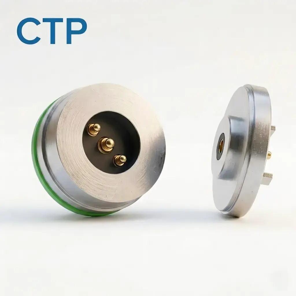
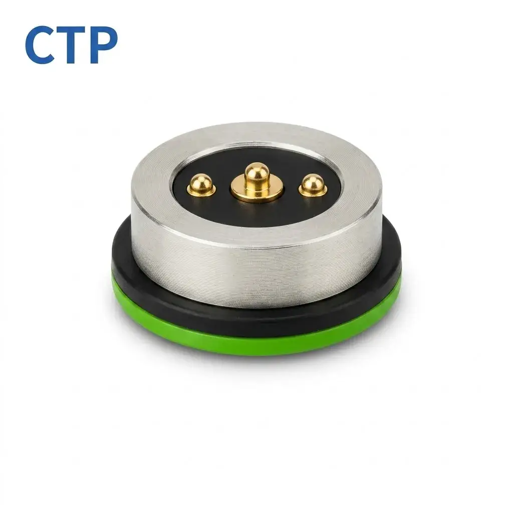
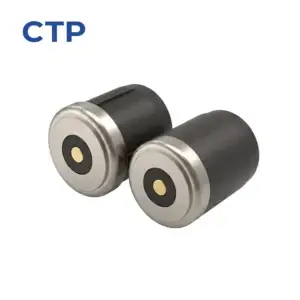
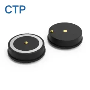
The CTP 3 pin round magnetic pogo pin connector is a customizable interconnect for electronic devices requiring quick alignment and repeatable mating. Its circular magnetic interface guides the two connector halves into position, while the three contacts can be assigned according to the electrical requirements of the project. Connector dimensions, pin definition, contact height, magnetic force, mounting structure and termination can be reviewed and customized to match the device design.
Product specifications should be reviewed together with the customer device, PCB, electrical assignment and mechanical mating conditions.
Define the function of each power, return, signal, control or detection contact.
Provide voltage, continuous current, peak current and required signal conditions.
Provide available length, width, height, PCB area and required mating orientation.
Provide application, expected quantity, environment and customer validation requirements.
Review the product-specific description, technical parameters, contact arrangement, mechanical structure and project conditions below.
The CTP 3 pin round magnetic pogo pin connector is a customizable interconnect designed for electronic devices that require a circular mating interface, quick alignment and convenient repeated connection. The magnetic structure helps guide the two connector halves into position, while the spring-loaded contacts maintain electrical contact after mating.
This connector uses a three-contact arrangement. The function of each contact is not fixed and should be defined according to the device circuit, operating requirements and mating structure. It can be evaluated for customized power, charging, detection or signal connections after engineering review.
| Item | Product Information |
|---|---|
| Product Type | Magnetic Pogo Pin Connector |
| Contact Count | 3 Pin |
| Connector Shape | Round |
| Mating Method | Magnetic mating structure |
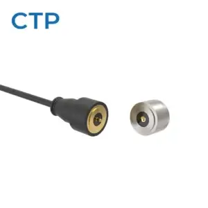
| Connector Configuration | Pogo pin side and mating contact side |
| Pin Assignment | Defined according to the customer circuit |
| Product Development | Custom engineering review available |
The connector can be reviewed according to the available installation space, electrical requirements and mechanical mating conditions of the device. Custom development may include:
This 3 pin round magnetic connector can be evaluated for customized electronic devices that require a compact circular interface, frequent mating or simplified user connection. The final application suitability depends on the required current, voltage, signal type, installation space and operating environment.
To evaluate whether this connector is suitable for your project, please provide the pin function, operating voltage and current, available installation space, PCB or wire connection method, mating orientation, environmental requirements, expected quantity and any available 2D or 3D drawings.
It is a circular magnetic interconnect that uses three electrical contacts and a magnetic mating structure to connect two parts of an electronic device.
No. The function of each contact should be assigned according to the customer circuit and may be used for power, charging, detection or signal requirements after engineering evaluation.
Yes. The connector dimensions, contact arrangement, magnetic structure, mounting method and termination can be reviewed according to the device design.
This product page presents a CTP magnetic connector configuration for engineering reference. Final dimensions, electrical ratings, materials, magnet structure, sealing level and reliability targets are not universal values; they are confirmed against the approved drawing, installation condition and model-specific validation plan.
CTP reviews the application and prepares a drawing or specification for approval before sample production. Test scope, acceptance criteria and report format should identify the model, sample status, method, conditions, result and review date.
Yes. Customization can cover geometry, contact layout, materials, cable construction, magnetic structure, sealing and appearance. Feasibility depends on the application and approved specification.
No. Current, voltage, resistance, temperature rise and ingress-protection claims apply only to the identified model and stated test conditions.
Timing is confirmed after the drawing, materials, tooling, sample quantity, validation scope and production requirements have been reviewed.
ENGINEERING CONFIRMATION BEFORE SAMPLING
Confirm power, signal and grounding allocation for the intended device.
Confirm working stroke, alignment, mounting, retention and mating behavior.
Confirm cable exit, host interface and project-specific assembly requirements.
Use the approved drawing and agreed validation plan as the release reference.
Submit your Pin Map, electrical requirements, available space, mating structure and project quantity for connector selection or custom development review.
Use the following engineering guides to compare contact count, contact allocation and connector layout before confirming the final product or customized design.
Review the complete selection path from contact count and electrical functions to connector shape.
View Main Guide →Compare one-contact special structures, complete two-contact circuits and third-contact functions.
Compare Low-Pin Designs →Determine whether four contacts are sufficient or whether a defined fifth electrical path is required.
Compare 4 Pin and 5 Pin →Calculate the contact budget and compare six-contact, multi-row and customized contact-array structures.
Compare High-Pin Designs →