A dock can do more than supply power. It can recognise an accessory, identify the version attached and let the device begin the right function once the connection is ready. For an equipment brand, those details make the dock a more useful part of the product rather than just a place to charge it.
CTP’s multi-contact magnetic connectors provide electrical paths for that kind of development. Magnetic connector mating detection is designed with the device electronics, while the connector, FPC or finished cable carries the required connections. Our five- and seven-contact modules, configurable dual-row series and custom cable assemblies give the project several ways to bring those functions into one convenient interface.
Give the magnetic interface a useful job beyond charging
A basic charging accessory has a clear task: connect a supply and return. A more capable dock may also need to know which device has arrived or whether an accessory is present. Those functions can improve how the finished equipment behaves, provided the interface has the right paths between the accessory and the controller.
This is where a custom magnetic connection is valuable. The circuit allocation can follow the product’s functions instead of being limited to an unrelated cable pinout. The magnetic head provides the everyday attachment, while additional contacts carry the identification, detection or control paths chosen for the electronics.
For an instrument family, that might allow the host to distinguish two accessory types before enabling their respective functions. For a charging cradle, it may support a device-presence input alongside the power connection. These are possible application architectures, not electronics built into a bare CTP connector. The product range supplies the physical interface around which the system can be developed.
CTP FPC modules bring several functions to a small contact face
Five contacts for a focused accessory circuit
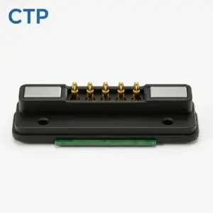
For an accessory-identification circuit, the extra contact needs to reach the controller that reads it. The CTP-P3911 five-contact FPC module provides five positions and a flex termination for carrying the selected power and sensing paths into the device. That gives the identification function a route through the interface, alongside the charging connection.
That combination helps a compact product in two ways. The contact count gives the circuit designer more allocation choices than a power-only pair. The FPC gives the mechanical designer another internal route. A device can therefore place its external connection where the user can reach it while arranging the controller board around the other components inside.
Seven contacts for identification, detection and other controls
If identification and seating detection need separate paths, the CTP-P3916 seven-contact FPC module gives the circuit two more positions to consider. The benefit is room to distinguish functions that provide different information to the host, while still carrying them through one removable interface. Their references and any remaining controls are included in the allocation.

For a dock supporting two versions of a handheld product, that extra room can be useful during planning. The team can consider what both versions need to exchange before committing to the interface. A common connector may be suitable if the circuit and mounting allow it, while the additional positions remain available for the functions that actually justify them.
Identification and seating detection can make different contributions
Accessory identification answers which item is connected. Seating detection answers whether a defined connection condition has been reached. Keeping those roles clear helps the electronics use the available contacts well. An identification response may select an operating mode, while another condition determines when the load can be enabled.
The benefit to the user can be a device that handles its accessories more intelligently. The host can be designed to recognise an expected accessory, stay inactive for an unrecognised one or respond when a lead is removed. The precise behaviour belongs to the product’s controller; the CTP interface gives the project a way to carry the necessary signals.
A sensing path also needs its reference connection. When allocating the five- or seven-contact FPC module, the power returns and signal references are considered alongside the extra inputs. That makes the connector discussion more useful than adding a contact labelled “detect” after all other positions have been assigned.
Magnetic sensing is another possible system approach. Texas Instruments’ Hall-sensing application brief describes a general relationship between magnetic sensing and power control. A nearby magnet and fully seated electrical contacts are different observations, so the selected sensor and controller are developed around the actual device geometry. CTP’s connector can be part of that system without being described as a sensor itself.
Choose a contact count within the dual-row family
The CTP 2–8 pin dual-row series offers several configurations for custom power and signal interfaces. This gives a team another route when the application needs a particular combination of circuit functions, housing form and environmental integration. The actual model is selected for that project rather than treated as one universal wiring arrangement.
A defined set of paths at one removable interface
A three-contact allocation might be considered for power, return and one additional function. A broader allocation can accommodate more identification, control or signal paths, depending on the circuit. The series lets those requirements be considered against a family of physical structures rather than forcing every accessory into the same contact count.
The contact insert, target half and housing also provide a basis for the mechanical development. The product team can work on the final seating arrangement while the electronics team develops the sensing paths. This matters because the usefulness of a detection signal depends on the connection it represents, not merely on having another wire available.
A finished magnetic cable can carry the control path too
The CTP four-contact magnetic cable with a USB-C opposite end brings the head, conductors and opposite-end connection into one assembly discussion. Its four magnetic paths can be assigned for the required project functions. One possible architecture combines power with identification or detection, where the host and device electronics support that arrangement.
For the OEM, the advantage is continuity of the design across the lead. The device-side contact is connected through the cable to the intended terminal, and the cable length and conductor choice are considered for the installation. The sensing function does not stop at the magnetic face and become an unresolved wiring task elsewhere in the accessory.
This is useful for an equipment lead that forms part of the supplied product. The magnetic attachment, internal wiring and opposite-end interface can be reviewed as one item. The USB-C shell alone does not promise a particular sensing or power-control function; the custom assembly and the electronics it connects establish those capabilities.
The CTP DC power-path guide covers the related power connection. When a device enables its load conditionally, the sensing paths and power paths need to serve the same operating requirement. Bringing them into one cable brief makes it easier to define the accessory the product actually needs.
When a simple power pair is still the right choice
Not every product needs extra detection contacts. The CTP-P4269 two-contact DC pair remains a useful option for a focused supply-and-return interface. Its two positions at 2.54 mm pitch provide a simpler electrical format when the device’s functions do not require additional paths at that connection.
If presence is sensed elsewhere in the product, a separate contact may add no useful information. If the controller needs a dedicated electrical input, a larger contact arrangement can be considered. CTP’s range gives the project room to make that choice deliberately, rather than adding complexity to every charging product or leaving a more capable accessory short of connections.
Develop the connector around the accessory behaviour you want
Begin with the user-visible result: a dock recognises its device, an accessory selects the right mode or the equipment responds appropriately when a lead is removed. The circuit team can translate that result into sensing and control paths. CTP’s modules and cable formats can then be considered for carrying those paths in the available space.
The fault-detection guide provides more background on the complete interface. Final detection logic, power-control behaviour and electrical performance are established for the selected hardware and product electronics. Keeping that scope clear allows the connector’s actual advantages to stand out: extra circuit options, useful termination routes and a convenient magnetic attachment.
A smarter accessory does not necessarily need a larger or more complicated exterior. With a suitable CTP contact arrangement, the additional functions can live behind one magnetic face. That lets the product remain straightforward to connect while giving its electronics more information to work with.