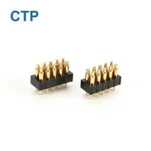
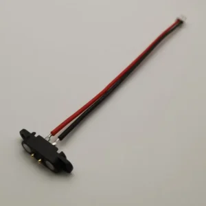
CTP’s multi-contact magnetic connectors give a power-and-control interface room to do more at one connection. Several positions can be allocated to supplies, returns and signals, with the physical format chosen for the device. For a removable module or custom dock, that is a useful alternative to adding separate connectors whenever the circuit gains another function.
Parallel power contacts are one possible configuration within that broader design. They allow more than one path to be considered for a supply or return, provided the complete electrical and thermal requirements are met. The CTP range includes a fourteen-contact pair, a seven-contact FPC module and finished multi-contact cables, giving an OEM several ways to explore that arrangement.
More contact positions create more power-layout options
A multi-contact interface is useful because the available positions can be assigned to the product’s actual circuit. Some may carry power, some provide return paths and others serve identification or control. Keeping those functions at one magnetic mating area can make the external connection easier for the user while giving the electronics a more flexible interface behind it.
In a suitable design, multiple paths can share a current load. That gives the circuit team another arrangement to assess rather than relying on a single contact for every part of the power route. The potential benefit depends on the resistance, compression and thermal surroundings of the complete paths, so the selected assembly is developed for the intended load.
Our magnetic connector range provides real structures for that discussion. The contact count alone is not the rating, but it does determine which allocations are physically possible. Starting with an appropriate multi-contact format leaves room to develop power, return and signal requirements together.
Fourteen positions in a compact two-row arrangement
CTP-MPC-14P-DR-A01 brings several paths to one mating face
The CTP-MPC-14P-DR-A01 is a fourteen-contact magnetic pair with a 7 × 2 arrangement. Its two rows provide a physical layout for an interface with several project-defined circuits. Power and return allocation can be considered alongside the control and signal paths rather than added after the face has already run out of positions.
For a removable equipment module, the practical benefit is concentration of the connection. The user attaches one mating pair, while several electrical functions pass through it. The elongated dual-row shape also gives the enclosure designer a different option from a circular connector, which can be useful where the mounting area is wider than it is tall.
The spring-contact and target halves are evaluated as a pair in the installed geometry. That makes it possible to discuss how the rows seat, where the power paths are placed and how their terminations reach the board. The product provides a starting structure for a coordinated interface, rather than requiring the team to assemble a contact pattern from unrelated components.
A seven-contact FPC module connects the face to electronics elsewhere
CTP-P3916 adds a flexible route behind the power interface
With the CTP-P3916 seven-contact FPC module, a proposed power allocation continues through the selected flexible circuit. The seven face positions provide room to discuss supplies, returns and other functions; the copper routes connect that allocation to the board. This makes the module a useful option when the power interface needs a flex route as well as several contacts.
For a thin handheld, that can make the difference between moving a large board and routing a flex around the internal layout. The circuit allocation and the physical path are considered together. If parallel power positions are proposed, the selected copper paths and their terminations form part of the electrical design, alongside the contacts themselves.
The advantage of the FPC format is therefore broader than contact count. It gives the product team another installation route while retaining room for several functions at the face. A power-and-control connection can be developed for the device’s internal arrangement, with the final loading agreed for the complete module and its intended use.
A finished magnetic cable keeps the power route in one supply scope
The CTP sixteen-contact circular cable-and-receptacle assembly offers a different route for a broader connection. Its magnetic head, matching receptacle and cable conductors are considered as an assembly for project-defined power and signal paths. This is useful when the external lead forms part of the product being supplied to the user.

The conductors matter as much as the positions at the head
When a power path continues through a cable, conductor length, gauge and termination affect its resistance. A coordinated cable brief brings those choices into the discussion at the same time as the magnetic head. The product can then be developed for the source-to-device route, rather than leaving the electrical path beyond the connector to an unrelated lead.
This is particularly useful when several power positions join within the assembly. The drawing can show whether they remain separate through the lead or combine into a common conductor. That gives the electronics and buying teams the same definition of the cable, including the parts of the route that carry the combined current.
The sixteen-contact format also leaves room to consider signals and controls in the same detachable connection. Its full data and power capabilities follow the selected channel and current-path validation. For the OEM, the benefit is a complete assembly approach that can address both the visible magnetic interface and the less visible wiring behind it.
What parallel power contacts add when the design supports them
With two equal-resistance paths between the same points, the current divides equally between them. Their combined resistance is lower than that of either path on its own. This explains the appeal of parallel contacts, but it also explains why the complete branches matter: unequal resistance produces unequal sharing.
The connector contact, mating target, PCB or FPC route, termination and any cable conductor contribute to that branch. The return route carries the same total circuit current and deserves the same attention. CTP’s multi-contact products provide allocation options; the project establishes which arrangement makes useful electrical and thermal sense.
Samtec’s power-interconnect guide illustrates why the number of loaded positions and thermal conditions affect per-contact ratings. Those figures belong to its products. The relevant principle for a CTP assembly is to consider simultaneous loading in the actual installation, rather than multiplying a single-contact value by the number of available positions.
The 2–8 pin family offers another configuration route
The CTP 2–8 pin dual-row series covers several contact-count options for custom interfaces. It can be considered where the project needs a particular combination of power, return, detection and control functions in a defined housing arrangement. The selected model and termination follow the device requirements.
This family is useful when the electrical allocation and enclosure are being developed together. The project can compare the actual contact arrangement with the available mounting area, supported compression and any sealing boundary. Parallel paths remain one possible allocation, not a fixed feature assigned to every model in the series.
For a compact dock, the appropriate choice might use fewer positions and a focused power-and-control circuit. A broader module may lead towards the fourteen-contact pair, while a finished equipment lead may benefit from the sixteen-contact assembly. Having those routes available lets the power requirement be considered in a useful mechanical context.
A two-contact pair still has a place in the range
The CTP-P4269 two-contact DC pair provides a supply-and-return starting structure at a published 2.54 mm pitch. Where that configuration covers the product’s needs, it can keep the interface focused and the circuit allocation simple. A multi-contact connector is valuable when its extra paths have a job to do.
For higher loading, the selected pair’s complete rating still governs the application. A two-contact supply-and-return connection does not contain an additional parallel path merely because both contacts carry current. CTP’s broader range gives the project another option when a different validated power arrangement is required.
Match the CTP format to the complete power connection
The most useful starting information is the operating load, available space and the other functions that must cross the interface. From there, the fourteen-contact pair, FPC module, configurable series or finished cable can be compared as real product choices. The thermal validation guide and DC power-path guide cover the related electrical considerations.
The selected assembly is evaluated for current sharing, voltage drop and thermal conditions, including any partial-connection state the device must handle. That establishes the supported configuration while keeping the development focused on the product’s needs. There is room to consider the power architecture without losing sight of the enclosure, mounting or cable route.
For a multi-function device, the real advantage is having those choices at one magnetic connection. CTP offers the contact formats and assembly routes; the project uses them to build a power interface that fits its circuits, installation and intended operation.