For a removable control accessory, attaching the head should be the easy part. The user makes one connection, and the product handles the power, references and signals behind it. A well-integrated interface allows that simple outside action to serve several electrical functions.
CTP’s multi-contact magnetic connectors give OEM teams a range of structures for developing that interaction. Magnetic connector contact sequencing is considered with the contact layout, seating movement and device electronics. This brings the connector into the accessory’s operating design early, while the contact format and internal layout are still open to change.
One mating action for a multi-function accessory
A detachable module may carry power, a circuit reference and several controls. Bringing those paths into one magnetic mating area makes the accessory more convenient to connect. The user does not need to handle each function separately, while the electrical team can give the paths distinct roles behind the same face.
The order in which those paths become usable is part of the device design. A reference may be needed before a signal is interpreted, and a load may be enabled only after the required connections are ready. The connector’s geometry and the controller’s actions work together to support that behaviour.
That is a useful custom-development opportunity. The contact count, physical positions and termination can be considered with the product’s operating needs while the enclosure is still being developed. CTP supplies several formats for this discussion, from a flex-connected face to a two-row pair or finished cable.
Seven FPC contacts connect the accessory to the main electronics
CTP-P3916 brings several circuit functions to the magnetic face
The seven positions on CTP-P3916 let the team assign the circuits involved in the required operating sequence. A return, a control input and a detection path can have distinct roles, with the flexible printed circuit carrying their connections towards the controller. The positions provide the interface; the selected geometry and electronics establish how it operates.
For a handheld device, this can simplify the layout around the interface. The carrier is supported where the accessory attaches, and the flex follows the internal route to the controller. The board can remain in a position that suits the battery and other components, while the connector is placed for convenient user access.
That physical separation also makes the system easier to think about. The housing establishes the final seat, the spring contacts operate at the selected compression and the electronics decide when the connected functions may run. Each part has a clear role, with the FPC linking the face to the circuit rather than determining its position by itself.
A custom interface can be discussed around its required connection order
Contact sequencing is not automatically supplied by having several contacts. A specific early-contact or late-break requirement is developed for the chosen geometry and circuit. This keeps the product brief focused on the behaviour that matters, such as establishing a reference before a control function is used.
What first-mate/last-break means for the design brief
Some connector systems use different contact heights to establish an order. Mill-Max’s first-mate/last-break catalogue examples show this as a defined feature of particular products. For a CTP project, a similar functional requirement is reviewed for feasibility with the selected interface; it is not assumed to be a standard feature of every listed model.
The commercial benefit of a custom discussion is that the requirement can be raised early. The product team can describe which path must be available and what action depends on it, while the connector structure and device electronics are considered together. That is more useful than choosing the final housing first and adding an unexplained sequencing note afterwards.
For an accessory that starts an active function after attachment, the controller may provide part of the sequence by waiting for the required conditions. The contact arrangement supplies the paths it needs. This leaves room for a practical system solution rather than expecting a mechanical contact alone to make every operating decision.
A configurable contact family for different accessory functions
The 2–8 pin series provides several allocation choices
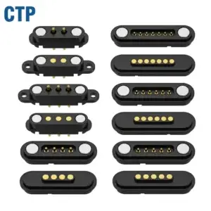
The CTP 2–8 pin dual-row series offers several contact-count configurations. Power, return, identification and project-specific signals can be discussed against the actual selected structure. Its spring-contact half, target half and housing provide the basis for developing a complete mating interface.
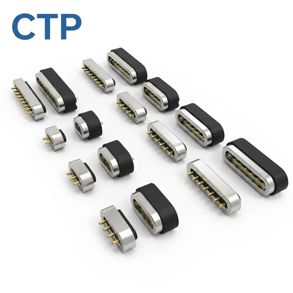
For a charging dock, the chosen allocation may be relatively focused. A removable control module may need more functions at the same boundary. The family lets the team consider those requirements without assuming that one contact count or one termination must suit every device.
The seating movement also belongs to that choice. The surrounding guides and stops establish how the selected pair reaches its operating position. Considering them with the contact pattern gives the electronics a physical interface to work with, helping the final product support its intended connection and removal actions.
Fourteen contacts for a broader removable module
The CTP-MPC-14P-DR-A01 uses fourteen contacts in two rows of seven. This format is useful where several power, reference and signal functions need to share one magnetic connection. Its elongated arrangement provides a different packaging option from the smaller FPC and circular formats.
For the person using the equipment, those functions can remain behind one attachment action. For the design team, the two rows provide actual positions to allocate and route. The required circuit relationships can be developed on that layout rather than represented only as a list of functions with no physical home.
Where order matters, the approach direction and selected contact positions are reviewed together. A module can arrive slightly angled before it reaches the final seat. The product’s required sequence is therefore established for the real movement and electronics, while the fourteen-contact pair provides the broader interface structure around which that work is done.
Finished cables and board terminations complete the connection
The CTP four-contact magnetic cable with a USB-C opposite end offers an assembly route for a more focused accessory. The magnetic head, conductors and opposite-end termination can be considered together, with the contact assignment carried through the lead. This is useful when the supplied cable is part of how the product connects and operates.
The cable exit also affects removal. A lead pulled from one side may lift one edge of the head before the other, while a straight grip creates a different movement. Developing the finished cable with the interface lets those actions be considered alongside the electrical response, instead of leaving the lead outside the connector discussion.
For a board-led device installation, the CTP right-angle magnetic connector reference provides another termination direction to evaluate. Its mounting and PCB support are developed from the selected drawing. This gives the mechanical team an alternative route where the board position needs to differ from a straight rear connection.
These supply options matter because the useful interface extends beyond the mating face. A cable, flex tail or PCB termination carries the assigned functions into the rest of the system. Choosing the appropriate route helps the contact arrangement serve the complete device, rather than making the visible connector the only part that has been considered.
Let the hardware and controller support the same user experience
A dock that recognises its device before enabling a load needs the physical paths and the control logic to agree. The contact layout provides the connections; the controller observes the required conditions and acts on them. This is how a simple user action can support a more capable product without adding another external operation.
The CTP power-path guide covers the related electrical considerations. The final contact sequence, timing and loading are established for the selected assembly. CTP’s product formats give the project choices for that development, while the device brief defines the behaviour those choices must support.
For an initial discussion, describe the accessory’s operating action rather than only asking for a longer pin. A removable control module, a charging cradle and a finished lead may reach the same user goal through different physical arrangements. The sample approval guide helps connect the selected structure to its intended device use.
With the right CTP format, the interface can bring several functions into one accessible connection and route them sensibly inside the product. Developing its contact sequence with the electronics allows that convenience to carry through from attachment to operation and removal. The user handles one accessory; the coordinated design handles the detail behind it.