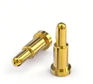
Engineering Summary:
A magnetic pogo pin charging dock can provide a convenient conductive charging interface for wireless gaming controllers, VR motion controllers, gaming mice and other rechargeable peripherals. It is not wireless power transfer and does not independently create fast charging, USB compatibility, battery protection or uninterrupted gameplay. The complete design must coordinate the peripheral geometry, charging contacts, pogo pin working stroke, magnetic capture, mechanical support, power-control circuit, user feedback and product-level validation.
A magnetic pogo pin charging dock can provide a convenient conductive charging interface for wireless gaming controllers, VR motion controllers, gaming mice and other rechargeable peripherals. It is not wireless power transfer and does not independently create fast charging, USB compatibility, battery protection or uninterrupted gameplay. The complete design must coordinate the peripheral geometry, charging contacts, pogo pin working stroke, magnetic capture, mechanical support, power-control circuit, user feedback and product-level validation.
Wireless gaming peripherals remove the data cable from normal gameplay, but they still require an energy source and a charging workflow.Manufacturers may use USB-C cables, replaceable batteries, charging cradles, portable charging cases, magnetic charging stands or contactless charging systems. Each architecture provides a different balance of interoperability, cost, mechanical integration and user convenience.
A magnetic pogo pin dock is most useful when the product requirement is to let the user place the peripheral in a defined location and begin charging without manually inserting a cable into the device.
The interface should be evaluated as a complete dock-and-device system rather than as a group of pogo pins surrounded by magnets.Contact Charging Is Not Wireless Charging
Magnetic pogo pin charging uses conductive contacts. Electrical current passes through the charging-dock circuit, spring-loaded contacts, device-side targets and the peripheral charging circuit.

The peripheral may communicate wirelessly during gameplay, but that does not change the physical charging method.| Charging Architecture | Energy-Transfer Method | Typical User Action |
|---|---|---|
| USB-C cable | Conductive plug-and-receptacle connection | Insert the cable into the peripheral |
| Pogo pin charging dock | Conductive spring-loaded contacts and mating targets | Place or slide the device into the dock |
| Magnetic pogo pin dock | Conductive contacts with magnet-assisted positioning or retention | Approach the dock and allow the mechanical and magnetic structure to locate the device |
| Contactless charging | Electromagnetic energy transfer without direct conductive charging contacts | Place the device within the approved coil-coupling region |
| Replaceable battery | External battery replacement or separate battery charging | Remove and replace the battery or battery pack |
Engineering Note:
Use “magnetic contact charging,” “magnetic charging dock” or “pogo pin charging interface” for a conductive system. Reserve “wireless charging” for an actual contactless energy-transfer architecture.
Use “magnetic contact charging,” “magnetic charging dock” or “pogo pin charging interface” for a conductive system. Reserve “wireless charging” for an actual contactless energy-transfer architecture.
Do Not Position Magnetic Charging as a Universal Replacement for USB-C
USB-C is a standardized and reversible connector system that can support charging, data and accessory interoperability when correctly implemented.

A proprietary magnetic dock can offer a different user experience, but it may require a dedicated accessory and replacement ecosystem.| Requirement | USB-C Interface | Custom Magnetic Pogo Pin Dock |
|---|---|---|
| Accessory interoperability | Can use standardized compatible cables and power sources | Usually requires a dedicated dock, cable or adapter |
| User connection | User inserts a reversible plug | User places the peripheral into a guided dock |
| Data compatibility | Defined by the implemented USB specification | Must be separately designed and validated |
| Enclosure integration | Requires receptacle space and an access opening | Can use custom targets shaped around the product |
| Charging location | Can charge while handheld or placed anywhere within cable reach | Normally requires placement in the matching dock |
| Replacement accessory | Compatible cables are widely available | Replacement availability depends on the product manufacturer |
| Mechanical customization | Limited by standardized connector geometry | Contact layout, dock geometry and targets can be customized |
Some products may benefit from keeping both interfaces: a pogo pin dock for routine charging and a USB-C port for travel, service, firmware recovery or standardized charging.Common Gaming Peripheral Charging Architectures
| Peripheral | Possible Charging Architecture | Primary Engineering Focus |
|---|---|---|
| Wireless game controller | Desktop stand, dual-controller dock or USB-C cable | Grip geometry, center of mass, target position and charging confirmation |
| Controller with replaceable battery pack | Battery-cover adapter with exposed charging targets | Battery-cover fit, controller compatibility and replacement strategy |
| VR motion controller | Charging cradle, battery-door adapter or multi-device dock | Controller orientation, tracking components, straps and magnetic-sensitive sensors |
| VR headset | Headset dock, magnetic cable or combined headset-and-controller station | Headset weight, facial-interface clearance, heat and cable routing |
| Gaming mouse | Magnetic base, charging puck or powered mouse dock | Small targets, desk contamination, easy removal and continued wireless operation |
| Mobile gaming grip | Detachable cable, contact dock or replaceable battery module | Phone compatibility, grip adjustment and cable-load interaction |
| Gaming headset | Vertical stand, charging base or magnetic cable | Headband support, ear-cup orientation and stable dock placement |
| Production or service fixture | Temporary pogo pin programming and test interface | Fixture repeatability, replaceability and electrical test access |
These applications should not be served by one universal connector. A game controller dock and a VR headset stand have different weight, geometry, electrical and user-interaction conditions.Start with the Complete Charging State Sequence
The charging interface passes through several mechanical and electrical states.| State | Mechanical Condition | Recommended Electrical Condition |
|---|---|---|
| Dock empty | No peripheral is installed | Source contacts remain in the defined safe state |
| Peripheral approaching | Controller or accessory enters the capture region | No valid charging connection should be assumed |
| Initial magnetic capture | Magnets begin attracting the device | Presence may be detected, but full seating is not yet confirmed |
| Mechanical location | Guides and support surfaces position the device | The system may evaluate orientation and contact state |
| Fully seated | Mechanical stops establish the intended position | Charging authorization can be evaluated |
| Charging enabled | The peripheral remains supported by the dock | Current is controlled by the charging system |
| Charge completed or maintained | Peripheral remains docked | Battery-management logic controls the final state |
| Removal begins | The user lifts, slides or tilts the device | The charging system detects disconnection and responds as designed |
| Fault state | Foreign object, partial seating or abnormal temperature is detected | Power is limited, disabled or reported according to the product design |
Magnetic attraction alone should not be used as proof that the peripheral is correctly seated and charging.The Dock Must Support the Peripheral Mechanically
The controller, headset or accessory should be supported by the dock housing, cradle, shelf or other defined mechanical surfaces.

The pogo pins and their solder joints should not carry the complete device mass.
A preferred load path is:
Peripheral → dock support surfaces → dock housing → desk or mounting surfacerather than:
Peripheral → magnets → pogo pins → solder joints → charging PCB

The dock design should consider:- Peripheral weight
- Center of mass
- Grip and trigger geometry
- Controller vibration motors or haptic actuators
- User impact when placing the device
- Cable pull on the charging station
- Desk vibration
- Anti-slip feet or weighted base
- One-handed insertion and removal
A weighted base can improve desk stability, but it does not correct poor contact alignment or insufficient mechanical support.Decide Whether Pogo Pins Belong in the Dock or the Peripheral
| Contact Location | Possible Benefit | Primary Trade-Off |
|---|---|---|
| Pogo pins in the charging dock | Moving contacts remain in the replaceable accessory | The dock must accurately control working stroke and target position |
| Pogo pins in the controller | The dock can use flat targets | Moving contacts occupy device space and remain exposed during normal use |
| Flat targets in a replacement battery cover | Can add dock charging without redesigning the entire controller housing | Battery-cover fit, compatibility and internal battery connection become critical |
| Dedicated target inserts in the peripheral | Target finish and mechanical attachment can be controlled | Adds parts, assembly steps and internal terminations |
| PCB pads used as direct targets | May reduce component count | Board support, finish, flatness, wear and repairability must be reviewed |
For many consumer charging docks, putting the pogo pins in the replaceable dock and flat targets on the peripheral can simplify repair and reduce the number of moving components exposed on the gaming device.Control the Pogo Pin Working Stroke
Working stroke is the compression applied to each pogo pin after the peripheral reaches its final docked position.The tolerance stack may include:
- Pogo pin free-height tolerance
- Pin mounting height
- Dock PCB position
- Dock housing dimensions
- Controller or peripheral housing dimensions
- Target-contact position and flatness
- Mechanical-stop tolerance
- Battery-cover fit
- Dock-support deformation
- Debris trapped beneath the device
| Condition | Possible Result |
|---|---|
| Compression below the approved minimum | Intermittent charging, false detection or increased voltage drop |
| Compression within the approved range | Intended contact force and electrical behavior |
| Compression above the approved maximum | Spring bottoming, excessive reaction force or PCB loading |
| Unequal compression | Different contact forces and uneven current sharing |
The final seated distance should be established by the dock’s mechanical stops. Magnets should not force the contacts into uncontrolled maximum travel.Magnetic Capture Is Not the Same as Mechanical Alignment
Magnets can assist the final approach and provide retention, but the product still needs defined locating features.Possible features include:
- Controller-shaped cradle surfaces
- Grip supports
- Asymmetric housing geometry
- Locating ribs or recesses
- Battery-cover features
- Target-contact spacing
- Dedicated orientation guides
- Mechanical stops
Increasing magnet grade or magnetic field strength does not automatically improve docking.Excessive attraction may:
- Increase seating impact
- Increase removal effort
- Load the housing or battery cover
- Increase pogo pin compression
- Attract metallic desk debris
- Interact with magnetically sensitive components
Review Magnets Around Hall-Effect Joysticks and Triggers
Some gaming controllers use Hall-effect or other magnetic sensing technologies for joysticks, triggers, position detection or accessory sensing.

An external permanent magnet located near a magnetic sensor may alter the field experienced by that sensor. Whether this creates an error depends on:- Sensor type
- Sensor orientation
- Magnet location
- Magnet dimensions and magnetization direction
- Distance between the charger and sensor
- Magnetic return structure
- Controller housing materials
- Software calibration and compensation
The charging magnet arrangement should be evaluated with the complete powered controller.Recommended checks include:
- Joystick center position before, during and after docking
- Full joystick movement range
- Trigger output range
- Calibration retention
- Controller wake and sleep behavior
- Magnetic-sensor diagnostics where available
- Performance with the strongest and weakest production magnets
Engineering Note:
A closed magnetic circuit or alternating-pole layout may reduce external field in some designs, but it cannot be described as supporting zero interference with Hall-effect controls without complete controller testing.
A closed magnetic circuit or alternating-pole layout may reduce external field in some designs, but it cannot be described as supporting zero interference with Hall-effect controls without complete controller testing.
Treat Partial Docking as a Real Electrical State
| Partial-Docking Condition | Possible Risk | Required Review |
|---|---|---|
| One controller grip reaches the stand first | The contact sequence differs from the nominal position | Approach geometry and support-surface sequence |
| One pogo pin touches first | Power or detection is present without the intended return | Pin-height and target-position tolerances |
| Controller is tilted | Unequal contact compression | Cradle support points and center of mass |
| Controller is magnetically retained but unseated | False charging indication | Independent charging-state verification |
| Incorrect battery cover is installed | Targets are absent, offset or electrically incompatible | Accessory compatibility and identification |
| Foreign object bridges the contacts | Short circuit, heating or source shutdown | Current limiting and power authorization |
| Controller is removed during charging | Electrical interruption or transient behavior | Charging-system response and reconnection |
Mechanical coding, contact spacing, device detection and controlled power enable may be combined to reduce risk.Fast Charging Is Not a Pogo Pin Feature by Itself
Charging time depends on the complete system, including:- Power-source capability
- Dock input circuit
- Charging-controller design
- Battery chemistry and capacity
- Battery temperature
- Controller charging profile
- Connector voltage drop
- Thermal limits
- Firmware charging strategy
The pogo pin interface should be specified by its electrical and thermal conditions rather than by a general “fast charging” label.Define:
- Operating voltage
- Maximum continuous current
- Peak current and duration
- Permitted voltage drop
- Permitted connector temperature rise
- Ambient temperature
- Number of parallel power and return contacts
- Contact state during insertion and removal
- Fault-current limit
Parallel Contacts May Not Share Current Equally
Multiple pogo pins may be connected in parallel, but current distribution can vary because of:- Different compression levels
- Contact-resistance variation
- Target flatness
- PCB copper routing
- Battery-cover tolerances
- Contamination
- Different termination paths
Channel-level voltage drop and temperature should be measured where several contacts share the charging current.Develop the Pin Map from Actual Functions
| Possible Contact Function | Engineering Question |
|---|---|
| Charging power | What voltage and current are required? |
| Power return | What return path exists during every credible docking state? |
| Dock detection | Does it identify initial presence or verified full seating? |
| Controller identification | Must the dock distinguish controller type, battery pack or accessory? |
| Charging authorization | What condition enables source power? |
| Temperature monitoring | Is temperature measured in the battery, controller, dock or charging circuit? |
| Service data | Is wired diagnostics or programming required while docked? |
| Lighting control | Is RGB or status communication local to the dock or exchanged with the peripheral? |
Many charging docks only need power, return and possibly a detection or identification function.

Adding four, five or more contacts does not automatically create USB data, battery telemetry or profile synchronization.
Multi-Pin Contacts Do Not Automatically Support USB
USB compatibility depends on the complete physical and protocol implementation.Review:
- Implemented USB version
- Differential-pair geometry
- Characteristic impedance
- Signal-return environment
- Connector discontinuity
- PCB routing
- Cable construction
- ESD protection
- Complete channel length
- Protocol and compliance testing
A dock intended only for charging should not be described as supporting firmware updates, macro synchronization or USB 2.0 merely because it contains four or five contacts.

Where standardized USB data is required, keeping a USB-C port or using a qualified USB connector may be more appropriate.
Design Dual-Controller and Multi-Device Stations as Power Systems
A dual charging station is not simply two single docks placed in the same housing.Review:
- Total input-power budget
- Current available to each charging position
- Independent or shared charging controllers
- Fault isolation between positions
- Thermal interaction
- Simultaneous insertion and removal
- Controller compatibility
- Individual charge indication
- Behavior when one device is fully charged
- Behavior when one position is shorted or contaminated
| Multi-Dock Function | Required Definition |
|---|---|
| Independent charging status | Each position should report its own charging, complete or fault state |
| Power sharing | Define whether current is fixed, shared or dynamically allocated |
| Fault isolation | A fault at one position should produce the intended system response |
| Thermal control | Measure both positions under simultaneous maximum charging |
| Accessory identification | Define response to unsupported controllers or battery covers |
RGB lighting and status synchronization are separate electronic and software functions. They are not created by the pogo pin connector.Exposed Dock Contacts Require a Safe Electrical State
When the controller is removed, charging-dock contacts may be accessible on a desk.Foreseeable contact may include:
- Coins
- Keys
- Headphone plugs
- USB connector shells
- Metal desk accessories
- Drink residue
- Cleaning cloths
- Children’s objects
- Incorrect peripherals
Possible controls include:
- Current limiting
- Normally de-energized source contacts
- Peripheral detection before charging
- Recessed contact positions
- Insulating barriers
- Timed authorization
- Short-circuit shutdown
- Fault indication
Permanent magnets may attract conductive ferrous particles toward the charging area, so foreign-object evaluation should include the magnetic structure.Quick Disconnect Can Help—or Create Another Failure Mode
A magnetic cable may release before a strong cable pull moves the controller, headset or console accessory.

However, quick release is not automatically safer or more reliable.
Define:
- Normal cable direction
- Intended retention force
- Release direction
- Peripheral mass
- Desk friction
- Expected user movement
- Electrical state during separation
- Whether unintended disconnection interrupts gameplay or charging
An “under 0.1-second disconnect” claim has little engineering value without defining the applied load, movement direction, sampling method and required response.Mechanical Endurance Is Not Friction-Free
Pogo pins contain moving mechanical parts. The plunger moves inside the barrel, the spring compresses, and the tip contacts the target surface.

Depending on the approach direction and housing geometry, the contact may experience:- Axial compression
- Sliding
- Wiping
- Side load
- Impact
- Contamination abrasion
Therefore, pogo pin charging should not be described as having “zero mechanical friction.”Cycle-life evaluation should identify:
- Tested connector and target
- Working stroke
- Electrical load
- Mating direction
- Cycle rate
- Environmental condition
- Cleaning interval
- Acceptance criteria
- Post-test resistance and visual inspection
A cycle result cannot be converted directly into a number of calendar years without a documented user-frequency model.Gaming Peripherals Create Specific Contamination Conditions
| Exposure | Possible Effect | Design Input |
|---|---|---|
| Hand oils and perspiration | Surface films and changing contact behavior | Target location and cleaning method |
| Dust and fabric fibres | Blocked pogo pin movement or incomplete seating | Desk environment and cradle geometry |
| Food or drink residue | Conductive contamination, corrosion or sticky movement | Cleaning access and source-contact protection |
| Metal fragments | Accumulation near magnets or contact bridging | Magnet position, spacing and recess design |
| Cleaning chemicals | Housing discoloration, coating damage or residue | Approved cleaning agent and application method |
| Pet hair | Uneven seating and trapped contamination | Cradle opening and inspection access |
Contact targets and dock pogo pins should remain visible or accessible enough for inspection and cleaning.Ingress Protection Belongs to the Complete Enclosure
Flush charging targets may make the peripheral enclosure easier to design than a deep receptacle in some products.

However, removing a USB receptacle does not automatically create a waterproof or dustproof device.
The enclosure boundary may include:
- Target-contact inserts
- Adhesive or potting
- Housing joints
- Buttons and triggers
- Speaker and microphone openings
- Battery doors
- Joystick openings
- Charging-contact terminations
Any IP classification should identify the tested complete assembly, device condition and test method.When May a Magnetic Pogo Pin Charging Dock Be Appropriate?
| Project Requirement | Possible Value |
|---|---|
| Routine desktop charging | The player can place the peripheral in a defined charging location |
| One-handed docking | Mechanical guidance and magnetic capture may simplify final positioning |
| Custom controller geometry | Targets and dock supports can be developed around the housing |
| Dual-controller charging | Several independent charging positions can be integrated into one stand |
| Replaceable battery-cover adapter | Charging targets can be integrated into a dedicated battery cover |
| Accessible service part | Dock-side pogo pins may be easier to replace than an internal controller port |
| Separate routine charging from data | The dock can handle charging while USB or wireless communication remains separate |
When May USB-C or Another Architecture Be More Appropriate?
Another charging interface may be preferable when the product requires:
- Use of widely available standard cables
- Charging during travel without a dedicated dock
- Standardized USB data and power negotiation
- A positive mechanical connection during gameplay
- No permanent magnets near magnetic sensors
- No exposed conductive contacts
- Very low accessory-development cost
- Compatibility with an existing charging ecosystem
- Contactless charging as a core product feature
A hybrid product may retain USB-C while also offering a proprietary charging dock.Recommended Validation Plan
| Requirement | Possible Evaluation |
|---|---|
| Peripheral packaging | Controller, battery, PCB, targets, magnets and housing dimensional review |
| Dock mechanical support | Center of mass, grip support, base stability and one-handed use |
| Working stroke | Minimum, nominal and maximum pogo pin compression |
| Magnetic capture | Approach, retention, seating impact and removal direction |
| Partial docking | Tilted, offset, one-contact-first and captured-but-unseated states |
| Hall-sensor interaction | Joystick and trigger outputs before, during and after docking |
| Electrical path | Contact resistance, voltage drop and temperature rise |
| Charging control | Inrush, current limiting, timeout, overtemperature and removal during charging |
| Parallel contacts | Current distribution and individual contact temperature |
| Dual-device charging | Both positions operating at the maximum intended load |
| Fault isolation | Short circuit or incompatible peripheral in one charging position |
| Foreign objects | Representative conductive objects and ferrous debris |
| Repeated docking | Project-defined cycles with electrical and visual inspection |
| Contamination | Hand oil, dust, drink residue and cleaning conditions |
| USB or data channel | Complete physical and protocol validation where implemented |
| User feedback | Charging, complete, fault and unsupported-device indications |
| Battery safety | Complete cell, charging circuit and foreseeable misuse evaluation |
| Product safety | Finished dock and gaming peripheral under applicable requirements |
Information Required for an Engineering Review
| Requirement Group | Information to Provide |
|---|---|
| Peripheral type | Controller, VR accessory, mouse, headset or mobile gaming device |
| Charging architecture | Desktop stand, dual dock, charging case, magnetic cable or battery-cover adapter |
| Device geometry | 3D model, center of mass, support surfaces and restricted regions |
| Contact area | Available length, width, curvature, position and target material |
| Pin Map | Power, return, detection, identification, service and data functions |
| Electrical conditions | Voltage, continuous current, peak current and charging profile |
| Charging control | Power enable, current limiting, timeout and fault response |
| Dock geometry | Approach direction, supports, stops, base and removal movement |
| Magnetic behavior | Capture, retention, seating impact and intended release force |
| Magnetic-sensitive components | Hall-effect sticks, triggers, sensors, speakers and restricted magnet regions |
| Multi-device operation | Number of charging positions, total input power and simultaneous use |
| Environment | Dust, hand oils, drink exposure, metallic debris and cleaning process |
| Communication | Charge-only, USB, service data or another physical channel |
| Files | 2D drawings, 3D models, PCB layout, schematic and charging-dock design |
| Commercial | Prototype quantity, production forecast and development stage |
Common Engineering Mistakes
| Mistake | Possible Consequence | Better Approach |
|---|---|---|
| Calling pogo pin charging wireless charging | The product architecture is described incorrectly | Use magnetic contact charging or conductive dock charging |
| Claiming USB-C is obsolete or unreliable | The article ignores standardization and interoperability | Compare the two architectures objectively |
| Calling magnetic pogo pins the industry standard | The claim is not supported across all gaming platforms | Present them as one available custom charging architecture |
| Using magnets as the only locating feature | Partial seating and uneven contact compression | Use cradle geometry, guides and mechanical stops |
| Maximizing magnetic force | High impact, difficult removal and sensor interaction | Balance capture, retention and user handling |
| Claiming zero Hall-sensor interference | Stray magnetic fields are not evaluated | Test the complete powered controller |
| Calling the contact system fast charging | Battery and charging-circuit responsibilities are ignored | Define current, voltage drop and temperature rise |
| Assigning USB data by pin count | The physical channel may not meet the protocol requirements | Validate the complete USB implementation |
| Claiming zero mechanical friction | Plunger motion, wiping and target wear are ignored | Validate the actual mating movement and cycle conditions |
| Using pogo pins to support controller weight | Contact, PCB or solder-joint damage | Provide a separate mechanical load path |
| Leaving exposed contacts uncontrolled | Foreign-object short circuits or heating | Use detection, current limiting and power authorization |
| Publishing a universal cycle-life value | The claim does not match the finished dock | State the tested parts, stroke, load and acceptance criteria |
Engineering Reference Sources
Applicable editions, regional requirements and acceptance criteria should be confirmed for the finished gaming peripheral and charging accessory.-
USB-IF — USB Type-C cable and connector specification
-
PlayStation — DualSense controller and click-in charging-station architecture
-
Razer — Xbox controller charging stand with magnetic contact system
-
Nintendo — Slide-in and USB-C-dongle controller charging dock
-
Allegro MicroSystems — Effects of permanent magnets and stray fields on Hall-effect sensors
-
IEC 60512-2-2 — Contact resistance measurement
-
IEC 60512-9-1 — Mechanical operation endurance without electrical load
-
IEC 60512-9-3 — Mechanical operation with electrical load
-
IEC 62368-1:2023 — Safety requirements for audio, video and information technology equipment
-
IEC 62133-2 — Portable sealed lithium-cell and battery safety
Frequently Asked Questions
Is a magnetic pogo pin charging dock wireless charging?
No. Electrical current passes through conductive pogo pins and mating targets. The peripheral may be wireless during gameplay, but the charging interface is contact-based.Can a magnetic charging dock replace USB-C?
It may replace routine cable insertion in a proprietary product, but it does not automatically provide USB interoperability, data transfer or standardized accessory compatibility.Are pogo pin charging docks suitable for every controller?
No. Suitability depends on controller geometry, battery architecture, available target area, charging requirements and magnetic-sensitive components.Does magnetic attraction supports correct charging?
No. A controller may be magnetically captured without reaching the required pogo pin compression. Mechanical seating and charging confirmation are still required.Can charging magnets affect Hall-effect joysticks?
External magnetic fields may affect magnetic sensors depending on their position, orientation and design. The complete powered controller should be evaluated with the production magnet arrangement.Can pogo pins support fast charging?
They may carry a project-defined charging current when the complete contact path, voltage drop and temperature rise have been validated. Actual charging speed depends on the power source, battery and charging electronics.Can a four-pin or five-pin dock support USB data?
Pin count alone does not prove USB compatibility. The complete differential channel, PCB routing, protection circuit and protocol implementation must meet the applicable requirements.Do pogo pins have zero mechanical friction?
No. The plunger moves inside the barrel, the spring compresses and the contact tip engages the target. Sliding or wiping may also occur depending on the dock geometry.Should magnets hold the full weight of the controller?
Normally the dock housing and support surfaces should carry the controller weight. Magnets may assist capture or retention rather than replace the structural support.What information is needed for a custom gaming charging dock review?
Provide the peripheral model, 3D geometry, center of mass, contact area, Pin Map, electrical conditions, charging circuit, magnetic-sensitive components and dock concept.Prepare Your Gaming Peripheral Charging Project
Review current

    custom magnetic connector components

when the project requires a connector pair for integration into the controller and charging dock.

Compare

    pogo pin connector assemblies

when magnetic capture is not required.

When the project requires a finished charging lead, cable, strain relief and opposite-end termination, review

    custom magnetic cable assemblies
.

Additional design resources are available through the

    CTP connector engineering guides
.

Submit the peripheral drawings, charging-dock concept, Pin Map, electrical conditions and magnet restrictions through the

    Get Quote & Samples page
.


    CTP can review the connector supply scope, pogo pin layout, working stroke, mating targets, magnetic arrangement, PCB or cable termination and dock interface. Final charging speed, battery safety, USB compatibility, Hall-sensor performance, product safety and finished-device compliance must be confirmed for the complete customer product.