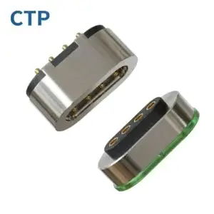
Magnetic pogo pins can be useful in demanding applications when the
interface requires removable contact, blind docking, spring compliance or
magnet-assisted capture. However, magnetic retention alone does not prove
vibration stability, high-current capability, waterproof performance or
long service life. A robust design should begin with the product mission
profile and validate four connected stress domains: mechanical disturbance,
electrical and thermal loading, environmental exposure, and abnormal
mating states.
A Demanding Application Is a Stress Profile, Not an Industry Label
Engineers often describe a connector as suitable for “automotive,”
“industrial,” “medical” or “outdoor” use.

Those labels are useful for context, but they do not define the actual
stresses experienced by the interface.

Two products in the same industry can place completely different demands
on a connector.
One interface may experience:
- frequent docking but little vibration;
- continuous vibration but very few mating cycles;
- high current only while fully seated;
- water exposure only while unmated;
- dust combined with magnetic metallic debris;
- repeated cleaning but low electrical load.
For this reason, the first engineering task should be to create a
mission profile.
A useful connector mission profile can define:
| Stress Area | Questions to Define |
|---|---|
| Mechanical | Vibration, shock, cable load, mating angle and docking tolerance |
| Electrical | Voltage, continuous current, peak current, duty cycle and signals |
| Thermal | Ambient temperature, internal heating and allowable temperature rise |
| Environmental | Water, humidity, dust, sweat, salt, oil, chemicals or debris |
| Mating | Fully seated, partial, tilted, contaminated and unmated states |
| Lifecycle | Mating frequency, maintenance and expected service life |
Once this stress envelope is defined, engineers can decide whether a
magnetic pogo pin architecture is appropriate and what must be validated.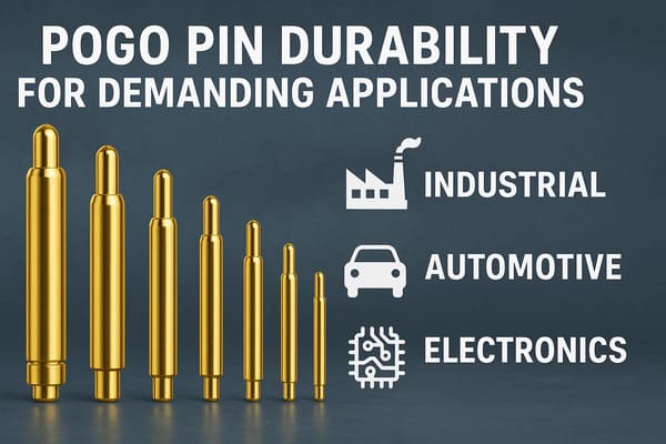
electrical and environmental stress conditions rather than by an
industry label alone.
Stress Domain 1: Mechanical Disturbance and Connection Stability
A magnetic pogo pin interface contains several different mechanical
functions that should not be combined into one “magnetic force” value.
A useful function split is:
    Product Approach
    →
    Mechanical Guidance
    →
    Magnetic Capture
    →
    Final Seating
    →
    Pogo Pin Compression
    →
    Electrical Contact


Magnets can assist capture and provide seated retention.

They should not automatically be expected to establish precision X-Y-Z
location or compensate for uncontrolled product-level motion.
Separate Gross Motion from Contact Compliance
Pogo pin working stroke is primarily useful for controlled movement along
the spring axis.

It can accommodate some Z-axis tolerance, but it does not replace:- mechanical guides;
- housing datums;
- hard stops;
- robot docking accuracy;
- structural restraint.
A robust interface normally lets different features solve different
mechanical problems.| Mechanical Function | Typical Design Element |
|---|---|
| Coarse Positioning | Product or docking structure |
| X-Y Alignment | Mechanical guides and datums |
| Final Z Position | Mechanical stop |
| Capture | Magnetic system where required |
| Electrical Compliance | Pogo pin working stroke |
Working Stroke Must Be Evaluated Under the Real Tolerance Stack
A simplified relationship is:
S = Hfree - Hseatedwhere:
- S = actual pogo pin compression;
- Hfree = installed free height;
- Hseated = installed height after final seating.
The real value can vary because of:- pogo pin free-height tolerance;
- PCB thickness;
- solder height;
- housing tolerance;
- target-pad position;
- module flatness;
- mechanical-stop variation.
Mechanical qualification should therefore include minimum, nominal and
maximum compression conditions.
Vibration Stability Must Be Measured Electrically
A connector remaining physically attached during vibration does not prove
that every electrical path remained continuous.

For applications sensitive to intermittent contact, define:- the vibration or shock condition;
- monitoring bandwidth;
- allowed interruption duration;
- electrical load;
- acceptance criteria.
This is more meaningful than assuming that magnetic attraction automatically
eliminates contact interruption.
Capture Force and Retention Force Are Different Questions
Magnetic behavior can be divided into:- capture behavior during approach;
- seated retention;
- axial separation;
- peel separation;
- off-axis response.
A magnet system that performs well in one direction may behave differently
under peel or cable-induced torque.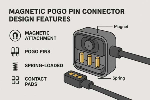
compliance should be treated as separate interface functions.
Stress Domain 2: Electrical and Thermal Loading
A demanding power application should not be designed from one current
number printed in a connector catalog.

The pogo pin is only one part of the complete conductive path.
A practical path may look like:
    Power Source
    →
    PCB / Cable
    →
    Termination
    →
    Pogo Pin
    →
    Mating Interface
    →
    Target
    →
    Device PCB
    →
    Load
A simplified total resistance can be expressed as:
    Rpath =
    Rsource +
    Rtermination +
    Rpogo +
    Rinterface +
    Rtarget +
    Rdevice
Voltage drop is:
Vdrop = I × Rpathand resistive loss is:
Ploss = I² × RpathHigh Current Is Primarily a Thermal Validation Problem
As current rises, relatively small changes in resistance can create a
significant change in heat generation because resistive loss increases with
the square of current.

Current validation should therefore consider:- complete-path voltage drop;
- temperature rise;
- ambient temperature;
- working stroke;
- mating-target condition;
- termination resistance;
- duty cycle;
- post-aging resistance.
Temperature Should Be Measured Where the Hotspot Actually Develops
The hottest point is not necessarily the location that is easiest to reach
with a sensor.

Potential thermal contributors include:- pogo contact interfaces;
- PCB copper;
- wire termination;
- parallel contact imbalance;
- local enclosure insulation.
Sensor placement should therefore follow the expected thermal path.Parallel Contacts Do Not Automatically Share Current Equally
Several pogo pins can be placed in parallel for power or return, but
individual branch currents may differ.
Current sharing can be affected by:
- working-stroke variation;
- contact-resistance variation;
- target flatness;
- module tilt;
- PCB routing;
- termination resistance.
A multi-contact power interface should therefore be evaluated as an array
rather than as several closely identical resistors.
Dynamic Electrical States Matter
The electrical risk can be very different between:- fully seated operation;
- connection under load;
- separation under load;
- partial mating;
- intermittent contact during disturbance.
If the application does not require mating or separation while energized,
the system can be designed to remove or reduce power before those events.
Data Capability Is Not Determined by Pin Count
For signal-sensitive applications, channel performance can depend on:- signal and return allocation;
- contact pitch;
- contact geometry;
- PCB transitions;
- reference-plane continuity;
- cable or FPC structure;
- crosstalk;
- complete channel length.
Therefore:

More contacts do not automatically mean more bandwidth.
Stress Domain 3: Environment, Contamination and Aging
Demanding environmental performance should not be reduced to a single
“waterproof” or “corrosion-resistant” label.

Different exposures create different failure mechanisms.| Environmental Stress | Possible Interface Effect |
|---|---|
| Water / Condensation | Wet contacts, leakage paths or residue after drying |
| Salt / Sweat | Corrosion and conductive residue |
| Dust | Incomplete seating or abrasive wear |
| Metallic Debris | Magnetic accumulation near the mating interface |
| Oil / Chemicals | Material compatibility or contact-film effects |
| Temperature Cycling | Dimensional change, seal stress and contact-position variation |
Environmental Protection Has a Boundary
If ingress protection is required, engineers should identify the complete
environmental boundary.
It can include:
- pogo pin feedthroughs;
- connector housing;
- housing-to-device joints;
- gaskets;
- potting;
- target installation;
- PCB, FPC, wire or cable terminations.
A flat contact surface or a visible seal does not by itself establish a
specific ingress-protection rating.
Mated and Unmated Environmental States May Be Completely Different
A removable magnetic connector may spend much of its service life unmated.

The device-side contacts can then be exposed even if the electronics behind
the connector remain sealed.
The design should therefore consider:
- fully mated condition;
- partially mated condition;
- unmated condition;
- wet reconnection;
- post-cleaning condition.
Magnets Introduce a Unique Debris Mechanism
Ferromagnetic particles can be attracted toward the connector surface.Accumulated debris may:
- prevent complete seating;
- change pogo pin working stroke;
- scratch target surfaces;
- bridge conductive regions;
- retain moisture.
This failure mechanism should be considered wherever metallic contamination
is realistic.
Environmental Testing Should Include Post-Exposure Measurements
A connector may survive an environmental exposure without visible damage
while its electrical performance has still changed.
Depending on the project, post-test checks can include:
- contact resistance;
- voltage drop;
- temperature rise;
- working stroke;
- contact force;
- surface condition;
- magnetic retention;
- housing and seal condition.
Stress Domain 4: Partial Mating and Abnormal Connection States
This is one of the most important engineering areas in a demanding magnetic
pogo pin application—and one of the easiest to overlook.

Magnetic attraction can begin before the connector reaches its final
mechanically seated position.

That means the connector may temporarily enter states such as:- one edge attached first;
- only some pogo pins compressed;
- power contacts engaged before signal contacts;
- a foreign object blocking final seating;
- contacts touching while the connector is tilted;
- a cable being pulled away while current is flowing.
These states can matter more than the nominal fully seated condition.Magnetic Attachment Is Not Proof of Valid Electrical Mating
A useful system can distinguish:


    Magnetic Capture
    ≠
    Mechanical Seating
    ≠
    Valid Electrical Connection


Depending on application risk, the system may require a separate method to
determine whether the connector is actually ready for full electrical
operation.
Connection Sequencing Can Reduce Fault Exposure
A system-level architecture might use:


    Connector Approaches
    →
    Magnetic Capture
    →
    Mechanical Seating
    →
    Connection Detection
    →
    Required Signals Validated
    →
    Main Power Enabled


The exact sequence depends on the product.

The important principle is that magnetic attraction and power enable do not
have to occur at the same time.
A Longer Contact Can Provide State Information—but Not Safety by Itself
A pilot or make-first contact can help identify connector state.

However, that contact alone does not eliminate electrical arcing or protect
the system.

The controller must use the information to perform the required electrical
action.
Test Fault States Deliberately
Prototype validation should not include only the perfect mating event.Useful fault-oriented tests can include:
- X-Y offset;
- angular offset;
- partial compression;
- slow separation;
- rapid separation;
- debris-blocked mating;
- wet contact state;
- wrong module or accessory where applicable.
Demanding Applications Usually Combine Multiple Stress Domains
Real field failures often occur because several stresses interact.

For example:


    Vibration
    +
    Minimum Working Stroke
    +
    Contact Contamination
    +
    Electrical Load
    →
    Higher Intermittency Risk
or:
    High Ambient Temperature
    +
    Contact Resistance Drift
    +
    High Current
    →
    Higher Interface Temperature
or:
    Metallic Debris
    +
    Magnetic Attraction
    +
    Partial Seating
    →
    Invalid Electrical Connection


This is why testing each parameter separately may not be enough for a
high-risk application.
Build a Combined-Stress Validation Matrix
| Stress Combination | What to Evaluate |
|---|---|
| Vibration + Electrical Load | Intermittency, voltage drop and temperature |
| Temperature + High Current | Thermal margin under worst-case ambient |
| Contamination + Mating Cycles | Seating, resistance and wear trend |
| Moisture + Powered Contacts | Wet-state electrical behavior |
| Offset + Minimum Stroke | Contact stability across tolerance extremes |
| Debris + Magnetic Capture | False seating and conductive bridging |
| Aging + Current | Post-life voltage drop and temperature rise |
Define Failure Before Starting Validation
A demanding application cannot be validated simply by stating:

“The connector still works.”

Engineers should define measurable acceptance limits.| Performance Area | Possible Acceptance Metric |
|---|---|
| Electrical Continuity | Maximum allowed interruption |
| Contact Resistance | Project-defined limit or drift |
| Voltage Drop | System-level maximum |
| Temperature Rise | Validated thermal limit |
| Working Stroke | Approved operating window |
| Retention | Defined normal-use range |
| Seating | Complete engagement under allowed tolerance |
| Environmental | Project-defined post-exposure performance |
A Better Validation Sequence for Demanding Applications
Instead of starting with a catalog specification, use the following
workflow:


    Define Mission Profile
    →
    Identify Stress Domains
    →
    Define Failure Modes
    →
    Set Acceptance Criteria
    →
    Build Prototype
    →
    Test Individual Stresses
    →
    Test Critical Stress Combinations
    →
    Inspect Degradation
    →
    Freeze Design
    →
    Validate Production Samples
When Magnetic Pogo Pins May Not Be the Best Architecture
Demanding conditions do not automatically mean a magnetic pogo pin
connector is the correct solution.
A different architecture may be more appropriate when:
- the connection must remain positively locked for long periods;
- universal third-party interoperability is required;
- very high contact density is the primary requirement;
- a standardized high-speed connector already meets the system need;
- the connection is permanent and rarely serviced;
- metallic contamination makes magnetic capture difficult to manage.
The value of magnetic pogo pins is strongest when the project benefits from
a removable spring-contact interface, not simply because the operating
environment is difficult.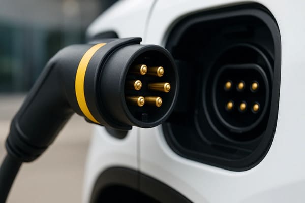
temperature and contamination. Actual suitability requires
project-specific system validation.
Engineering Inputs Required for a Demanding-Application Review
| Project Input | Information to Provide |
|---|---|
| Application | What are the two assemblies being connected? |
| Mating Profile | Manual, automatic, frequency and approach direction |
| Mechanical Envelope | Available X, Y and Z space |
| Tolerance | X-Y-Z and angular variation |
| Working Stroke | Minimum, nominal and maximum pogo compression |
| Pin Map | Power, return, detection and signal functions |
| Electrical Load | Voltage, continuous current, peak current and duty cycle |
| Signal Requirement | Required communication or control channel |
| Mechanical Disturbance | Vibration, shock, cable force or module acceleration |
| Magnetic Behavior | Capture, retention and separation expectations |
| Environment | Temperature, moisture, salt, sweat, dust, oil or chemicals |
| Lifecycle | Expected service life and mating profile |
| Failure Criteria | Electrical, thermal and mechanical acceptance limits |
Frequently Asked Questions
Are magnetic pogo pins suitable for demanding applications?
They can be a strong option when the application benefits from removable
spring contacts, blind docking, magnetic capture or compact interface
geometry. Suitability still depends on project-specific mechanical,
electrical, environmental and lifecycle validation.
Do magnets prevent pogo pin contact interruption during vibration?
Magnetic retention can help maintain the connector assembly, but it does
not by itself prove uninterrupted electrical contact. Dynamic continuity
should be measured under the actual mechanical test condition.
Do stronger magnets make a pogo pin connector more reliable?
Not automatically. Stronger attraction can increase retention but may also
increase impact, removal effort, lateral sliding and metallic-debris
attraction. Magnet design should follow the required capture and separation
behavior.
Can magnetic pogo pins carry high current?
They can be designed as part of higher-current interfaces, but the actual
capability depends on the complete conductive path, working stroke, mating
target, termination, temperature rise and duty cycle.
Can several pogo pins be connected in parallel for higher current?
Yes, but current sharing may not be equal. Contact resistance, stroke,
target flatness, PCB routing and module tilt should be included in the
validation.
Are magnetic pogo pins automatically suitable for high-speed data?
No. Pin count does not determine bandwidth. Signal-return allocation,
contact geometry, PCB transitions, cable or FPC structure and the complete
channel must be evaluated.
Are magnetic pogo pin connectors automatically waterproof?
No. Ingress protection depends on the complete connector and enclosure
boundary, including feedthroughs, housing joints, seals and terminations.
What is partial mating in a magnetic pogo pin connector?
Partial mating occurs when magnetic attachment or some contact engagement
happens before the connector reaches its final seated position. It should
be treated as a separate electrical and mechanical state.
Why is metallic debris important for magnetic connectors?
Ferromagnetic particles can be attracted toward the interface and may
interfere with seating, working stroke, contact surfaces or electrical
spacing.
Should vibration and electrical load be tested together?
When both stresses occur simultaneously in the real application, combined
testing can reveal intermittent or thermal behavior that separate tests may
not show.
How should magnetic pogo pins be validated for a harsh application?
Start with the mission profile, identify mechanical, electrical,
environmental and mating-state stresses, define measurable failure criteria,
test important stress combinations and confirm performance after aging.
When should I avoid magnetic pogo pins?
Another connector architecture may be more appropriate when positive
locking, standardized interoperability, very high contact density,
permanent mating or unmanaged metallic contamination is the dominant
requirement.
Request a Demanding-Application Connector Engineering Review
Explore

    CTP custom magnetic connector solutions

for removable charging, docking and modular hardware interfaces.

Review

    pogo pin and spring-contact connector solutions

for project-specific contact layouts and mounting structures.

Learn more about CTP engineering and manufacturing capabilities on the

    About Us page
. Submit your connector envelope, Pin Map, working stroke, voltage,
current, mating tolerance, magnetic behavior, environmental exposure
and expected service profile to CTP for an engineering review.
The interface can be reviewed against the combined mechanical,
electrical and environmental stress conditions before the connector
geometry is frozen.
Final current capability, signal performance, environmental protection,
vibration stability and lifecycle should be confirmed against the
approved connector revision and project-specific validation conditions.